
Abstract
The problem of elastic indentation by a punch having the form of a flat front face but with edge rounding, and subject to both a normal load and moment, indenting an elastically similar half-plane is considered. Contact pressure in the neighbourhood of the edges shows a local peak, and the object of the paper is to show how different combinations of normal load and moment can give rise to the same near edge behaviour and peak pressure. The result found is very simple, and of direct practical application in fretting fatigue studies, both analytical and experimental.
Introduction
The most common form of stationary contact we encounter in studies of fretting fatigue is one where the basic geometry of the contact-defining body has the form of a flat face with small radii at the ends. This is the basic shape of the dovetail root of a gas turbine fan blade and also the locking segments found in riser-wellhead connectors. Therefore, in order to obtain the best match of the behaviour of a contact under experimental conditions, that is also the form of the pad we use in laboratory fretting fatigue tests. There are four quantities which are important in defining the contact edge state of stress, including the effects of slip or localised plasticity: these are the normal load,
Contacts having the ‘flat and rounded’ form, Figure 1, may not be particularly well modelled using half-plane theory if the contact extends a significant distance around the corner radius, so that the contact half-width,
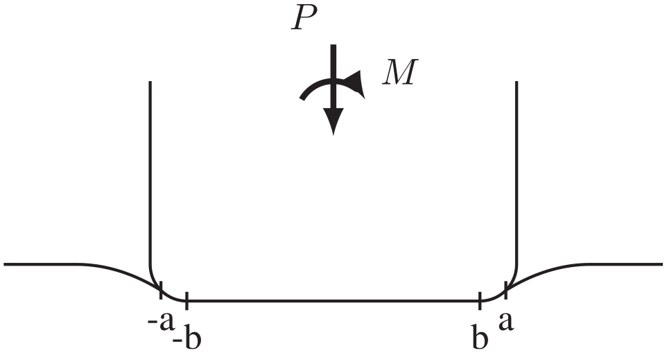
The geometry of a flat and rounded punch, as commonly used in fretting fatigue experiments.
Domain shape of the contact edge
Before we develop the theory itself it will be helpful to look in some detail at the nature of the contact edge and its characteristic form, and in this sense this is a development of the argument made at the beginning of the last paragraph. The geometry under consideration is shown in Figure 2, which shows a close up of the edge of the contact in Figure 1. For simplicity we will assume that the bodies forming the contact have the same elastic properties, with Young’s modulus
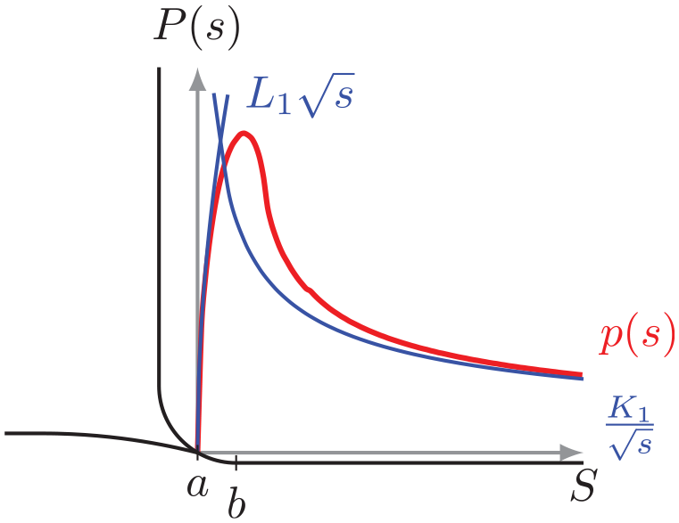
The geometry of the corner of the flat and rounded punch, showing the stress asymptotes.
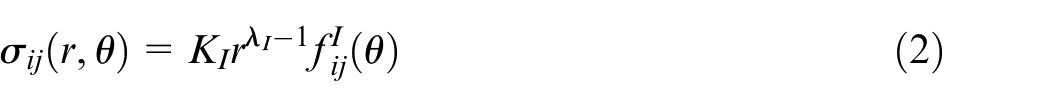
If, first, we zoom very close in to the extreme edge of the contact, each body clearly behaves like a half-plane, and therefore, if we take a coordinate

where
What we would like to do is to establish an asymptotic form which extends further out from the contact edge but, to do so we should, as a precursor, look at the characteristic from of the solution anticipated when
where
An earlier attempt to solve the same problem used the half-plane result for the contact pressure distribution induced by the finite flat and rounded punch8,9 using uncoupled half-plane theory, taking the limit where, separately,
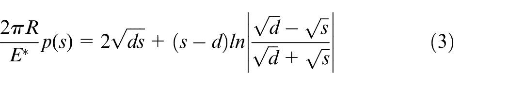
where
where the asymptotic equivalent of the contact law is
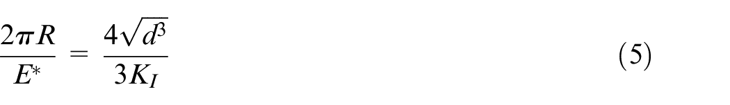
and hence
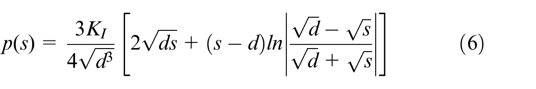
Very close to the contact edge, where
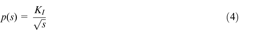
This is a very attractive, clean, tidy solution but it incorporates the result that when the observation point is very remote from the contact edge the pressure decays in a square root manner, equation (4), whereas we expect, from our observations in the last paragraph that it ought to decay in the form
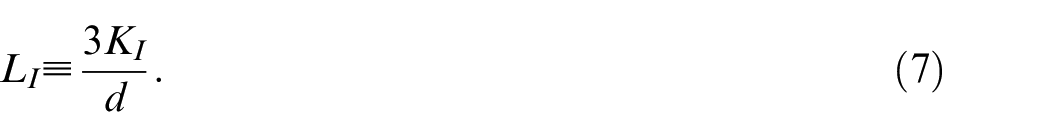
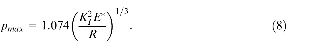
Other properties of the solution may be found. For example, the maximum value of the contact pressure, that is, the peak in Figure 2, is given by
Sharp edged punch approximation
If the edge radius of the contact-defining body is small compared with the contact half width the geometry of the punch may be approximated by a simple square-ended form, and when this pressed into contact with an elastic half plane by a normal force and clockwise moment the stress intensity factor at the left hand edge is given by. 11
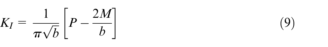
where
Example results and comparisons
We will consider now how well the method derived applies to contacts found in practical problems, and the range of loads and geometries over which the solution could be thought of as valid. The semi-infinite solution cannot sense whether the load it is subjected to arises from a normal load or a moment, so in order to see how well the solution applies to a real punch geometry the contact pressure distribution for a finite flat and rounded punch is required. The solution derived by Andresen et al. 3 was used, the contact pressure being given by:
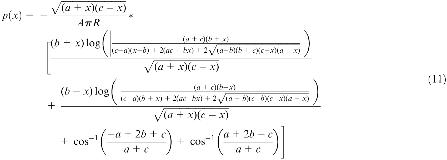
Where
where
The inputs to the problem can be arranged into three dimensionless groups,
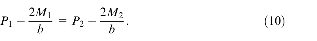
It is worth noting that equation (9) sets an upper limit on the largest possible value of
Figure 3 shows the contact pressure distribution for a number of moment-normal force loading mixtures, chosen through the use of equation (9) such that they have equivalent values of
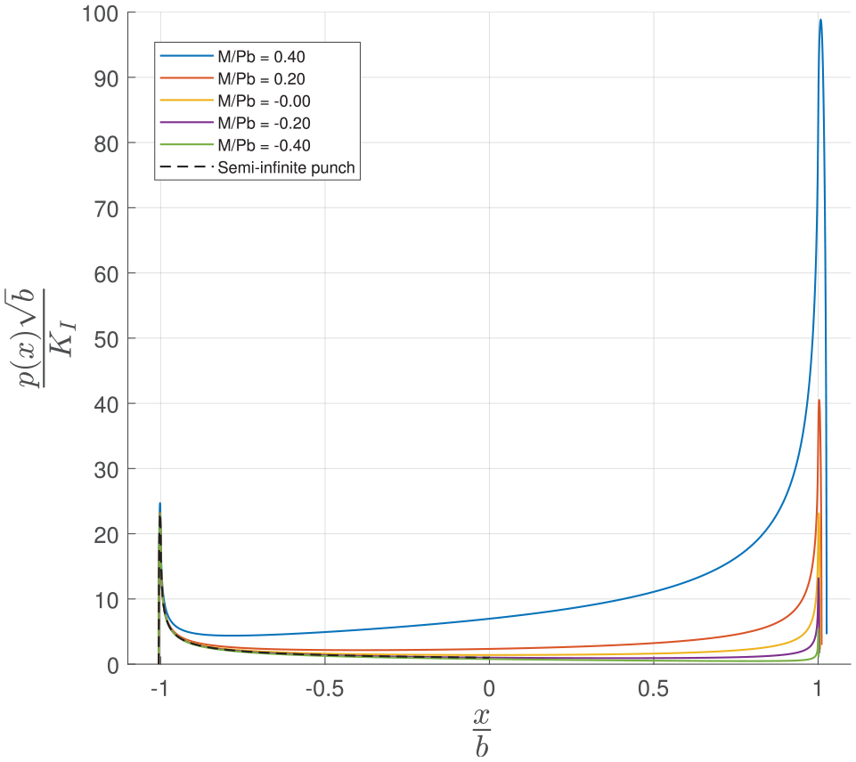
A plot of the contact pressures across the entire contact for various values of
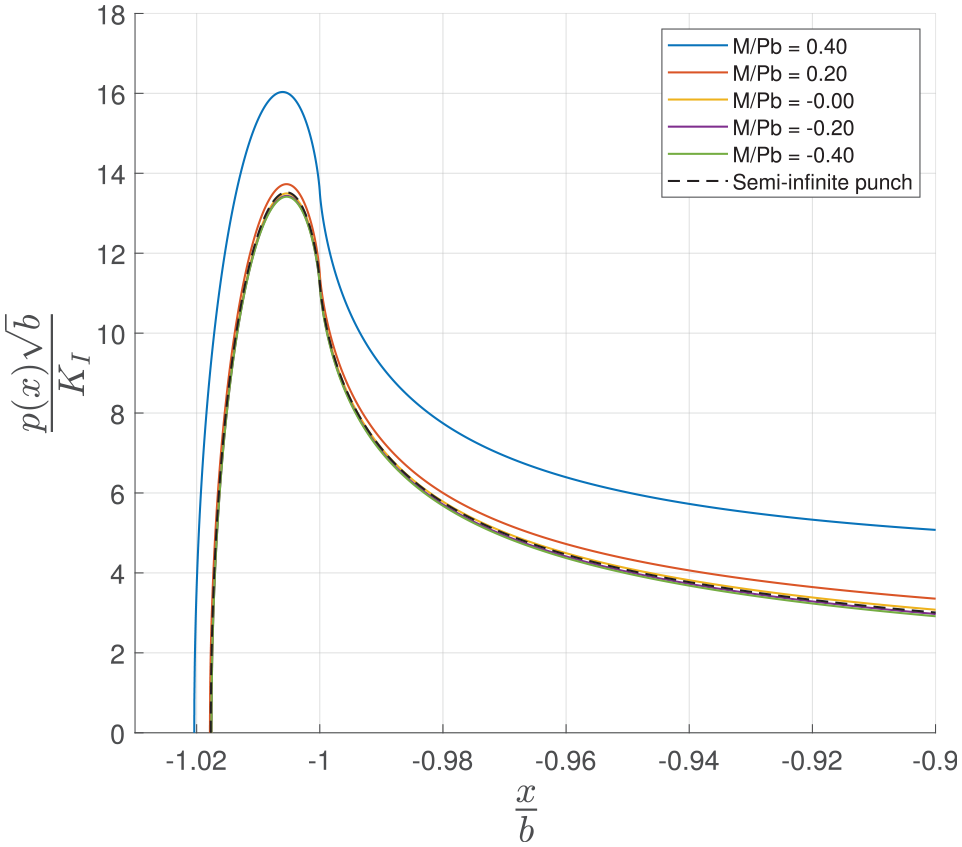
Figure 4 shows the detail of the leftmost edge of the contact pressure distribution, allowing closer inspection of the localised contact pressure in the region surrounding the corner rounding. As in Figure 3 the various solid coloured lines are solutions from the finite width punch contact pressure distribution (equation (11)), the dashed line represents the semi-infinite flat and rounded punch approximation (equation (6)). It can be seen that for the majority of load cases the solutions lie extremely close together, with the plots only starting to diverge at large values of positive moment, due to the left hand edge of the contact sensing the effect of the increased contact pressure at the right hand side of the contact (with the sense of the moment being as drawn in Figure 1, such that a positive value of moment causes an increase in contact pressure at the right hand edge of the contact).
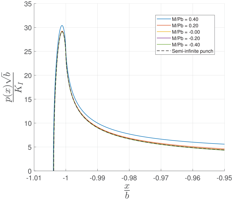
A plot of the contact pressures at the left hand edge of the contact, over a sweep of values of
Another example of the accuracy of the moment matching achievable is shown in Figure 5, This time for the rather geometrically extreme case
A further example of matching equivalent pairs ofP-M loadings, in this plot for the case
It would seem a natural next step would be to attempt to quantify the difference between the theoretical semi-infinite pressure distribution and the pressure distribution for a finite width punch over a range of loading conditions and geometries. Figure 6 shows the results of one method of attempting to measure this change. One way of characterising the near edge stress field of an incomplete contact is through the use of a square root bounded asymptotic multiplier,
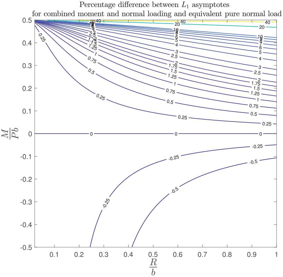
The percentage difference in the outer
Application to fretting fatigue experiments
An obvious application of this method is to the study of the effects of moments in fretting fatigue experiments. Figure 7 shows an example of a typical test rig used in Oxford for the study of fretting fatigue problems, and illustrates the typical layout of actuators. A pair of pads bear on a dogbone specimen, a hydraulic actuator at the base of the rig providing normal load. A further pair of actuators to the left and right of the specimen apply loads to it, so through the application of differential loads to each end of the specimen shear loading can be applied. The rig as built has no facilities to apply moments: only the normal load, shear load and bulk tension are controllable, but if a procedure such as the one derived in this paper is used it becomes unnecessary to be able to control the moment directly. Generally there are a couple of situations in which we may wish to account for the presence of a moment in an experiment:
The study of contacts where the prototype component is loaded with large moments
To account for the effects of moment coupling phenomenon arising from the design of the apparatus 2
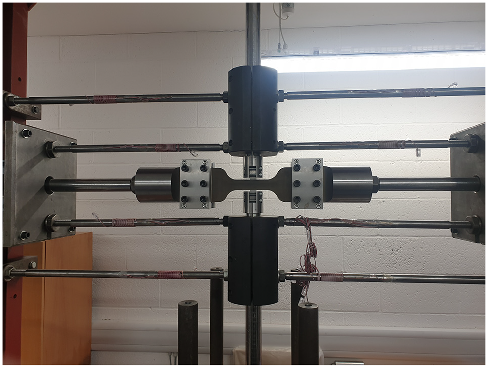
An image of the fort rig, a typical piece of test apparatus used in the study of fretting fatigue phenomenon.
As an illustrative example let us briefly consider a problem of the second kind.
As described in Truelove et al., 2 moment coupling is the generation of an undesired moment across a contact during a fretting fatigue experiment. These moments can arise from a number of sources, including deformation of the test apparatus, and the fact that it is impossible to construct a practical pad with true half plane geometry – the pad must include some form of projection which then deforms as a stubby cantilever under the application of shear load. For the fort rig illustrated in Figure 7 the load paths through the rig are a major source of coupled moments, in that the shear load is supported through leaf springs at a significant distance from the contact.
First, the coupling coefficient between the applied shear force on the pair of pads,

Therefore, through equation (9), if the prototype experiences a load set
where
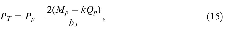
As an example consider Figure 8. This represents a case where we wish to run an experiment on a rig with a known amount of moment coupling, but where we would like to run the test under conditions equivalent to a constant normal force loading, that is, the near edge contact pressure should remain constant throughout the loading cycles. The plot shows three lines; in blue we have the idealised pressure distribution without any moment, whereas in orange we have the pressure distribution that would actually occur at the point in the load cycle where maximum moment occurs, which corresponds to the point of maximum applied shear. Through the use of equation (15) with
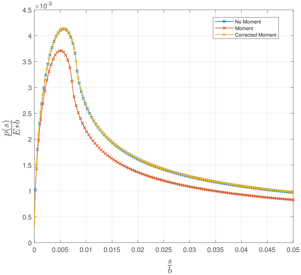
A three way comparison between the pressure distribution for a punch with no moment, a punch with a moment applied and a punch with normal load varied in a way such that the effect of the moment is cancelled out.
Conclusion
In this paper we have described a method of modelling the effect of an applied moment to a flat and rounded punch by adding a local solution for corner rounding to a solution for a sharp ended punch. It was demonstrated that the sharp punch and rounding model approximated a finite flat and rounded punch solution over a range of contact geometries. The solution for a sharp edged punch was therefore used to find a way of connecting equivalent P, M pairs for flat and rounded contacts, and it is shown that this model applies over a wide range of punch geometries and load cases.
In the formulation used here the finite punch solution is an elastically similar elastic-elastic problem, whereas the square edged punch formulation uses a rigid punch on an incompressible half plane. Both these formulations result in Dundur’s second parameter being equal to zero, so that the normal and tangential problems are uncoupled and the application of normal loading does not generate shear tractions across the contact interface.
The method outlined in this paper has practical application to fretting fatigue experiments, allowing for both the addition and removal of equivalent moments from experiments while using rigs that do not have facilities to control moment loading.
Footnotes
Declaration of conflicting interests
The author(s) declared no potential conflicts of interest with respect to the research, authorship, and/or publication of this article.
Funding
The author(s) disclosed receipt of the following financial support for the research, authorship, and/or publication of this article: James Truelove acknowledges with thanks the award of an iCASE award ref 17000027 from Rolls-Royce plc which has enabled him to carry out this work. David Hills and Luke Blades acknowledge Rolls-Royce plc and the EPSRC for their support under the Prosperity Partnership Grant: ‘Cornerstone: Mechanical Engineering Science to Enable Aero Propulsion Futures’, Grant Ref: EP/R004951/1.