
Abstract
Interior noise in high-speed trains creates passenger discomfort and fatigue. In particular, the noise generated around the gangway between carriages tends to be easily transmitted to the passenger spaces due to the large noise component in the low-frequency region. In addition, the noise from the between-cars space around the gangway exterior tends to increase significantly when the high-speed train is travelling inside a tunnel. Therefore, this study analyses the cause of the noise generated in the gangways and identifies an effective method for reducing it. First, the mechanism for noise generation around the gangways was determined by computational flow noise analysis using a simple two-dimensional cavity model. From this simulation, it was confirmed that noise is generated when air flow enters the cavity. To investigate the influence of noise reduction in the between-cars section, blocking the airflow indirectly by installing fairings or directly by using side barriers was proposed. These noise reduction methods were examined by flow noise analysis, and then applied to an actual high-speed train. The interior noise was measured, and the results show that the use of side barriers was effective in reducing interior noise by 10 dB or more. In particular, a high noise reduction effect was exhibited in the low-frequency region. Therefore, this study verifies that directly blocking the inflow into the between-cars section is an effective noise reduction method.
Introduction
Interior noise in a high-speed railway vehicle creates discomfort and fatigue for passengers. The main noise sources of high-speed trains are rolling noise due to wheel–rail interaction, mechanical noise caused by a power unit, structural noise caused by structural vibration and aerodynamic noise. The magnitude and contribution of these factors to interior noise depend on the speed of the railway vehicle. In general, it is known that aerodynamic noise increases rapidly when the speed of a train reaches 300 km h−1. In particular, around the gangway exterior or between-cars sections, flow noise develops with a complex shape, thereby generating a number of noise sources. In addition, the noise generated in the between-cars section tends to be easily transmitted into the interior by the bellows made of silicone rubber because of high-intensity low-frequency noise components. In particular, these noise characteristics tend to increase even more when driving inside a tunnel.1,2 Therefore, many studies have been conducted to reduce the flow noise of between-cars sections.
The theoretical study of aerodynamic noise began with the study of the noise generated by jet engines in the aviation sector. Compared to the noise generated by jet engines, the flow noise generated by high-speed rail vehicles is relatively small. In addition, aerodynamic noise generated from high-speed trains is caused by irregular flows around the vehicle. Experimental approaches have been carried out to analyse the cause of this noise. Through these studies, the turbulent boundary layer of high-speed trains was measured and analysed.3,4 Laser Doppler velocimeters were used in the driving vehicle to analyse the turbulent boundary layer around high-speed trains. In addition, the height and characteristics of the boundary layer with respect to the flow around a high-speed vehicle were analysed using a 1/15 scale model of a high-speed train in a wind tunnel. However, the experimental approach is insufficient to specifically analyse the noise generation mechanism around the gangway, described in this study as the ‘between-cars’ sections.
To analyse the cause of the flow noise generated in the between-cars section of high-speed trains, experimental analysis was conducted using small-scale models. 5 In this study, the characteristics of the flow in the cavity of the between-cars section were experimentally analysed through a wind tunnel test using a 1/5 scale train model. It was confirmed that approximately 45% of the flow occurs in the between-cars sections compared to the flow around the carriages. In addition, using microphone arrays to measure the noise, the main noise for each vehicle was analysed. In particular, in the case of the bellows in the between-cars section, it was confirmed that the low-frequency region has a high noise intensity. 6 This study used flow analysis to confirm that low-frequency noise is generated by the flow outside the gangways of high-speed trains but did not tackle the effect of reducing external flow noise on the interior noise.
Studies were also conducted using computational flow analysis to analyse the causes of noise generated in the between-cars sections of high-speed trains. These studies mainly examined the flow at the connection using a simple cavity model.7,8 From these studies, it was confirmed that when the inflow occurs in the cavity, flow feedback loops occur inside. The flow feedback is a flow system in which some flows in the cavity are used as inflows for making continuous flow loops. This study had the advantage of examining the effect of noise inside the cavity through a simple model. However, it did not accurately simulate the complex shape of the between-cars sections of actual high-speed trains. Moreover, this study did not suggest any effective noise reduction measure.
In addition, the main sources of noise were derived through flow analysis and wind tunnel experiments, based on a scaled-down model of a high-speed rail vehicle, and noise reduction measures were verified. 9 In this study, the main sources of aerodynamic noise were the pantograph, between-cars sections, and bogie. In particular, it was herein confirmed that the aerodynamic noise in the between-cars section was caused by the airflow entering the cavity, and reducing the gap size of the between-cars sections to reduce the air inflow of the cavity is effective. However, through the scaled model, there is a limitation in examining the effect of noise in the between-cars section of the real high-speed trains. Moreover, this study did not suggest any effective noise reduction measure.
To analyse the noise generated from a real high-speed rail vehicle, studies have been conducted to derive the main location of the noise by using a microphone array system.10,11 In addition, the effect of external noise on the interior was analysed using sound intensity probes inside and outside the vehicle. This study helped derive the contribution rate of the airborne sound to the interior noise. In addition, operational transfer path analysis, a method to analyse a vibration source during driving, was applied to further examine the effects of vibrations generated when the vehicle drives on interior noise. 12 Through these results, a study was conducted to analyse the main contributing factors to interior noise and the bottom vibration of high-speed trains.
Therefore, this study was conducted to identify effective solutions for reducing interior noise generated from between-cars sections in an actual high-speed train. The flow in the cavity was analysed using a two-dimensional (2D) model of the between-cars section of a high-speed train, and the sources of noise were identified. It was confirmed by this study that reducing the inflow inside the cavity is effective in minimising noise. To reduce the inflow to the cavity, indirect flow noise reduction using fairings was examined by computational simulation. In addition, the effect of reducing the inflow directly by using side barriers was examined by flow simulation analysis of the entire high-speed train. Finally, the effect of fairings and side barriers on noise reduction was verified by installing them on an actual high-speed train and measuring the interior noise.
Aerodynamic noise analysis theory
The aerodynamic noise in high-speed trains follows complex trajectories. When a rail train is travelling at a high speed, the flow velocity on the surface of the train becomes zero due to friction, and the flow velocity becomes the same with the velocity of the train at sufficiently long distances. In addition, laminar flow that transforms to turbulent flow complicates the flow due to viscosity and the boundary layer is called a turbulent boundary layer. Due to the complicated flow of turbulence, various noise sources are generated around the high-speed train. Therefore, in this study, various aerodynamic noise theories were used to analyse the noise from the between-cars sections of a high-speed train. Lighthill’s theory and the Ffowcs Williams-Hawkings (FW-H) equation, which are representative theories of aerodynamic noise, were used for the 2D analysis of a simple model. For three-dimensional (3D) analysis of complex shapes, the lattice Boltzmann method (LBM), which is effective in reducing computation time, was used.
Lighthill’s theory and the FW-H equation
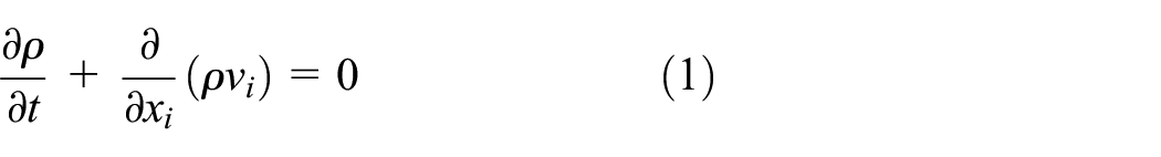
The aerodynamic noise analysis of a 2D model of the between-cars section using Lighthill’s theory is as follows.13–15 In general, the continuity equation for mass conservation in fluid mechanics is expressed as follows
where

where

Lighthill’s equation can be derived from the above equation

In equation (4),

As the solution to equation (5) is a quadrupole, it can represent the source of aerodynamic noise. The FW-H equation expresses the sound field as an array of acoustic sources derived from acoustic noise generated in the flow. The derivation of the equation is as follows.16,17 Assuming that there is a moving surface S inside the infinite fluid, the mass conservation equation inside the fluid is as follows

where

In the right side of the existing momentum conservation equation, a term is added to represent the change in stress due to the moving surface. Taking the time derivative and the spatial derivative of equations (6) and (7), respectively, and subtracting the two equations yields


The FW-H equation has three terms representing acoustic sources added to the right side of the existing wave equation. The first term refers to the turbulent noise source, the second term refers to the loading noise source, and the third term refers to the thickness noise source. Since the flow noise analysis method based on the FW-H equation needs to derive the fluid density, velocity and pressure changes, applying it to large-sized structures such as high-speed trains requires a long computational time. Therefore, in this study, Lighthill’s theory was applied to a simple 2D between-cars model, and LBM, which is useful for the aerodynamic noise analysis of complex and large-sized structures, was used for the between-cars 3D model. Aerodynamic noise analysis using LBM was found to be effective in large structures such as the pantograph of a high-speed train. 18
LBM
Lattice Boltzmann aerodynamic noise analysis is based on the movement of flow particles, which is very different from the FW-H method. In particular, the Bhatnagar–Gross–Krook (BGK) model with single relaxation time (SRT) is widely used in 3D models for analysing the flow through the collision and movement of particles. 19
In the D3Q19 3D lattice model, particle motion can be expressed as follows

In the above equation, f is the particle distribution function at spatial coordinates in space
For the Maxwell–Boltzmann distribution function, expanding the Taylor series up to the second velocity term results in equation (11)
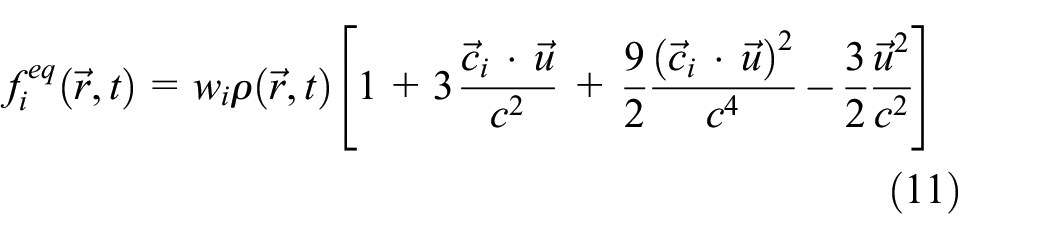
In the above equation,

The viscosity term that determines the properties of the fluid is expressed as follows

In equation (13),


As shown in the above equations, since LBM calculates the distribution function of particles around each lattice, it is effective to shorten the computation time by performing calculations in parallel when many lattices are generated like in large structures.23,24
Noise reduction design
In this section, the aerodynamic noise in the between-cars section was analysed, and an effective noise reduction method was derived. Figure 1 shows the between-cars section of a high-speed train. However, it is not easy to identify the cause of noise by measurement or observation from outside of the rail vehicle. Therefore, this section examined the flow noise using a simple model of the between-cars section and derived the main noise characteristics by computational approaches.

Between-cars section of high-speed trains.
To examine the aerodynamic flow in the between-cars section, a simple 2D model was used as shown in Figure 2. In this study, COMSOL Multiphysics 5.5 (COMSOL Inc.) was used for simple model analysis. A total of 32,884 meshes of various shapes were used to implement the analytical model. Considering the maximum operating speed of the train at 300 km h−1, an inlet flow condition of 83.3 m s−1 was set. In addition, the outlets were assumed to be under atmospheric pressure conditions, and the boundary areas corresponding to the cavity were defined as a wall.
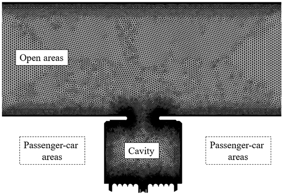
Mesh model of the between-cars section.
The shear stress transport (SST) turbulence model was used to simulate the complex flow pattern of the vehicle connection. The SST turbulence model is a widely used and robust two-equation eddy-viscosity turbulence model used in computational fluid dynamics. The model combines the k-omega turbulence model and k-epsilon turbulence model such that k-omega is used in the inner region of the boundary layer and switches to k-epsilon in the free shear flow. 25 In addition, after performing the flow analysis, the mesh for flow noise analysis was set again to match the results of the flow analysis, and aerodynamic noise in the frequency domain was subsequently performed by the FW-H method. The linearised Navier–Stokes (LNS) equation was used in this analysis. The mean flow velocity, pressure and turbulent viscosity are coupled to the LNS model using the Background Fluid Flow Coupling multi-physics feature in COMSOL.
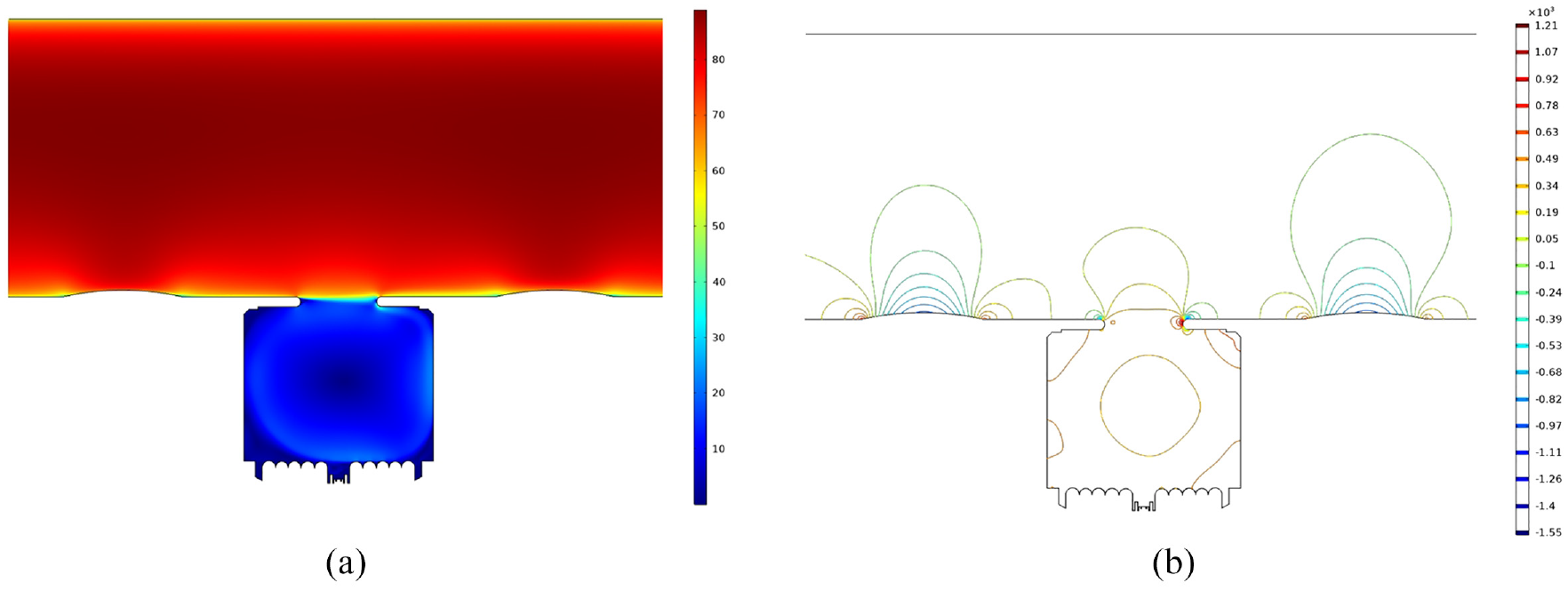
Figure 3 shows the resulting distribution of speed and pressure at a speed of 300 km h−1 around the between-cars section of a high-speed train. At this time, the flows were increased at the opposite side of the inlet due to an increase in the inflow into the cavity. In particular, a slight disturbance caused by constant flow around the between-cars sections passing through the front edge of the cavity was observed. This was transmitted downstream, colliding with the rear edge to generate sound waves, which propagate upstream and collide with the front edge. This is the flow feedback loop. It can be seen that the flow rate into the cavity was about 45 m s−1 when the flow velocity was 83.3 m s−1. In addition, it was confirmed that the pressure of the between-cars section was mainly distributed at the entrance side of the cavity and the maximum value was 1.23 × 10³ Pa.

Velocity and pressure distribution of between-cars section: (a) Velocity and (b) pressure.
Therefore, the following approaches were examined for reducing the aerodynamic noise generated in the between-cars sections. First, reducing the flow into the cavity by adding fairings was proposed. However, since the high-speed train can travel in either direction, if the fairings excessively protrude, they may increase the flow resistance and increase the noise when driving on the other direction. As shown in Figure 4, a device that can finely reduce the inflow into the cavity was set in the between-cars sections. Therefore, in this study, the changes in the flow based on a fairing protruding about 28 mm from the body plane in consideration of the resistance of the flow were examined. There were 33,049 meshes in the analytical model, and the model was accurately implemented using complex mesh shapes.

Mesh model of between-cars section with fairing.
Figure 5 shows the distribution of speed and pressure when a fairing was attached to a position that changes the air flow in the cavity. Even with fairings attached, there was very little difference in the flow into the cavity compared to the case without fairings. In particular, in the pressure distribution, the noise radiated to the outside increased via the protruding shapes of the fairing. The highest pressure also occurred at the point where the flows hit the entrance necks of the between-cars section. The pressure was slightly reduced to 1.21 × 10³ Pa compared to the case without fairings. Therefore, it was confirmed that reducing noise inside the between-cars section may not be effective and the noise emitted outside the high-speed train may be increased.
Velocity and pressure distribution of between-cars section with fairings: (a) Velocity and (b) pressure.
However, the simple 2D model has many limitations and the predicted flow noise of the between-cars section may not be accurate. The actual vehicle connection has a lot of space in the lower part and the upper part that can increase inflow. To overcome these limitations, LBM was applied by using SIMULIA PowerFLOW (Dassault Systèmes). In particular, to model the noise generated at the between-cars sections similar to real high-speed trains, the flow of the entire vehicle as shown in Figure 6 was analysed.

Whole train and between-cars section.
In this study, for the overall flow analysis of the high-speed train, a total of 124,400,000 volume meshes and a total of 21,500,000 surface meshes were implemented for the analytical model. The analysis time unit was set to 8.245 × 10⁻⁶ s. Analysis of the flow for the entire high-speed train was performed over 3 s, and analysis of the between-cars sections was performed for an additional 0.6 s. The high-speed train had 6 vehicles and 12 bogies. Each vehicle was a power distribution–type vehicle. In particular, the between-cars section had a relatively wide width. In addition, the noise analysis positions were selected based on five locations from 1.2 to 3.5 m from a point 7.5 m from the rail to specifically analyse the noise generated from the between-cars section as shown in Figure 7. In this study, the spherical side barrier was designed to block the influx of flow from the side. Through the 3D analysis, the effect of noise generation due to the inflows from the upper and lower parts as well as the side through the side barrier, which is difficult to confirm with the existing 2D model, was examined.
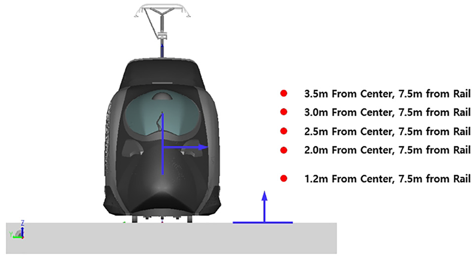
Noise analysis positions of high-speed trains.
First, the frequency characteristics for noise generation according to height without a side barrier installed are shown in Figure 8. As a result, there was no difference in spatial noise depending on the height. Moreover, it was confirmed that various noise peaks were generated in the low-frequency range from 80 to 280 Hz. For the overall noise level, it was confirmed that 74 dB (A) noise occurs at a location 7.5 m away from the rail.

Propagation noise from between-cars sections without side barriers.
The noise propagation results when a side barrier was installed are shown in Figure 9. It was confirmed that the amount of noise generated in the 280-Hz range was significantly reduced in the area where the largest difference appeared due to the installation of the side barrier. In addition, it was confirmed that from 80 to 100 Hz, the amount of noise propagated at a height of 1.2 m was the largest at 280 Hz. In addition, the overall noise was confirmed to reduce the noise emitted by 71 dB (A) by 3 dB.

Propagation noise from between-cars sections with side barriers.
To further analyse the flow noise generated at the between-cars section, vortex generation caused by the aerodynamic noise was examined as shown in Figure 10. It can be seen that the noise generated from the between-cars section flows into the empty spaces, and a number of vortices were generated as the flows hit the walls. Therefore, preventing the flow of air into the empty space between the vehicles as much as possible can reduce the noise. Figure 11 shows the result of blocking the inflow by a side barrier. The side barrier is fabricated from silicone rubber and is designed to block the space in the between-cars section. It can be seen that when there are side barriers, vortex generation, which causes flow noise, was significantly reduced. However, even if the sides were blocked, vortices were still generated in the lower and upper parts of the vehicle.

Vortex generation from between-cars sections without side barriers: (a) Upper section and (b) lower section.

Vortex generation from between-cars sections with side barriers: (a) Upper section and (b) lower section.
Noise reduction verification
In this section, the reduction of noise in the between-cars sections using both methods (fairings and side barriers) was verified by measuring the noise in a high-speed train. As shown in Figure 12, a microphone (337B02 Model; PCB Piezotronics) was installed in the gangway at a height of 1.2 m from the bottom of the vehicle. In addition, noise was measured by attaching a surface microphone (130A40 Model; PCB Piezotronics) to confirm the noise generated from outside the between-cars sections. The sampling frequency was set to 25 kHz, and data acquisition was carried out using a sound and vibration multi-channel measurement system (PAK MKII; Muller BBM). In addition, as shown in Figure 13, a fairing was installed on one of the connected carriages and side barriers were installed over the gangway connecting the carriages. Analysis of the data measured was carried out using PAK Software (Muller BBM).

Noise measurement in the gangway of the high-speed train.

Fairings and side barriers attached to the side of the high-speed train.
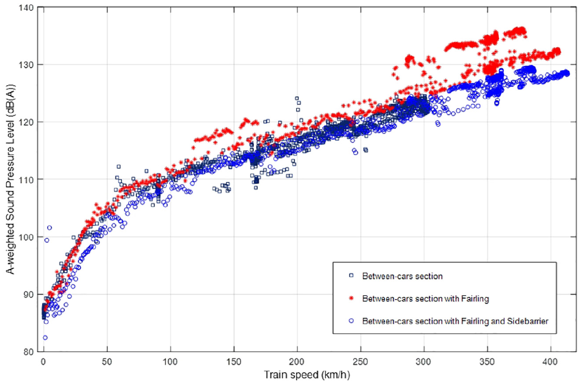
As shown in Figure 14, the train travelled a distance of 64 km between Ulsan Station and Gomo Station, and the maximum speed achieved was 300 km h−1. It can be seen from the graph that the exterior noise of the train was about 15–20 dB higher than that of the interior noise. In particular, it can be seen that both the interior and outdoor noises generated from the between-cars sections increased as the speed increased.

Train speeds and sound pressure level of the between-cars section and gangway during driving: (a) Open field and (b) Tunnel.
Frequency domain analysis of gangway indoor noise at the highest moving speed was performed. Figure 15 shows the indoor noise sound pressure levels when driving in open spaces and tunnels in 1/3 octave bands. It was confirmed that the sound pressure increased rapidly in the low-frequency region around 80 Hz when entering the tunnel. Therefore, to reduce the noise of the gangway and apply an effective noise reduction method, it is important to identify the cause of noise generated in the low-frequency region. In the previous 3D flow simulation, it was confirmed that 80-Hz noise is generated in the between-cars sections due to the flow into the cavity. However, the previous simulation results provided the characteristics of noise radiated at a location 7.5 m away from the rail, and this result was measured in the between-cars section.

Sound pressure level of the gangway in an open field and a tunnel: (a) Open field and (b) Tunnel.
As discussed previously, to reduce noise generated in the between-cars sections, it is necessary to reduce the flow into the space. Therefore, in this study, noise reduction through fairings that indirectly reduce the inflow of the cavity and through side barriers that directly block the inflow was implemented. Figure 16 shows the cavity noise reduction effect of attaching a fairing only and attaching both fairings and side barriers. It can be seen that, even when driving at the same speed, the external noise was increased by about 5–10 dB compared to driving in the open area when driving in the tunnel. In addition, even if the inflow was indirectly reduced by the fairing, it was difficult to achieve a meaningful reduction. The noise was generated because of the airflow in the between-cars section due to the attached pairing. As the pairing was composed of projecting shapes on the vehicle body, the resistance of the flow could be increased to generate noise as shown in Figure 17. These results demonstrated that the propagation noise can be increased with attached fairing. Therefore, to utilise the pairing as an effective noise reduction measure, additional studies to observe the optimisation of the shape of the flow are necessary. On the other hand, when a side barrier was installed, the noise generated from the cavity was reduced by about 10 dB at 300 km h−1. Therefore, it was confirmed that side barriers that can completely block inflow were effective in reducing noise.
Noise reduction at an inter-coach spacing with fairings and side barriers.
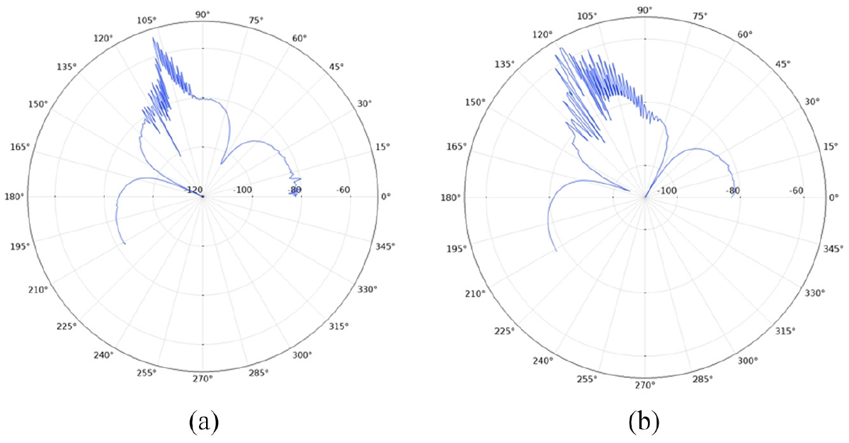
Sound propagation from an inter-coach spacing at the frequency of 100 Hz: (a) Sound propagation without fairings and (b) sound propagation with fairings.
The noise reduction in the interior space of the between-cars sections is shown in Figure 18. The effect of fairings on interior noise reduction was insignificant. In general, noise can be reduced by reducing the inflow, but the vehicle used in this study has a wide gap between vehicle connections and has an open structure allowing flows from the top and bottom. On the other hand, noise was reduced by the installation of the side barrier. The degree of noise reduction was determined by factors such as the driving environment and speed of the vehicle because of the large fluctuation range of noise. However, it can be confirmed from the results that indoor noise can be reduced by up to 10 dB by installing a side barrier.

Noise reduction at a gangway with fairings and side barriers.
The results of the frequency analysis of the interior noise in a train travelling at 300 km h−1 with a fairing and a side barrier are shown in Figure 19. It can be seen that noise was significantly reduced when a side barrier was installed. In particular, the low-frequency noise in both open areas and tunnels was reduced. When there were no side barriers, high noise increase was observed in the 80-Hz region when driving through a tunnel. As discussed in the flow noise analysis above, the noise in the low-frequency region was caused by a large number of vortices generated by the flow surface resistance on aerodynamic flow around the between-cars sections. However, it can be seen that by installing side barriers, the inflow of the vehicle connection portion was blocked, significantly reducing the noise by about 10 dB in the 80-Hz region.
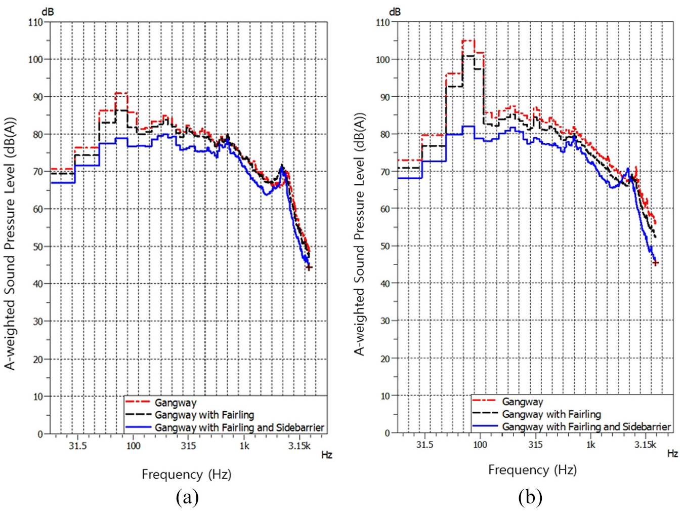
Sound pressure level of a gangway in open field and tunnel: (a) Open field and (b) Tunnel.
Conclusion
This study presents the results of interior and exterior noise measurements at the gangway of a high-speed train and the verification results for effective noise reduction measures. In this study, various methods for reducing noise in the between-cars section of a train were analysed. First, the cause of noise generated in the between-cars section was identified by flow noise analysis using a cavity model. From this flow analysis, noise reduction approaches such as the installation of fairings and side barriers were proposed. In particular, flow noise reduction by fairings was investigated using a simple 2D model. In addition, the noise generation mechanism at the vehicle connection was examined by 3D analysis, and it was confirmed that noise can be effectively reduced by side barriers. The effects of fairings and side barriers were verified by application to an actual high-speed train. From noise measurements on an actual rail vehicle, it was confirmed that the noise of the gangway can be effectively reduced by side barriers. The flow noise in the between-cars section increases rapidly when the train is driving through a tunnel, and side barriers reduced the flow noise in the low-frequency region. The results of this study can help in the design of quiet high-speed trains that allow comfortable rail travel for passengers.
Footnotes
Handling Editor: James Baldwin
Declaration of conflicting interests
The author(s) declared no potential conflicts of interest with respect to the research, authorship and/or publication of this article.
Funding
The author(s) disclosed receipt of the following financial support for the research, authorship and/or publication of this article: This research was supported by a grant (20TLRP-C146729-03) from Railroad Technology Research Program funded by the Ministry of Land, Infrastructure and Transport of Korean government and a grant from R&D Program of the Korea Railroad Research Institute, Republic of Korea.