
Abstract
When the speed of a railway vehicle increases, the level of noise inside the vehicle inevitably increases as well, which is a major cause of discomfort to passengers. The most effective method is to improve the overall noise reduction performance of a vehicle. In particular, the gangway of the railway vehicle is made of silicone rubber; therefore, its noise reduction performance is inferior to that of other components of the vehicle. Thus, it is essential to improve the interior noise performance of railway vehicles. This study aims to reduce the noise in the low-frequency region of a railway vehicle gangway. It examines the applicability of the multi-layered resonance type panel, which has not been previously applied to the bellows in railway vehicles. In particular, the transmission loss was improved by changing the structure without filling the bellows with sound-absorbing material. First, a theoretical review of the noise reduction performance of a perforated multilayer structure was performed. Based on this, the major design parameters of the perforated multilayer structure that are effective in reducing noise in the low-frequency region of the bellows were derived. Through this, it was confirmed that in the multilayered structure, the hole diameter of 1 mm was effective in increasing the transmission loss in the low-frequency region, and the transmission loss was improved at 1% of the porosity. In addition, through a simple two-dimensional analysis model, it was confirmed that the transmission loss of the porous panel was improved at low frequencies of 100 to 400 Hz. Based on this result, a gangway with perforated multilayer structures was developed and tested. Through this verification test, it was confirmed that the noise performance of 9.2 dB was an improvement in the low frequency range of 100 Hz.
Introduction
An increase in the speed of a railway vehicle also increases the noise inside the vehicle, causing discomfort to passengers. There are various causes of excessive interior noise in railway vehicles, such as the rolling noise caused by wheel-rail contact and aerodynamic noise caused by the turbulent flows around the car body. In addition, the noise characteristics vary with the driving environment, such as open or tunnel areas. Therefore, reducing the overall noise of a vehicle is limited to reducing the noise generated from a specific source in particular driving conditions. 1
Various studies have been conducted to analyze the cause of indoor noise in railway vehicles, in particular, to derive transfer functions of noise sources.2,3 However, it is not easy to apply the traditional transfer function method when using an impact hammer on a railway vehicle, owing to its large size and heavy weight.4,5 Therefore, a study was conducted to derive the cause of interior noise in railway vehicles based on their operational signals. 6 These studies confirmed that the main causes of indoor noise may vary depending on the driving environment. However, studies based on experiments have limitations regarding the design of mitigation measures because they do not suggest the mechanism that causes noise.
A study was conducted to analyze the causes of indoor noise and derive more effective countermeasures using an analytical method. Because railway vehicles have large bodies, the analysis range is wide; thus, it is not easy to analyze vehicles with the commonly used finite element method. 7 Therefore, previous studies have been conducted using image-source and ray-tracing methods, which can analyze large-scale railroad vehicles.8,9 However, this method has a limitation in that only the high-frequency region can be analyzed. Therefore, a recent method based on statistical energy analysis has been widely applied.10,11 This method is more effective for analyzing a wider frequency range than the existing method. However, there is a limit to analyzing the indoor noise generated in the low-frequency region.
To study the interior noise of railway vehicles, it is important to consider the filter effect on the transmission loss of the noise through the vehicle body. 12 Owing to this filter effect, the indoor noise of railroad cars tends to be high in the low-frequency range in most cases. However, the general sound absorbing material has a high noise reduction performance in the high-frequency region, but low characteristics in the low-frequency region; therefore, its application to the noise reduction of railway vehicles is limited.
To reduce the interior noise of railroad cars, research has been conducted on the material and structures of car body frames. Previously, car body frames were made from rigid steels, but recently, extruded aluminum frames have been widely used. Extruded aluminum materials are lightweight compared with steel car bodies; however, they are relatively vulnerable to noise. Therefore, to compensate for this, methods have been derived to change the shape of the extruded aluminum material or fill the sound absorbing material.13,14
The gangway of a train is made of silicone rubber to facilitate contraction and expansion when the vehicle runs curved lines; thus, its noise reduction performance was less than that of the extruded aluminum body. Studies on the between-car sections were mainly based on analyses of the noise source.
In particular, the analysis of the main noise source for each vehicle was performed through measurement and analysis using a number of microphone arrays. 15 It was confirmed that high levels of noise occur in the low-frequency region in the case of the between-car sections. From the results, it was observed that a low-frequency noise was generated by the turbulent flow outside the gangway. This study focuses on identifying the mechanism of noise generation using a flow analysis of the between-car sections of a railway vehicle.16–18 Many studies have been conducted to reduce noise by blocking inflow to the between-car sections. However, studies suggesting specific noise reduction measures are insufficient.
There is a limit to reducing the low-frequency noise generated by the gangway of a railway vehicle using sound absorbing material. Therefore, to compensate for this, an active noise control method was proposed. In particular, a method was proposed to control low-frequency noise in a limited space. 19 This method was effective in special cases where a specific single frequency was prominent, such as engine noise of an aircraft and low-frequency road noise of a vehicle. In addition, active noise control was applied to a limited position, such as the position of the driver’s ear in the cab of a train. 20 However, unlike the cab, the passenger room has a large space and noise occurs in a wide frequency range; therefore, there is a limit to applying noise control technology specific to a limited location. The between-cars section of the railway vehicle is an area where noise is generated in a low frequency range, especially while passing through a tunnel. Therefore, it was confirmed that the noise in the low-frequency region, which rapidly increases while passing through a tunnel, can be blocked by blocking the inflow of noise through the side barrier and pairing. 21
This study aims to reduce the low-frequency noise of a railway vehicle gangway. In particular, in this study, a new approach was adopted to improve the transmission loss in a specific frequency domain by using a multilayer resonance panel, which has not been previously applied to the bellows of railway vehicles. First, a theoretical review of the noise reduction performance of a perforated multilayer structure was performed. Based on this, the major design parameters for the perforated multilayer structure were derived to effectively reduce noise in the low-frequency region of the gangway. This study confirms that a porosity of approximately 1% in the two-layer structure was effective in improving the noise performance in the low-frequency 100 Hz region. Based on this result, a verification test was conducted on a gangway with a perforated multilayer structure, which improved the noise performance in the low-frequency region. This study confirmed that the transmission loss can be increased in the low-frequency region through the internal perforated structures even if a sound absorbing material is not used inside the bellows.
Theory of transmission loss of perforated multilayer panels
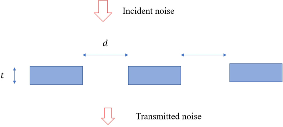
This section examines a method to reduce noise in the low-frequency region transmitted through the bellows based on basic acoustic theory. First, the shape of the bellows can be expressed, as shown in Figure 1, by simply observing the concept of the incident sound. In this case, the sound is transmitted from the outside to the inside through bellows made of silicone rubber. The transmission loss of sound in the case of a single plate is as follows. The bellows were assumed to be flat, nonporous, and flexible for simple simulation.
22
In this case, the impedance of the partition (

where

Internal structure of the bellows.
Based on this equation, the impedance of the simple and flat bellows panel can be expressed as shown in Figure 2. In this study, the specific gravity of the bellows specimen was measured according to ASTM D792 (Standard Test Methods for Density and Specific Gravity (relative density) of Plastics by Displacement). An electronic densimeter (Alfa Mirage, Japan) was used to conduct the density measurements. The density of the test sample for the connecting membrane was 1.266

Impedance of bellows panel with a variation in thickness.
In addition, a case in which the inside of the bellows is implemented in two multilayered structures, such as the internal structure of the actual bellows, can be considered. In this case, assuming that the medium is air, the pressure amplitude transmission coefficient (
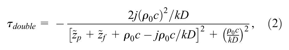
where D is the distance between the two panels, and k is the wavenumber. In the case of a double-layered panel instead of a single-layered structure, transmission loss should be improved by 6 dB or more, owing to the effect caused by increasing the thickness. However, even in the case of a double panel, the transmission loss decreases sharply in the mass-air-mass resonance frequency domain. Assuming that the distance between the air layers inside the two panels of the bellows is 133 mm, the mass-air-mass resonance frequency was 232 Hz. The transmission loss has a low limit in the low-frequency region, owing to the resonance of the natural vibration frequency of the panel or the mass-air-mass resonance frequency of both panels in the low-frequency region. Therefore, this section examines a method to improve the transmission loss in the low-frequency region, based on a porous hole, when reinforcing the inside of the bellows.
First, a simple structural panel with a porous hole can be expressed as shown in Figure 3. t is the thickness of the panel, and d is the diameter of the hole. The impedance of the hole can be expressed as follows: 24


where
Pressure and particle velocity in a single perforation.
In addition, we have to consider that additional energy reduction occurs in the porous hole. This is generated by viscous dissipation on the surface of the micro-perforated plate (MPP) and by the extra air masses, and is called end correction. As air passes through the hole, a distorted flow is created on the MPP surface.
25
When the panel thickness and the hole diameter are shorter than the sound wavelength, the air in the hole acts as a piston. This piston pushes air on both sides of the hole, and the panel thickness increases by 0.85 d.26,27 Considering the end correction, the specific impedance of the MPP (

where p is the porosity of the MPP and
Based on the above equation, a simple simulation was conducted for the impedance of a bellows panel. First, to investigate the effect of hole size on the impedance, the impedances for hole diameters of 1, 2, and 3 mm were examined, as shown in Figure 4. The simulation was performed in the frequency range of 20–4000 Hz. The results show that the impedance increases with an increase in frequency. In addition, in the high-frequency region, it was confirmed that a hole with a large diameter has a high impedance. However, it was confirmed that the transmission loss in a hole with a diameter of 1 mm has an optimal value in the low-frequency region below 200 Hz. In addition, to examine the effect of porosity on the impedance of a perforated panel, the impedance values for porosities of 1%, 2%, and 3% were reviewed, as shown in Figure 5. The results confirmed that the lower the porosity, the higher the transmission loss in the entire frequency domain. Therefore, in this study, a method to implement a porous structure inside the connecting membrane was examined based on a porosity of approximately 1% in a hole with a diameter of 1 mm.
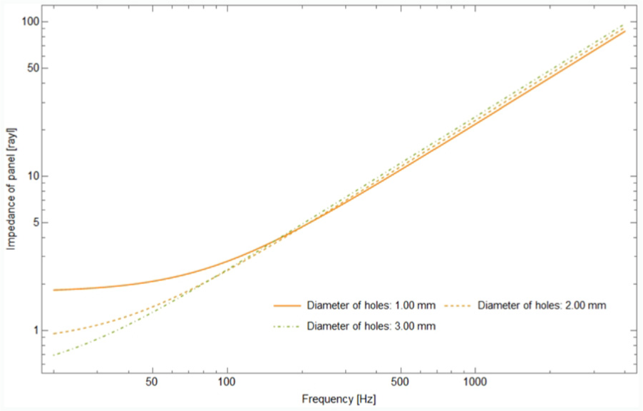
Impedance of perforated panels with various hole diameters.

Impedance of perforated panels with various porosities.
Design of improved gangways
Material property analysis
This section presents a method to improve the impedance by reinforcing the bellows panel in the space inside the bellows. The gangway of railway vehicles is composed of silicone rubber; therefore, material property analysis of silicone rubber, which is a basic material of the bellows, was performed. First, a test specimen was obtained to represent the density, specific gravity, Young’s modulus, and Poisson’s ratio, which are material properties for noise analysis. The specimen had a rectangular shape with a width, height, and thickness of 15.16, 9.86, and 2.63 mm, respectively.
In addition, when an external force was applied to the specimen of the bellows, a measurement of Young’s modulus related to physical deformation was performed. This study was performed based on ASTM D4065 (Standard Practice for Plastics: Dynamics Mechanical Properties: Determination and Report of Procedures), an international standard for measuring Young’s modulus. The measured results confirmed that the storage modulus has a value of 65–95 MPa.
The measurement of Poisson’s ratio was set up on a universal testing machine and measured using a video extensometer. The analysis speed was 10 mm/min, and the average value of three measurements was obtained. Thus, it was confirmed that the measured Poisson’s ratio of the silicone rubber specimen was 0.5.
In this study, multiple holes were used to improve the noise reduction performance in the low-frequency region of the bellows. To this end, an experiment was performed to measure the flow resistance of a silicone perforated specimen. When the perforated specimen was present in the air-layer medium for sound transmission, there was a resistance to the propagation of sound. The flow resistance, which indicates the degree of sound propagation resistance, is a major influencing factor in analyzing the noise reduction performance of the perforated panels. The flow resistance is expressed as the ratio of the real part to the pressure drop and the decrease in the flow rate when sound is transmitted through a unit-thick plate. To measure the flow resistance, a method was used to specify the pressure fluctuation, before and after passing a specimen, by injecting a direct flow in a duct or via an indirect acoustic method using an impedance tube.28,29
The direct method measures the decrease in sound pressure and flow velocity by injecting a flow at a constant speed. Because this method measures the pressure change of the flow before and after passing through the specimen, it can be easily and intuitively implemented using a device that flows at a constant flow rate. However, it is not easy to implement this flow condition in the tube. Therefore, in this study, the flow resistance of a perforated specimen was measured via an indirect measurement method using an impedance tube.
To measure the flow resistance, the experimental equipment was constructed with a specimen inserted in the center of the impedance tube. In addition, as shown in Figure 6, two microphones were placed at a particular distance between the specimen and the speaker. Based on the sound pressure generated by the speaker, the flow resistance experienced by the specimen can be measured indirectly using the sound pressure measured by the two microphones. 30

Impedance tube measurements.
In this experiment, the flow resistance was measured using a specimen with a perforation diameter of 1 mm and a porosity of 1.07%. Measured flow resistance values were observed between 4
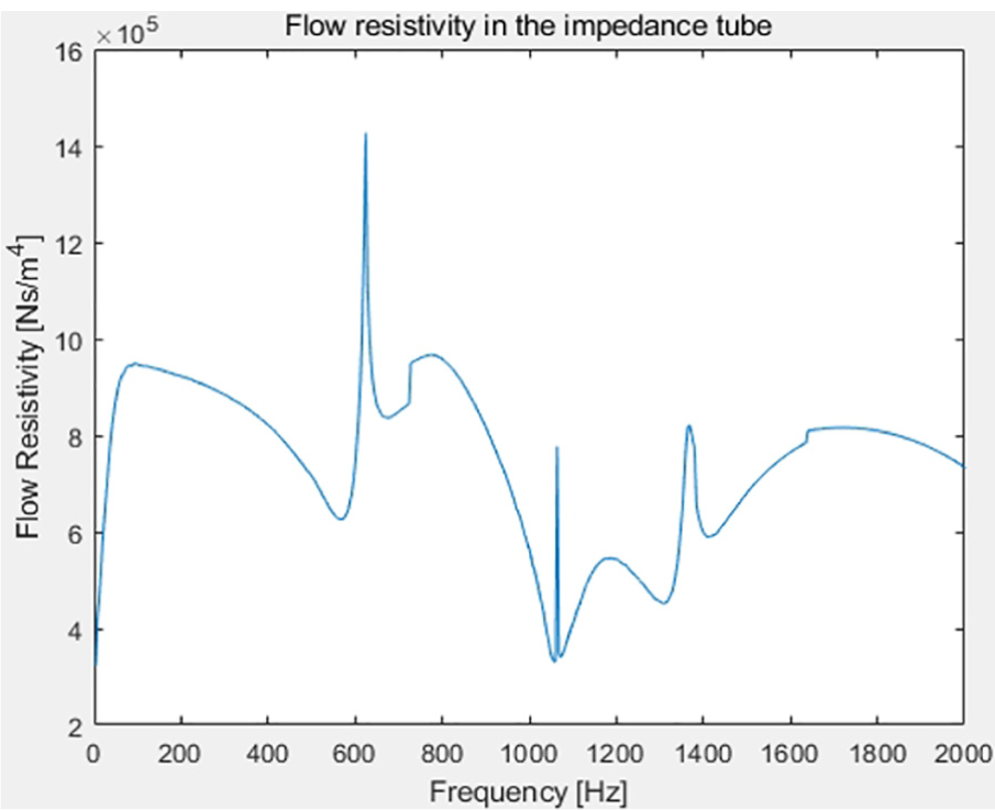
Flow resistivity analysis.
Simulation analysis of transmission loss
Based on the properties of silicone rubber as a component of the bellows and the measured flow resistance in the form of perforation, a method to improve the noise performance of the connecting membrane was derived using computational analysis. First, to simplify the analysis of the bellows, a two-dimensional simulation model was derived, as shown in Figure 8. The bellows were implemented in a variety of curved shapes to facilitate contraction and expansion, in order to smoothly run the curved line of the railway vehicle. In addition, noise generated from the outside of the railway vehicle flows into the interior through the bellows. Therefore, it is essential to improve the noise reduction performance of the bellows to reduce the noise generated at the gangway portion of the railway vehicle. To achieve this, the sound absorbing material is filled in the bellows; however, the driving flexibility of the vehicle may be impeded. Therefore, this study examined the use of an internal multilayer structure.

Multilayers in bellows.
Because the bellows shape curves to the outside, transmission loss analysis reflecting the actual model is required for a more accurate prediction. Therefore, the effect on the transmission loss was reviewed using the numerical analysis software COMSOL (COMSOL Inc.). For the analysis, it was assumed that the outside and inside of the bellows were set as the air layer, as shown in Figure 9, and a sound pressure of 1 Pa from the outside was incident in the frequency range of 20–3000 Hz. In addition, the frequency interval was set to 20 Hz to analyze the noise change characteristics according to the frequency. The number of meshes in the analysis model was 6855, and various types of meshes were used to effectively implement the curved bellows. In addition, the properties of the derived silicone rubber material were applied to the bellows to facilitate an accurate analysis.

Analysis mesh models.
To determine how to improve noise performance in the low-frequency region of the connecting membrane, the results of the analysis of noise propagation for the existing connecting membrane were first examined. Figure 10 shows the results of noise reduction in the bellows when noise of 230 Hz and 2000 Hz is transmitted through the existing bellows. As shown in the results, high levels of noise are generated from the outside of the bellows, and the noise is sequentially reduced while passing through the curved part of the bellows. In the case of the existing bellows, it was confirmed that even in the low-frequency region of 260 Hz, the noise was reduced whenever sound passed through the bellows panels. However, it can be seen that the reduction effect on the transmission loss did not increase significantly even when the frequency was increased to 2000 Hz. Moreover, because the inner part of the bellows is composed of one space, it can be observed that noise propagates through the air layer inside.

Sound pressure level of existing bellows (dB(A)): (a) 230 Hz and (b) 2000 Hz.
To determine how to improve the noise performance in the low-frequency region of the bellows, the results of the noise propagation analysis for the single multilayered bellows were examined. Figure 11 shows the result of noise reduction in the bellows when noise of 230 Hz and 2000 Hz was transmitted through the single multilayered bellows. In particular, it can be seen that in the 260 Hz region, the effect of transmission loss is rapidly degraded due to “mass–air–mass resonance.” On the other hand, in the 2000 Hz region, the noise is sequentially reduced while passing through the curved part of the bellows. Moreover, because the inner part of the bellows is composed of one space, it can be observed that noise propagates through the air layer inside.
Sound pressure level of bellows with single multilayers (dB(A)): (a) 230 Hz and (b) 2000 Hz.
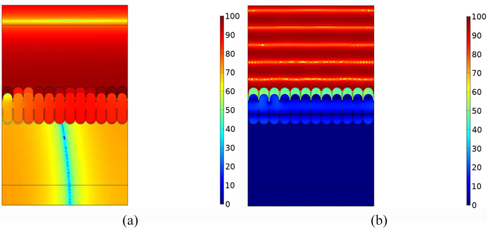
As shown in Figure 12, high levels of noise are generated from the outside of the double multilayered bellows when noise of 230 Hz and 2000 Hz was transmitted. At this time, it can be seen that in the 260 Hz region, the effect of transmission loss almost disappears due to “mass–air–mass resonance.” On the other hand, in the 2000 Hz region, it can be seen that the noise is reduced by transmitting through each bellows panel.

Sound pressure level of bellows with double multilayers (dB(A)): (a) 230 Hz and (b) 2000 Hz.
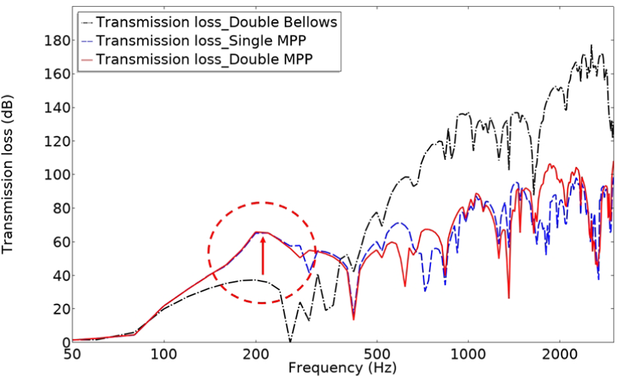
The analysis result of the performance of noise reduction through transmission loss by implementing a multilayered structure inside the bellows is shown in Figure 13. The results confirmed that the effect of noise reduction increases in the region of 500 Hz and above when the multilayer structure of the inside of the bellows was implemented. This is because noise was additionally reduced through the multilayer structure when the noise was transmitted through the inside of the bellows. Therefore, it can be observed that the multilayer structured bellows exhibits the best noise reduction performance. However, even though the effect of noise reduction was high in the high-frequency region of 500 Hz and above, it was inferior in the relatively low-frequency region.

Transmission loss of various multilayered bellows types.
In addition, it can be seen that there are many local minima, which lower the transmission loss of the bellows. The bellows has multiple natural frequencies; at the natural frequency, the transmission loss is rapidly lowered due to resonant vibration. To improve the transmission loss of the bellows, the double-layered structures on the side and top of the bellows were reinforced as quadruple-layered structures. The inside cavity of the bellows has various air cavity distances, from 133 to 45 mm. The mass-air-mass resonance frequencies were calculated as 232 and 400 Hz, respectively. From the simulation results, it can be observed that in the case of the panel with double reinforcement inside, the transmission loss rapidly decreases at approximately 230 Hz.
To improve the noise reduction performance in the low-frequency region of the bellows, based on the multilayered structure inside, a number of holes were implemented in additional panels inside the bellows. The diameter of the holes inside the bellows was set to 1 mm, and the porosity was implemented at 1%. This was additionally applied to the multilayer structured space inside the bellows, and compared with the result obtained without the application of the holes, as shown in Figure 14. From the comparison results, it was confirmed that when additional holes are applied, the noise reduction performance is improved in the low-frequency region of 500 Hz and lower. This result confirmed that in the case of inner panels with perforations, the transmission loss was significantly reduced, compared to the results owing to the mass-air-mass resonance effect without perforations. In particular, in the region below 500 Hz, no difference in the results was observed when one or two panels of the space inside the bellows are supplemented. It was confirmed that the noise reduction performance in the low-frequency region can be improved by implementing the holes. However, it can be observed that the noise reduction performance was lower in the high-frequency region when the hole was implemented.
Transmission loss of multilayered bellows and microperforated bellows.
Designed bellows verification test
Verification test setup
To realize the inside of the bellows in a porous multilayer structure, a verification test for the effect of noise reduction was performed. In the case of implementing a multilayered structure inside the bellows, the production cost was reduced by using a fixing pin that is currently used. Through this internal multilayer structure, the existing connecting film was divided into three spaces instead of one. To improve the noise reduction performance in the low-frequency region, a small hole of a particular size was drilled into the inner panel, as shown in Figure 15. The middle layer of the bellows has the largest area, and both ends have a relatively small area.
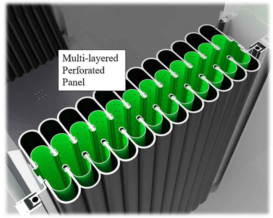
Bellows with microperforated multilayers.
A noise measurement was performed based on measurement and analysis criteria, 31 which are widely used to measure the noise reduction performance of the bellows. The reverberation chamber method was used to calculate the sound absorption rate and transmission loss for a test membrane using the reverberation time. This is based on a case where the acoustic energy density according to the space in the reverberation chamber becomes the same diffuse sound field at any point. The test area of the bellows was calculated based on the horizontal incident area. In this experiment, the acoustic attenuation index of the bellows was calculated based on the difference in the average sound pressure between the sound source and receiving rooms, the area of the sample, and the sound absorption power of the sound receiving room.
As shown in Figure 16, a test bellows was installed between the two reverberation chamber spaces. In one space, a sound source (MicroVee speaker, Velodyne, USA) was placed. In addition, in each room, five noise sensors (B & K, Denmark) were installed at a height of 1.5 m to measure the noise generated. This experiment focused on the noise reduction performance in the bellows part of railway vehicles. However, to facilitate the movement between the passenger cars, a passage in the central area of the bellows was formed. Accordingly, a sound-insulation wall with a thickness of 95.5 mm was installed to prevent the sound source from propagating through the bellows passage.
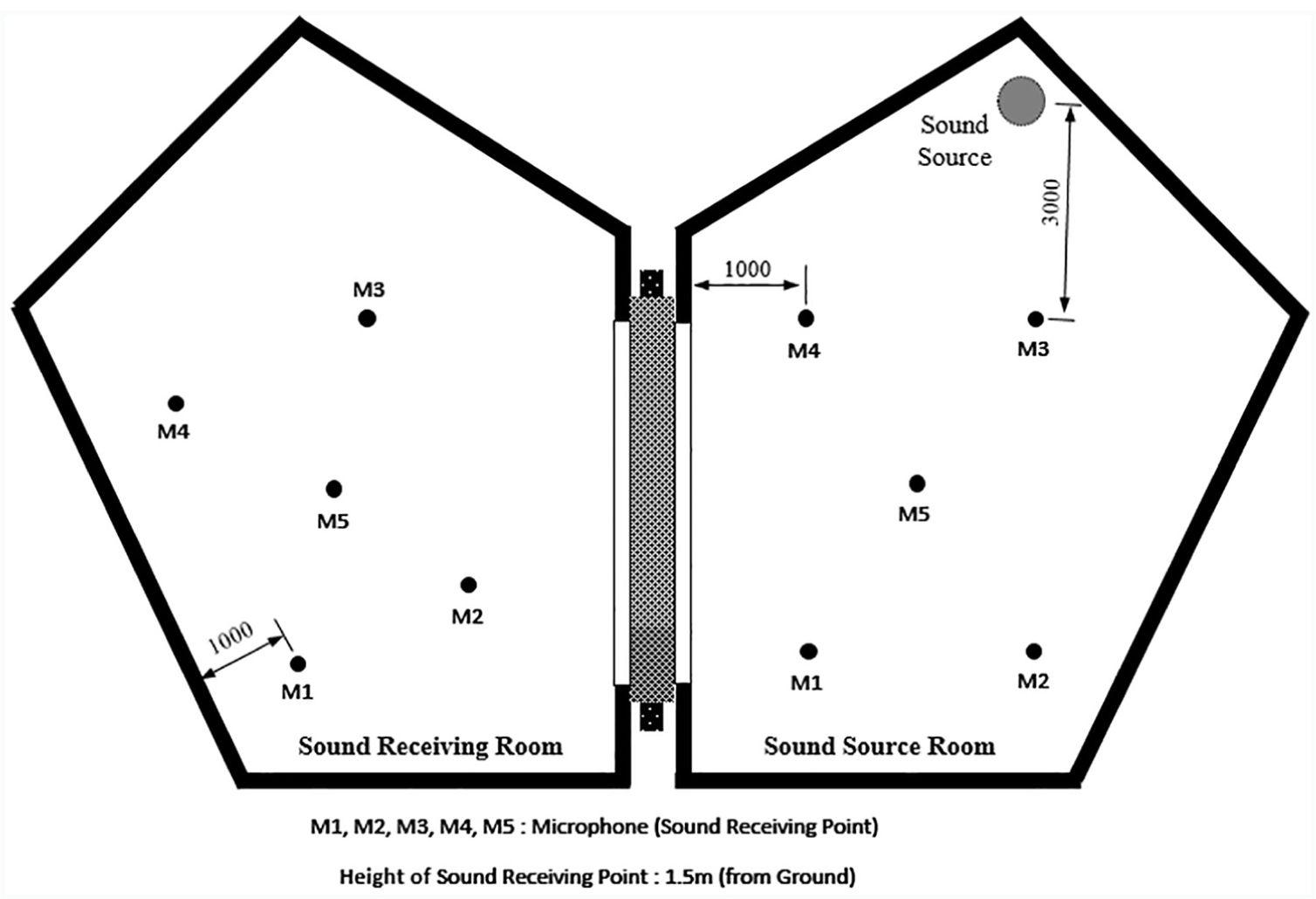
Sound source reverberation test room.
Results and discussions
Figure 17 shows the results of the measurement and analysis of both the existing bellows and the designed bellows with an interior made of a perforated multilayer structure. First, in the case of the existing bellows, the overall noise reduction index was 29 dB, and it was confirmed that the noise reduction performance was significantly low in the low-frequency region below 200 Hz; the noise reduction performance exhibited a modest increase as the frequency increased. In particular, it can be observed that in the region below 200 Hz, the noise reduction index remains below 13 dB. However, when the interior was made of a perforated multilayer structure, it can be observed that the overall noise reduction index is 32 dB, which improves the noise reduction performance by 3 dB, compared to the previous case. In particular, the degree of noise improvement in each frequency domain was examined, as shown in Figure 18, by subtracting the noise blocking index of the existing bellows from that of the improved bellows in each frequency domain. From the reviewed results, it can be observed that the noise reduction index was improved to 9.2 dB in the 100 Hz range, which resulted in the highest reduction performance. It was also confirmed that a noise reduction performance of 7.9 dB was obtained even in the low-frequency region of 125 Hz. Overall, it was confirmed that the noise reduction performance was high in the low-frequency region below 315 Hz; thus, the multilayer structure to which the holes were added induced an effective noise blocking result in the low-frequency region. However, in the high-frequency region, the degree of improvement was low, especially at 2500 Hz and 3150 Hz—the performance was lowered to 0.5 dB or less. In general, a porous panel is designed to increase the sound absorption rate, and it provides the advantage of improving the sound absorption rate at a specific frequency through design parameters, such as porosity and hole diameter. Moreover, the large number of holes causes a disadvantage in that the effect of increasing the transmission loss of the high-frequency range is inferior. However, when a general panel without holes is used inside the bellows, the transmission loss decreases in the low-frequency region, owing to the resonance phenomenon. Therefore, it was confirmed that the transmission loss was improved in the low-frequency region when a porous panel was implemented, as in this study.

Verification test of bellows with microperforated multilayers.

Improvement of transmission loss in the frequency domain.
Conclusion
This study aimed to improve the noise performance in the low-frequency region of bellows in railway vehicles. First, a theoretical analysis of the transmission loss in the multilayer structure and perforation hole was performed. The transmission loss was analyzed based on the various thicknesses of the plate, and the effects of the hole and porosity on the transmission loss were examined. Through this analysis, it was confirmed that the transmission loss was improved in the low-frequency region when the bellows was arranged in a double structure with porosity of 1% in a hole having a diameter of 1.00 mm. In addition, the physical properties of the silicone rubber material, which was the main material for the production of the bellows, were analyzed, and the flow resistance was measured for noise performance analysis. In addition, through the two-dimensional model of the bellows, a transmission loss analysis for various multilayer structures and perforated structures was performed. In particular, it was confirmed that the application of the porous hole prevented the reduction in the transmission loss due to the “mass–air–mass resonance” effect when compared with the model in which the bellows was implemented in a multilayered structure without holes. These results confirmed that the noise reduction performance in the low-frequency region can be improved when a number of holes are applied in the bellows.
Based on these results, the actual size of the bellows was fabricated, and a comparative test for noise reduction performance was performed with the existing bellows in the reverberation chamber. The measured results confirmed that the noise reduction performance of the perforated multilayered structure was improved by more than 3 dB as a whole, compared with the existing bellows. In particular, it was confirmed that the noise reduction performance of 9.2 dB was an improvement, compared with the conventional bellows at a low frequency of 100 Hz. The gangway part of the railway vehicle generates noise in a high-low-frequency region when driving in a tunnel. Therefore, it was confirmed that the bellows developed in this study has high noise reduction performance in the low-frequency range. In particular, it is noteworthy that the transmission loss of the bellows was improved by changing the structure without using a sound absorbing material in this study. This can be considered to increase the applicability because it facilitates the contraction and expansion of the bellows during curved driving.
Footnotes
Handling Editor: James Baldwin
Declaration of conflicting interests
The author declared no potential conflicts of interest with respect to the research, authorship, and/or publication of this article.
Funding
The author disclosed receipt of the following financial support for the research, authorship, and/or publication of this article: This research was supported by a grant (20TLRPC146729-03) from Railroad Technology Research Program funded by the Ministry of Land, Infrastructure and Transport of Korean government and a grant from R&D Program of the Korea Railroad Research Institute, Republic of Korea.