
Abstract
Curve squeal noise is one of the most prominent noises among railway noises. High levels of noise are generated when a train passes through curved sections, resulting in several complaints from the residents and vehicle passengers. To mitigate this problem, the squeal noise was attempted to be mitigated by laser cladding the composite material on the head of the rail. First, the effect of the negative gradient of the coefficient of friction on the squeal noise was theoretically examined. A simple model analysis indicated that the vibration of the wheel increased rapidly when the vibration system involved instability characteristics. In addition, the change in the friction coefficient owing to the local coating of the rail with a low friction material was investigated using a roller rig test equipment. The results demonstrated that the negative friction coefficient did not occur when the contact position between the wheel and rail was locally coated. Furthermore, the effect of the low friction local coating on the squeal noise in the curve section was examined in operational rails. The comparison of the results obtained before and after the local coating confirmed that the local coating of the rail can effectively reduce the squeal noise.
Introduction
Curve noise is one of the most prominent noises among railway noises, and high levels of noise are generated when a train passes through curved sections, resulting in several complaints from the vehicle passengers. 1 Furthermore, the squeal noise is a major complaint of the track-side residents, as the high noise at high frequencies is perceived as a significant annoyance. In general, squeal noise is generated when a railroad vehicle passes a curved rail section; specifically, noise levels of 100 dB or more are emitted at a distance of approximately 10 m from the center of the track, and one or several pure sounds occur in the frequency range of approximately 400 Hz to 10 kHz. Moreover, it is known that squeal noise mainly occurs in the curve sections with a track radius of less than approximately 300 m, and the noise level is considerably high when the ratio of the axle distance to the curve radius is less than 100 m. 2
Various researchers have attempted to reduce the squeal noise, primarily by reducing the damping coefficient of the wheels or ensuring that the slope of the creep rate is nonnegative to mitigate the instability of the vibration system. These solutions are based on the fact the instantaneous noise at high frequencies included in the squeal noise are usually caused by the system instability. Consequently, to reduce the squeal noise, a widely used method involves employing an elastic wheel that reduces the vibration of the wheel or using a friction modifier that reduces the friction at the contact position between the wheel and the rail. 3
To reduce the noise between a wheel and rail, it is effective to reduce the stiffness and increase the damping. To this end, resilient wheels can be applied to increase the damping by inserting a rubber element between the tread and the inner part of the wheel. 4 Using this approach, the wheel web can be isolated from the tread, and some additional damping is introduced to the wheel. The resilient wheel has been applied in light rails and tramways. 5 However, this approach is expensive because the related technology must be applied to all the wheels to obtain significant results. In addition, the operators are reluctant to adopt this system as it increases the cost of maintenance. In addition, in the event of a wheel defect, critical accidents such as derailment and train overturning may occur.
It has been observed that curve squeal occurs considerably less during wet weather. Therefore, to reduce the squeal noise, friction reduction materials have been used to reduce the friction between the wheel and rail on the rail curves. Grease and water are the most widely known friction reducing materials and can be used to effectively reduce the coefficient of friction. 2 However, it must be ensured that the employed lubricants do not lead to a loss of adhesion, as such a scenario poses a severe safety risk. Grease reduces the coefficient of friction to less than 0.2 and is therefore normally only applied to the rail gauge corner or wheel flange. It is possible that the use of grease reduces the occurrence of squeal by modifying the curving behavior, that is, reducing the angle of attack, 6 even though it may not be the primary cause of the squeal noise. However, the use of grease is limited because harmful substances may be released to the environment along the track. As a non-polluting alternative, water mist sprays have been used to eliminate squeal, and satisfactory results have been attained. However, such sprays only have a temporary effect on the adhesion levels, and it is difficult to know the exact periods of frost for maintaining the mist on the rail. Furthermore, the water spraying machine has the disadvantages of frequent breakdowns and high maintenance cost.
Considering this background, in this study, the authors investigated an approach to reduce the squeal noise by permanently reducing the frictional force at the contact position between the wheel and the rail by using laser cladding. Specifically, laser cladding can be used to reduce the friction at a specific location by adhering powder having low frictional properties to the surface of the rail through hot welding. In this work, first, a theoretical analysis was performed to examine the effect of the reduction of friction coefficient on the system instability. In addition, a small-scale wheel rail simulation test equipment was used to conduct a friction coefficient measurement test by selecting a low friction material that could be coated on a rail. In addition, the noise reduction effect was examined by conducting a vehicle noise measurement test using an actual curved rail coated with a low friction material.
Theoretical approaches
This section describes the theoretical investigation regarding the cause of the curve noise, performed considering a simple wheel and rail contact mechanism. First, the process of squeal noise generation when passing through a curved section of a railway vehicle was examined considering the contact between the wheel and the rail.
Specifically, when the wheel travels in contact with the rail, a small contact area is generated between the wheels and the rails, because of the elasticity of the two objects. 7 In this regard, various studies have analyzed the contact between curved wheels and rails. In particular, nonlinear train-structure interaction was considered to analyze the contact between the wheel and the rail. 8 In this study, the solution of the system equation was derived using an optimized algorithm, and verification was performed through comparison with actual experimental data. In addition, a study was conducted to examine the contact problem between the wheel and the rail using elastic force. 9 Through this study, parameters to describe the surface of the wheel and rail were derived. In addition, through the combined nodal and non-conformal contact approach, the analysis of the contact surface between the wheel and the rail for various curves was performed. 10 Moreover, when the wheel experiences traction, it tends to rotate slightly faster than the rail. Therefore, in the small contact area, the wheel and the rail exhibit a small difference in the relative speed. The longitudinal creepage is a non-dimensionalized value obtained by dividing the relative speed difference by the average velocity of the contact surface.11,12 In this sense, the creep forces are essentially friction forces.
In addition, in the front contact section in the traveling direction of the wheel and the rail, both the contact points of the wheel and the rail are moved back owing to the rolling in the same contact position. Furthermore, slipping occurs in the other contact surface sections. At the contact surfaces of the wheel and rail, regions of adhesion and slip occur simultaneously. 13 In addition, the difference in the relative speed between the wheel and the rail causes elastic deformation, and the local frictional force in the contact area reaches its maximum value. When this limit is exceeded, slip occurs in the entire contact area between the wheel and the rail.
With the increase in the creepage, the adhesive area decreases. In extreme cases, the slip area may occupy the entire contact area, in a phenomenon known as saturation. However, it is usually recognized that “dynamic” or “sliding” friction coefficients are smaller than “static” ones. Usually, the friction coefficient depends on the sliding velocity, and it decreases as the velocity increases. Thus, as the creepage increases beyond the saturation point, the creep force again reduces in amplitude.
When the vehicle passes through the curved part, the axle is designed to drive the center of the rail by the slope of the wheel; however, if the radius of curvature is small, an attack angle occurs between the axle and the rail. 14 This angle depends not only on the radius of the curve, but also on the shape of the wheel, bogie structure, speed, and track profile. If the attack angle is present between the wheel and the rail, the axle moves in the lateral direction, leading to the generation of a creep force owing to the lateral stick-slip between the wheel face and the rail head and the contact between the wheel flange and the rail gauge on the outer rail. This lateral creep force depends on the material and geometry of the wheels and rails and the material between the wheel and the contact surface. Furthermore, the lateral creep force characteristic gradually increases with the creep rate and reaches a maximum value; subsequently, a slip region occurs in which the gradient of the creep force decreases even if the creep rate increases. This reduction of the creep force at high creepage is believed to be the main reason for the unstable dynamic behavior, leading to squeal noise.
Considering the negative friction coefficient case described in the previous section, the system vibration due to increased instability was examined through a simple mathematical model. First, the contact between the wheels and rails was simulated as a simple two-dimensional model in which the friction of the wheel and rail is considered, as shown in Figure 1.

Two degrees of freedom model to simulate the self-excitation.
In this model, the wheel is assumed to be rotating at a constant speed. In addition, the wheel is simplified to move vertically and horizontally because the movement is composed of two degrees of freedom, and the two movements are assumed to be correlated. In practice, the wheel has multiple degrees of freedom, and several modes of vibration exist at higher frequencies. In addition, because the friction force is in the opposite direction of that of the speed, the direction of the friction force is defined by the sign of the relative speed of the vibration of the rail surface. If the relative speed is greater than wheel speed, the direction of friction is opposite to the relative motion of the rail, and the magnitude of the vibration speed can be expressed as the product of the amplitude and frequency. In addition, because the displacement is generally quite small when the structural vibration has a high frequency, the system vibration is assumed to be minute until the system becomes unstable. The free body diagram for the simple model constructed based on these aspects is shown in Figure 2.

Free body diagram of the two degrees of freedom model.
The dynamic behavior of this system can be represented by the following equation of motion:


where m denotes the wheel mass, and F denotes the dynamic friction force.

The dynamic frictional force because of the dynamic deformation of the wheel is as follows:

where μ is the dynamic friction coefficient. The above equation is solved in matrix form as follows.

where,


In this case, the mass of the wheel was set as 1000 kg. In addition, because the wheel had a symmetrical shape along the central axis, the stiffness of the wheel was set as 40 kN/m each in each direction. In addition, the length of ductility was assumed to be 0.2 m and 0.25 m, respectively. It should be noted that the parameters used in this study are hypothetical to show the interpretation trends and are not actually measured values. The parameters for the two degrees of freedom model are listed in Table 1.
Parameters of the two degree of freedom model.

The results indicate that the frictional force increases in the state in which the natural frequency is separated, as shown in Figure 3. In addition, the eigenvalue becomes a real value, which means that the system instability increases over time. This instability of the dynamic characteristics leads to the generation of squeal noise.
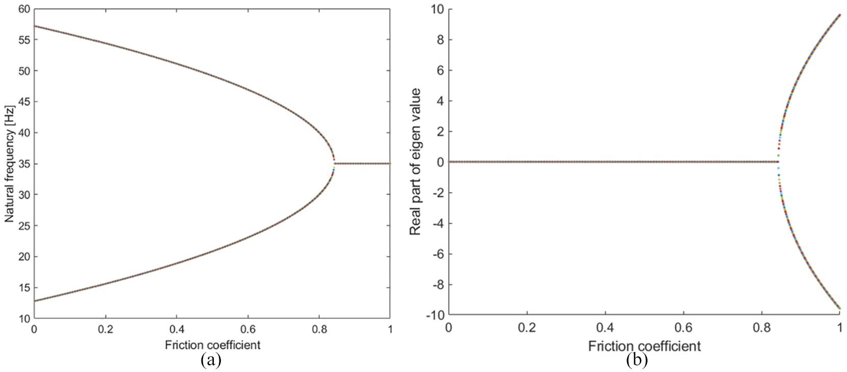
Natural frequencies and real parts of eigenvalues with variation of the friction coefficient: (a) natural frequencies, and (b) real parts of eigenvalues.
Therefore, an efficient technique to prevent the occurrence of squeal noise is to prevent the friction coefficient of the system from becoming negative, to ensure that the dynamic characteristics of the system are not unstable. The negative coefficient of friction in the contact area between the wheel and the rail is closely related to the increase in the creep, and it reaches its maximum limit. Therefore, this study is focused on the use of laser cladding to artificially lower the coefficient of friction at the contact point to ensure that the creep saturation does not occur even if the creep increases; in this manner, the coefficient of friction does not become negative.
Laser cladding is a technology in which two materials are melted and joined using a laser beam. A double metal is introduced on the surface to impart necessary properties such as wear resistance, corrosion resistance, and heat resistance to the base metal surface. Generally, such a surface modification is performed to ensure that the system can withstand the harsh external environment while maintaining the basic properties of the base metal. To coat the material on the rail, welding techniques have often been used.15,16 Furthermore, the rail cladding technology, whose principle is to reduce the friction between the wheels and rails, is known as an effective approach to reduce rail wear.
Consequently, in this study, fusion bonding was performed at the contact interface between the wheel and rail. In addition, the cladding technology was used to reduce the squeal noise in the curved sections by reducing the frictional force at the contact position between the wheel and the rail by using the laser cladding technology. Specifically, the approach involves the application of an alloy powder or mixed powder on the base material by using a bonding material and subsequently using a laser beam. In this work, the welding powder was selecting with the primary objective of reducing the frictional force in contact with the rail. To this end, Hastelloy C was selected as the preferred powder after investigating various powder sources. This material involves a nickel base alloy, and it exhibits a high strength, toughness, oxidation resistance, and fatigue strength in temperatures ranging from cryogenic to 980°C. In addition, Hastelloy C can be used to improve the corrosion resistance against oxidizing materials such as nitric acid and chlorine. The chemical composition and mechanical properties of Hastelloy C are presented in Table 2. 17 The powder is expected to be able to withstand the contact forces generated by a train passing through the curved part after local coating of the rail.
Chemical composition and mechanical properties of Hastelloy C.

Experimental tests with a test rig
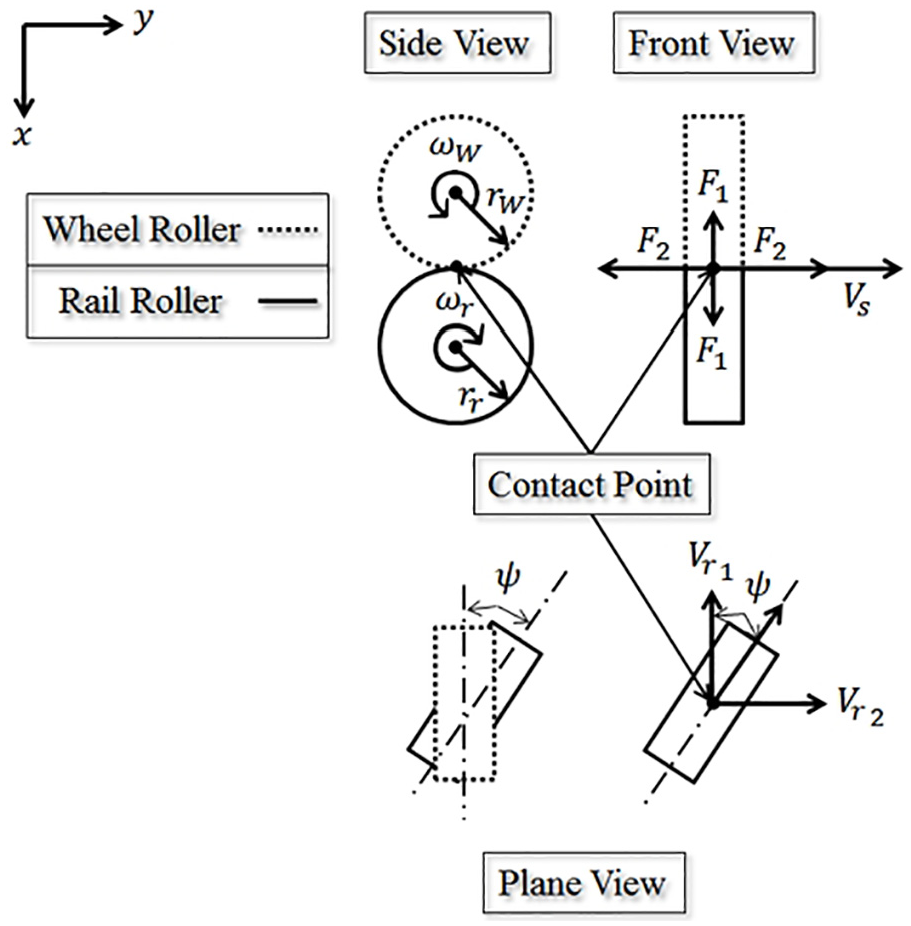
This section describes the determination of the adhesion coefficient of the coating material used to reduce the actual squeal noise. A wheel and rail model tester was analyzed, as shown in Figure 4. The tester consisted of two wheel rollers constrained by one axis and two rail rollers, each driven independently. Because the wheel rollers were manufactured to have the same material properties as those of the actual wheel, the wheel rollers were configured to simulate the movement of the trains traveling on the curved rails as realistically as possible. The rotation speed of the rail roller could be adjusted in units of 1 rpm up to 150 rpm. At this time, the speed was from 0.009 m/s to 1.5 m/s. The yaw angle could be adjusted from −3° to 3° in increments of 0.1°. In addition, the speed of rotation of the left and right rail rollers was controlled using each motor, and the left and right rotations were controlled using the yaw angle motor located in the center of the tester, as shown in Figure 5. Through this control, it was possible to reproduce the situation in which the trains traverse the curved rails.
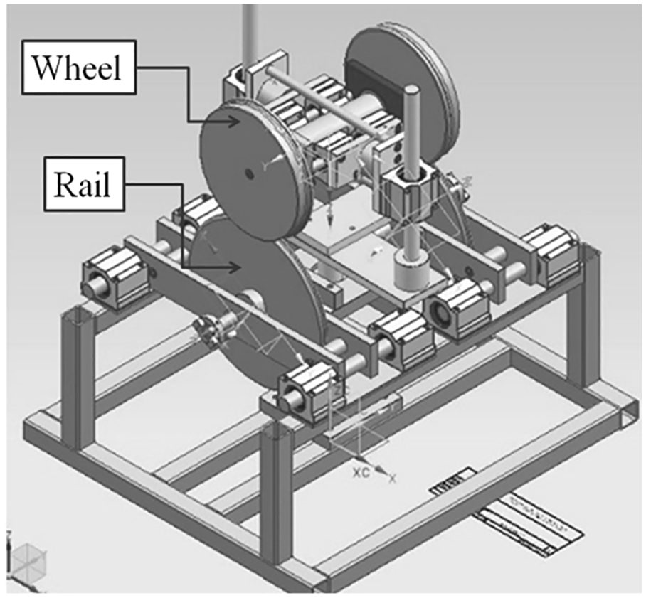
Wheel and rail scale test rig.
Wheel and rail disk with strain gauge to measure the vertical and lateral loads.
The strain gauges were used to measure the coefficient of friction for the lateral creep. The bending of the rail roller caused by the lateral frictional force was measured by using a strain gauge attached to both sides of the rail roller, and the change was converted into digital data through a Wheatstone bridge and an analog digital converter (ADC). In addition, because the rail roller rotates, the data was transmitted wirelessly using Bluetooth communication. In particular, data were obtained from a strain gauge for 60 s with constant rotation of the rail roller at a speed of 50 rpm and by changing the yaw angle in 0.1° increments from 0.0° to a maximum of 2.0°. In addition, the microphones were installed at the left and right points approximately 0.3 m away from the scale tester, and the noise for each yaw angle was measured, as shown in Figure 6.18,19

Data logging equipment with roller rotation.
In the twin-disc model used in this study, the lateral creep between the wheel and rail discs has the following correlation.

where

The adhesion coefficient (

The transverse adhesion coefficient can be obtained by measuring and substituting the lateral creep force against the yaw angle change. A vertical load of 5.5 kg was applied in this study. In addition, the laser cladding process was used to fabricate the rail disc specimens. The laser used for the specimen fabrication was a high-power diode laser (Coherent Highlight 800D, Max: 8 kW). To coat the rails on the test specimens, the surface thickness of the test specimens was reduced by 3 mm, and the composite powder was subjected to laser cladding until a thickness of approximately 3 mm was reached.
In general, the bonding strength of the laser cladding is considerably affected by various factors such as the dilution rate of the base material and the member because to the surface condition, size of the beam, powder supply amount, laser output, and processing speed. The application conditions of the laser cladding used in this study are listed in Table 3.
Laser cladding conditions.

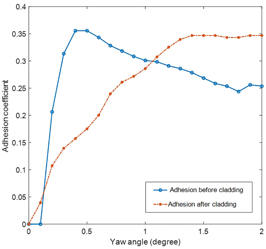
The coefficient of adhesion of the rail disc to the specimen, as determined using the wheel and rail model tester, is shown in Figure 7. In the disk test specimens of the steel materials used in the wheels, the maximum coefficient of adhesion appeared at an angle of approximately 0.4° and gradually decreased with the increase in the angle. This phenomenon corresponds to the case in which the gradient of the lateral creep force becomes negative, and the gradient of the adhesion coefficient becomes negative as the creepage increases. In the period in which the adhesion coefficient becomes negative, the instability of the vibration system may increase, and squeal noise may occur owing to the excessive vibration. However, in the cladding rail disc specimens, the rate of increase of the adhesion coefficient was lower than that of steel as a whole, and its maximum value was higher than that at an angle of approximately 1°. In other words, the adhesion coefficient did not decrease with the increase in the yaw angle. Moreover, when the train is on a steep curve section where squeal noise may be generated, brakes are used to reduce the speed for safety reasons. Therefore, even if the coefficient of friction is low between the wheel and rail when driving on a curve, there is no problem with speed reduction.
Adhesion coefficient of rail specimens.
In addition, noise measurement and analysis were performed for specimens fabricated using the same material and cladding performed with composite materials. Specifically, the vehicle was simulated to travel the curved section with increasing yaw angle. The change in the total noise generation with the change in the yaw angle is shown in Figure 8. In the case of the steel material without cladding, the noise increases sharply at 0.8° when the yaw is increased. In contrast, in the case of the cladded specimen, the increase in the noise occurs more gradually compared to that in the case without cladding.
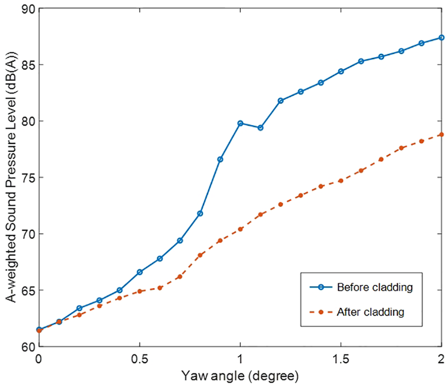
Sound pressure level of the specimens with change in the yaw angle.
In addition, the noise measurement results for yaw angle of 1° and 2° are shown in Figure 9. In the case of steel, a single high-frequency noise of approximately 2000 Hz occurs for both the angles. In particular, when the yaw angle is 2°, the single high single frequency noise occurs not only at 2000 Hz but also at approximately 3000 Hz and 4000 Hz. In contrast, in the case of the composite material, a high noise of a specific frequency does not occur, indicating that the cladding can effectively reduce the squeal noise in the small-scale test equipment.

Sound pressure level of the specimens with change in the yaw angle, in the frequency domain: (a) 1 degree, and (b) 2 degree.
Furthermore, the squeal noise was measured for operational rails in a curved section. The operating urban railway vehicle was selected as the measurement target. The noise was measured with the vehicle reciprocating three times at speeds of 20 km/h and 25 km/h. The data acquisition equipment was a Scada mobile 72 ch by Siemens, and the noise sensor was a 378B02 model PCB. Two microphone sensors were installed at a distance of 0.5 m in the inner and outer region of the curved rail as shown in Figure 10. Squeal noise generation is affected by various conditions such as temperature and humidity, in addition to the physical contact between the wheel and the rail. However, in this study, the region where frequent complaints due to continuous squeal noise were reported was selected as the test site. Our intention was to verify the effectiveness of the proposed method through noise comparison before and after installation. To ensure reproducibility of results, the measurements were made three times and their average was used as the final value.

Measurement site for rail cladding verification.
Noise analysis was performed along with an equivalent noise and frequency analysis. The equivalent noise level was analyzed using the time weighted F (fast) of KS C IEC 61672-1 after calculating the measurement time and the passing time of the railway vehicle based on the measurement position of the train. The measured noise was analyzed considering a narrow band and 1/3 octave band (8–31.5 kHz) to compare the noise before and after the installation of the cladding rail. In addition, the histogram analysis method, which is a curve noise analysis method proposed by TNO, 20 was applied to derive the frequency of the squeal noise by analyzing the distribution of the noise level in units of 1 dB. After the noise measurements were completed before the installation, laser cladding was performed using composites on the surface of the curved rails, centered on the contact with the wheels, as shown in Figure 11. The cladding depth was 2 mm on the rail head and 3 mm on the rail side. The cladding width ranged from 24 to 30 mm on the rail head and 8 to 10 mm on the rail side, taking into account the contact area between the wheel and the rail. The length of the cladding position applied to the contacts was 120 m. The selected rails were welded with powder at the contact point of the wheel and the rail in the curved section, and the rail was installed in the test section.

Laser cladding positions.
The noise reduction effect of the rail cladding was analyzed considering the experimental results. First, the noise reduction results for each speed before and after cladding installation were compared, as shown in Table 4. For a vehicle speed of 20 km/h, the noise generation after the cladding was the same or smaller than that before the cladding. In addition, the noise reduction effect varied depending on the driving direction at the same noise measurement position. This is because the contact position and the attack angle of the wheel and the rail vary depending on the driving direction of the vehicle, even for the same radius of curvature. For the vehicle speed of 25 km/h, the overall noise was increased compared to that at 20 km/h. Furthermore, in the case of the cladded rail, the increase in the noise was not significant at speeds between 20 km/h and 25 km/h. It could thus be confirmed that the noise is significantly reduced compared to that before the installation at the speed of 25 km/h. The cladded rail exhibited a noise reduction of more than 4–9 dB in the vicinity of the rail compared to that before installation at the speed of 25 km/h.
Comparison of average equivalent noise level at the speed of 20 km/h and 25 km/h (dB(A)).

Figure 12 shows the comparison by frequency analysis and indicates that the peak frequencies before the installation of the cladding rail were 2130 Hz, 3170 Hz, 4225 Hz, 5330 Hz, and 6442 Hz at 20 km/h. The results after the installation of the cladding rail confirmed that the noise was reduced in the abovementioned frequency band. At 25 km/h, the peak frequencies before installation of the cladding rails were 2130 Hz, 3170 Hz, 4280 Hz, 5330 Hz, and 6442 Hz. In particular, in the area with the highest noise, the noise level was 101.2 dB around a frequency of 5330 Hz. However, the noise generation in various frequency ranges was significantly reduced after cladding the contact position between wheel and rail. In particular, the noise reduction was remarkably large in the high frequency region of 2000 Hz or more.

Comparison of noise levels before and after cladding the rail, in the frequency domains: (a) sound pressure level at the speed of 20 km/h, and (b) sound pressure level at the speed of 25 km/h.
The cumulative histogram for each occurrence frequency of noise was examined, as shown in Figure 13. In the overall cladding case, the proportion of the high-level noise was reduced. At 20 km/h, noise of 90 dB (A) occupied approximately 85% of the region without cladding. In the case of cladding, this proportion reduced to 50%. At 25 km/h, the noise of 100 dB (A) accounted for 90% of the region without cladding. In the case of cladding, this proportion reduced to 60%. This result indicates that although the noise was reduced, the trend of the noise was not changed. In addition, in the case of cladding, the squeal noise was significantly reduced. In particular, the tendency of the noise could be significantly changed by reducing the noise frequency in the high frequency region. Therefore, in this case, the squeal noise was reduced, thereby also leading to a reduction in the annoyance of the receivers. Since the material applied in this study is in close contact with the rail surface through cladding, it is expected to last for a long time if the effect of wear does not remove it.

Comparative analysis of noise cumulative histogram before and after cladding of the rail.
Conclusion
The reduction in the squeal noise in curved rail sections by using cladding rails was investigated First, the effective reduction measures were considered through a theoretical review of squeal noise. Local coating was performed using a low friction material to prevent the unstable dynamics of the curved part of the system. To this end, a low friction coating powder, namely, the Hastelloy C series powder was used considering its adhesion and durability. The friction coefficient and noise test performed on a small-scaled model indicated that the negative component of the slope of the friction coefficient, which causes the squeal noise, did not appear when the contact surface of the wheel and rail was coated with the powder. Considering the results for the small-scale model, the experiment was performed on an operational curved section track in which squeal noise was generated. The reduction of the squeal noise was examined by comparing the noise generated before and after the installation of the coated rail in the curved section. It was observed that high-frequency squeal noises occurred at a vehicle speed of 25 km/h before the installation of the cladding rail. The noise reduction effect after the installation was examined considering the equivalent noise level, frequency domain noise, and cumulative noise distribution. In terms of the equivalent noise, a noise reduction of more than 4 dB was confirmed, and the frequency domain results indicated a noise reduction of more than 10 dB. These findings demonstrate that the proposed approach can be used to effectively reduce the squeal noise in a semi-permanent manner with low maintenance costs.
Footnotes
Handling Editor: James Baldwin
Declaration of conflicting interests
The author(s) declared no potential conflicts of interest with respect to the research, authorship, and/or publication of this article.
Funding
The author(s) disclosed receipt of the following financial support for the research, authorship, and/or publication of this article: This research was supported by a grant (18TLRP-C146729-01) from Railroad Technology Research Program funded by Ministry of Land, Infrastructure and Transport of Korean government and a grant from R&D Program of the Korea Railroad Research Institute, Republic of Korea.