
Abstract
Nonlinear dynamics behavior of the roller follower is discussed for different follower guides’ internal dimensions and cam angular speeds. A dynamic tool such as Wolf algorithm is used to extract largest Lyapunov exponent parameter. Positive value of Lyapunov exponent parameter indicates non-periodic motion and chaos. The influence of flank curvature of the cam profile on the nonlinear dynamic behavior of the roller follower is investigated. Impulse and momentum theory is used to describe the impact phenomenon based on the contact force between the follower and its guides. Contact parameters such as exponent, sliding contact velocity, contact bodies stiffness, penetration, and damping ratio are used in SolidWorks software to simulate follower movement numerically. Experiment setup has been done by taking into consideration the use of an infrared three-dimensional camera device through a high precision optical sensor. The follower motion is non-periodic when the cross-linking of phase-plane diagram diverges with no limit of spiral cycles.
Introduction
Non-periodic motion could be either quasi-periodic or chaos based on time delay, global embedding dimension, Lyapunov positive, and convergence. The chaos motion of the follower is predicted based on largest positive Lyapunov exponent. Cam-follower system is connected to robotic through a linkage mechanism. The suggested mechanism can be used in bionic quadruped robots to keep the robot walking on a horizontal territory. The detaching phenomenon between the circular cam and the flat-faced follower has been examined by Alzate at distinct cam angular velocities.1,2 A complex nonlinear dynamics behavior such as non-periodic motion could be either quasi-periodic, and chaos for each revolution of the cam. 3 A cam with smooth profile is used to control the impact phenomenon and to prevent follower rebounding. Savi used a small perturbation of a scaler time strides in order to stabilize a desirable orbit of a chaotic attractor.4,5 The abrupt transition from periodic to non-periodic motion is interpreted at high speeds. 6 Moreover, non-periodic motion of the follower has been taken place due to the oscillation motion in drive speed of the cam. 7 A disc cam with a roller follower mechanism is treated as 1- and 2-degree-of-freedom systems to define follower jumping situation at critical angular velocity of the cam. 8 A phase-plane diagram and bifurcation analysis have been used to predict a non-periodic motion and chaos in state space domain. 9 The values of largest Lyapunov parameter are analyzed numerically and experimentally at distinct cam angular speeds and different follower guides’ clearances.10,11 In our previous research, the polydyne cam and roller follower are used (straight line between the nose and the base circle). In this article, the proposed cam has two concave curvatures (flank (1) and flank (2)). The aim of this article is to study the influence of concave curvatures of the cam profile on the nonlinear dynamics behavior for the follower at different follower guides internal dimensions and different cam angular speeds.
Nonlinear dynamic response for the follower
Cam-follower mechanism is treated as a 1-degree-of-freedom system, 12 with mass (m), spring stiffness (k), and viscous damper coefficient (c), as illustrated in Figure 1.

One degree of freedom of follower system.
The follower with simple harmonic motion is assumed since it is widely used and simple to design. It can be assumed that the vibration in cam-follower system is single degree of freedom of simple harmonic motion. The contact load between cam and follower is assumed to be harmonic

where
Divide equation (1) by the mass (m) in which the equation of motion will be

where P is the contact force between cam and follower and is part of F since it comes from dividing F by m;


The homogeneous part of equation (2) will be

Solve the above equation using the solution of quadratic equation for an example
In the particular part of equation (2), it can be assumed that the solution has two parts

where


Substitute


where

where
The symbols
The complimentary solution is as below

Substitute equations (4) and (5) into equation (9) to obtain

The constants
B.C. (1) at
After applying the boundary conditions on equation (10), the constants

Substitute

The dynamic analysis is constructed using the data of follower displacement. With the method of delays from a given data, x(t), a state space, X(t) is reconstructed with the dimension dE: X(i) = [x(i), x(i+T), …, x(i+ (dE− 1)T . In the previous expression, the embedding dimension is
Time delay is an integer number between two samples from time series. If the time series represents a continuous flow with samples taken every

The previous researches suggest that it may be more appropriate to fix the reconstruction window,

The embedding dimension is greater than twice the topological dimension

Largest Lyapunov exponent parameter (

The (

where D is the average displacement between trajectories at t = 0;
Lyapunov exponent is the principal criteria of chaos and represents or decline rate of small perturbation of the phase space system. The increase in expansion degree of the chaotic attractor indicates to largest positive Lyapunov exponent, while the increase in the contraction degree represents to negative Lyapunov exponent. The critical nature of the chaotic attractor means that the value of Lyapunov exponent approaches zero. 16 The mathematical model of largest Lyapunov exponent is as below

where
Numerical simulation
SolidWorks software is used in the numerical simulation to draw a pear cam, roller follower, and the two guides. 18 The dimensions of cam-follower system are shown in Figure 2.

General dimensions of cam-follower system.
There is an internal dimension between the follower and the guide. Cam-follower mechanism with and without spring-damper system at the end of follower stem are considered. Three distinct values of follower guides’ internal dimensions such as 17, 18, and 19 mm are used to simulate the non-periodic motion. The follower is moved with 3 degrees of freedom (up and down, right and left, and rotation about z-axis). The follower guide’s internal dimension and follower degrees of freedom are illustrated in Figure 3.

Follower guide’s internal dimension and the 3 degrees of freedom.
When the follower displacement has been calculated from SolidWorks, Wolf algorithm of dynamic tool is used to calculate largest Lyapunov exponent parameter. The inputs data to Wolf algorithm are one column of follower displacement, time delay, and embedding dimension to calculate largest Lyapunov exponent numerically. The point with the coordinates (x = 0, y = 161.76 mm, z = 0) has been selected in the calculation of follower displacement. The numerical simulation of follower displacement for different cam angular speeds is illustrated in Figure 4(a). Follower displacement is determined analytically using equation (12). Figure 4(b) shows the verification of follower displacement.
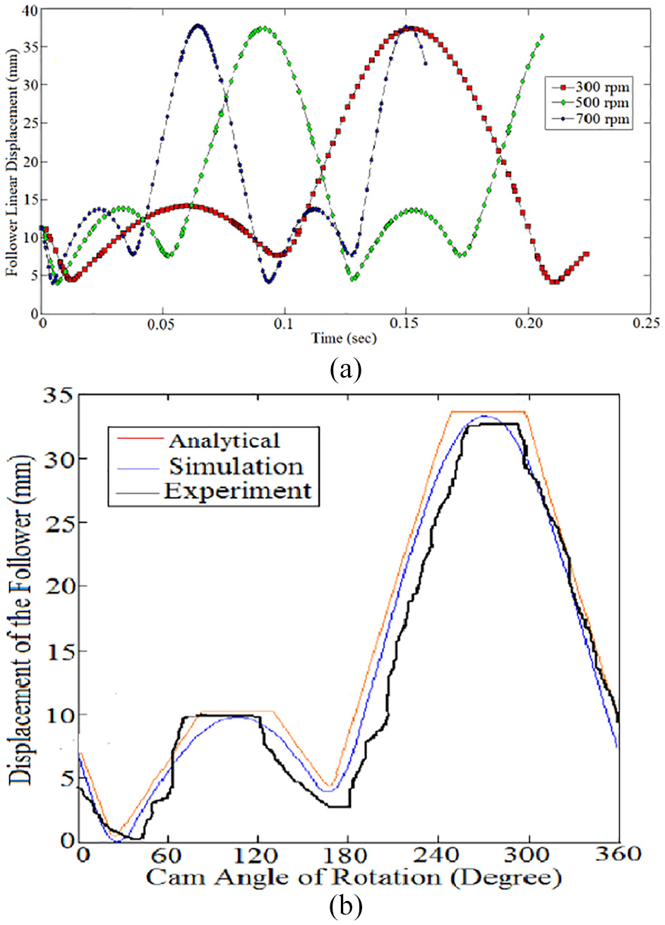
(a) Follower displacement at different cam angular speeds and (b) follower displacement verification versus cam angular speeds.
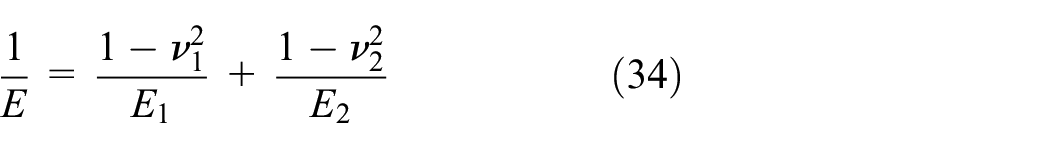
The two concave curvatures (flank 1 and flank 2) are indicated in Figure 5.
Verification of cam profile.
The points of cam profile are obtained by rotating the radius of curvature of roller follower in the opposite direction of the cam rotation.
19
The parameters


where


where
The numerical cam profile has been drawn using SolidWorks software. The analytic cam profile is designed by applying equations (19) and (20) at the point of contact between the cam and the follower.
Contact model of cam-follower system
The spring force is applied at the point with the position x: 0, y: 82.23 mm, z: 0. The spring force is simulated as an external force. The spring force expression function is 13

where a is the preload, b is the spring stiffness,
The contact between the follower stem and the guides is assumed as a contact between two parallel cylinders.
21
The contact model of roller follower and its guides is shown in Figure 6. The dimensions

Contact model of roller follower and its guide.
where

and

From Figure 6, it can be concluded that
where C is the clearance between cam and follower;
As mentioned earlier in the “Numerical simulation” section that the follower has 3 degrees of freedom. The contact between the follower and its guide has been occurred due to the impulse and momentum phenomenon of the follower velocity toward the guide. The follower was going down along y-direction from point (1), and when the follower reached point (2) will start rotating by an angle

where
It can be concluded from the theory of impulse and momentum that the contact force is

The contact force between the follower stem and its guides is as below

where
The contact force between the cam and the follower is calculated from the following formula 13

where
The area of contact will become a rectangular contact zone of half-width

where

where L is the thickness of cam and follower, P is the contact force, and
The depth (

The penetration distance (

where
where
Hertzian contact theory predicts the value of the exponent n based on the flattening law of the shape of the first asperity. The exponent value n is ranging from 1.5 for spherical punch to 2 for wedge shaped punch.
22
The parameters such as the sliding contact velocity (
Experiment setup of dynamic response for the follower
The pear cam and roller follower mechanism are considered in experimental setup. An elastic spring is used to retain the two mechanical parts in permanent contact. Data acquisition technique through signal processing approach is used in the experiment setup. Typically, the follower motion requires a marker in a return loop to assure that the animated object reaches its position. Follower movement is processed experimentally through an infrared three-dimensional (3D) camera device. The incorporated hardware and software scheme of the control unit is used to track the signal of follower movement. The follower position is saved as an excel file. Figure 7 shows the experiment setup of cam-follower test rig.
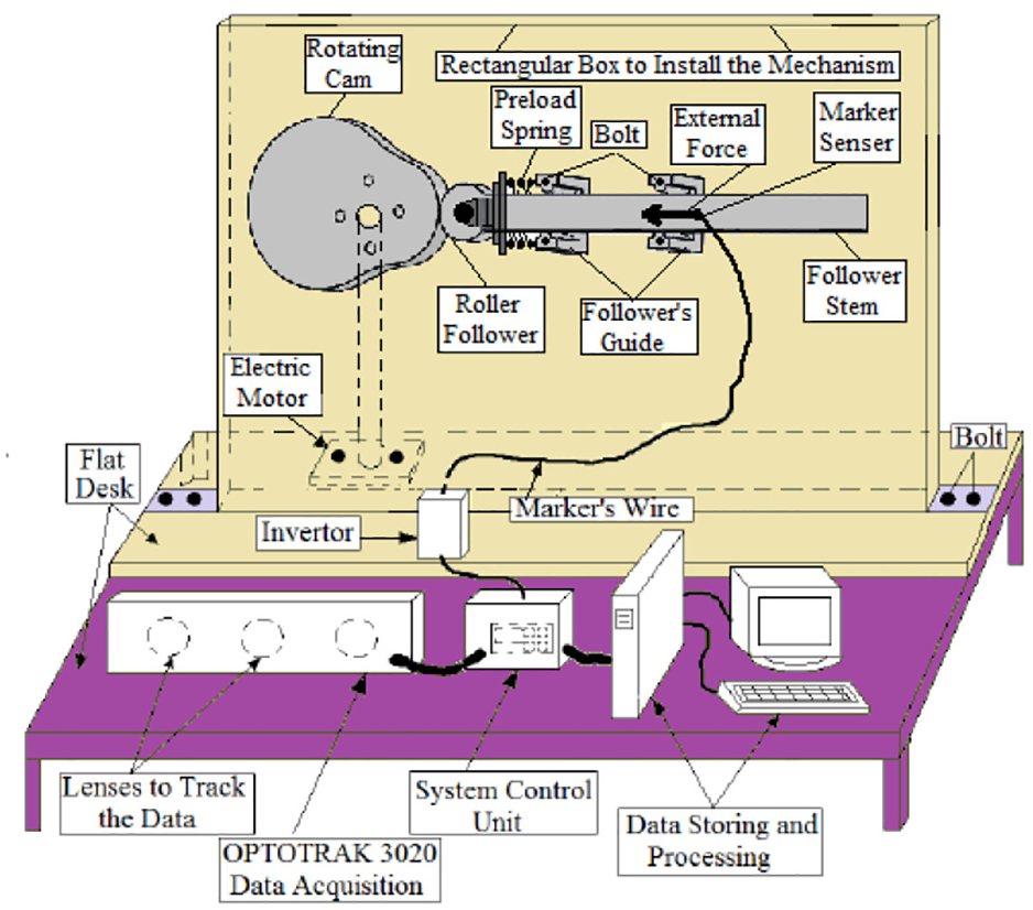
Experiment rig test.
Follower motion verification
The cam profile is drawn based on the consecutive positions of the roller follower around the base circle of a pear cam.
25
A pear cam with a return-dwell-rise-dwell-return-dwell-rise-dwell profile has been selected. The cam starts spinning with a return stroke for

(a) Follower displacement for different motion curves and (b) follower displacement verification for different motion curves.
Figure 9 shows the follower displacement for pear and polydyne cam profiles.

Follower displacement for different cam profiles.
Equations (35a) and (35b) illustrate the displacement of the follower using cycloidal and uniform acceleration and retardation, respectively 25


where y is the theoretical follower displacement, h is the total rise or return,
Nonlinear dynamics behavior
A computer algorithm is used to determine the time delay and the embedding dimension
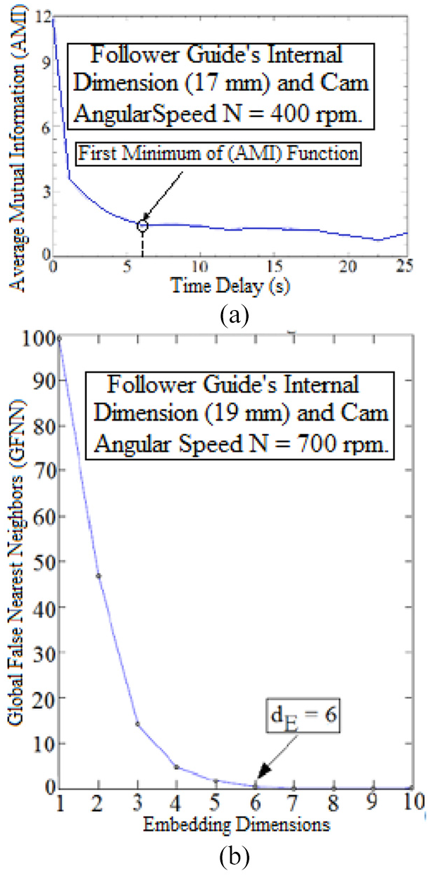
(a) Average Mutual Information versus time delay and (b) global False Nearest Neighbors versus embedding dimensions.
Phase-plane diagram
Phase-plane diagram represents how the small variation in follower displacement grows or shrinks over the time. When the orbit of phase-plane diagram is one spiral which means that the follower motion is periodic (negative Lyapunov exponent). The follower motion is non-periodic when the orbit of phase-plane diagram diverges with no limit of spiral cycle (positive Lyapunov exponent). Negative Lyapunov exponent indicates convergence, while positive Lyapunov exponent demonstrates divergence and chaos. 11 As mentioned earlier in the “Numerical simulation” section that the spring-damper system is used to decrease the variation in follower motion. In our previous research, the polydyne cam and roller follower are used (straight line between the nose and the base circle). In this article, the pear cam and roller follower are used (flank (1) and flank (2) between the nose and the base circle). Figures 11 and 12 show the verification of phase-plane diagram for follower guide’s internal dimension (19 mm) at N = 1000 rpm.
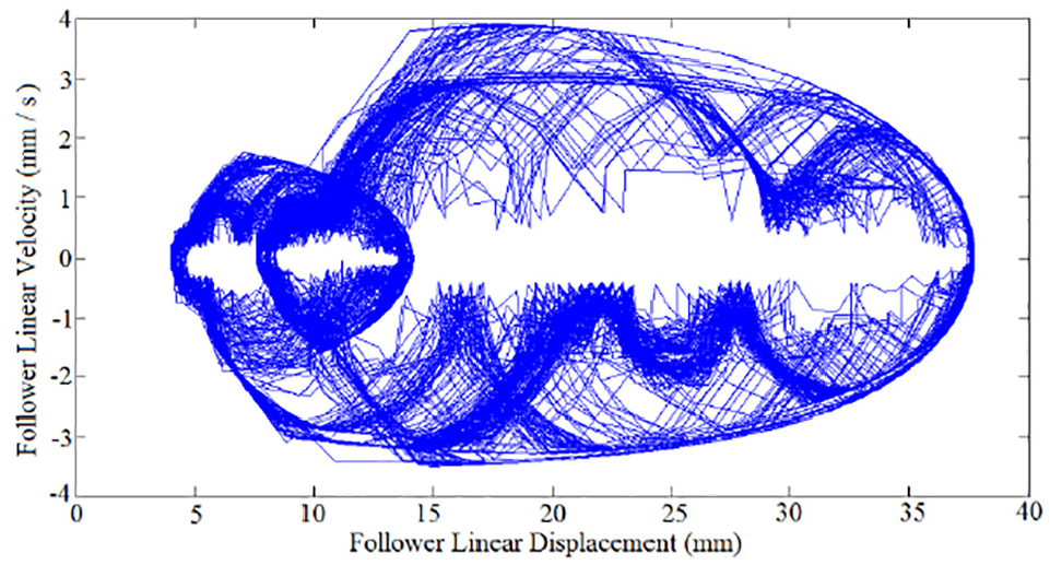
Phase-plane diagram of numerical simulation.
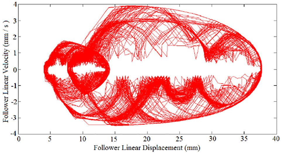
Phase-plane diagram of experiment setup.
Lyapunov exponent and power spectrum analysis
Wolf algorithm is used to calculate largest Lyapunov exponent. The inputs data for the wolf algorithm are time delay, embedding dimensions, and the follower’s position in the y-direction. Lyapunov exponent is estimated from the best-fit linear slope of average logarithmic divergence over the time between 4 and 10 cycles. Largest Lyapunov exponent has been selected to predict follower non-periodic motion. Figure 13 shows the average logarithmic divergence of largest Lyapunov exponent parameter at different cam angular speeds.

Average logarithmic divergence of largest Lyapunov exponent at follower guide’s internal dimension (17 mm) at N = 300 and 500 rpm.
The fast Fourier transform (FFT) algorithm is carried out by converting the signal of follower displacement from its original domain to the frequency domain. Non-periodicity has been occurred due to follower motion with 3 degrees of freedom, follower guide’s internal dimension, and flank curvatures of pear cam profile (flank (1) and flank (2)). 26 Figures 14 and 15 show the verification of power spectrum for follower guide’s internal dimension (19 mm) using FFT.

Power spectrum analysis of numerical simulation.

Power spectrum analysis of experiment setup.
Results and discussions
Figures 16 and 17 show the average logarithmic divergence of Lyapunov exponent varying with different follower guides’ internal dimension and cam angular speeds. The nonlinear curve represents the average logarithmic divergence of the follower motion. The straight line represents the slope of average logarithmic divergence which reflects the value of largest Lyapunov parameter. The systems with follower guides’ internal dimension (18 and 19 mm) at cam angular speed N = 500 rpm in which it gives the perfect best-fit of linear slope to quantify largest value of largest Lyapunov exponent. The nonlinear curve of average logarithmic divergence when follower guide’s internal dimension (18 and 19 mm) at N = 300 rpm has been fluctuated around the linear slop of curve fitting.

Average logarithmic divergence for follower guide’s internal dimension (19 mm).

Average logarithmic divergence for follower guide’s internal dimension (18 mm).
Figures 18 show the mapping of power spectrum analysis of FFT for different follower guides’ internal dimensions (17 and 19 mm) and different cam angular speeds. Six peaks of frequency have been appeared in the analysis of power spectrum in which the first frequency represents the fundamental frequency. The frequencies’ peaks are clear and close to each other in which it represents the periodic and quasi-periodic motion for the follower as indicated in Figure 18(a) and (b) at N = 400 rpm and N = 600 rpm, respectively. The frequencies’ peaks are disappeared gradually with the increasing of cam angular velocity and follower guide’s internal dimension. Figure 18(d) shows the non-periodic motion and chaos of the follower motion because the six frequencies’ peaks are disappeared completely at N = 1000 rpm.

Mapping of power spectrum analysis of pear cam profile: (a) follower guide’s internal dimension (17 mm) at N = 400 rpm; (b) follower guide’s internal dimension (17 mm) at N = 600 rpm; (c) follower guide’s internal dimension (19 mm) at N = 800 rpm; and (d) follower guide’s internal dimension (19 mm) at N = 1000 rpm.
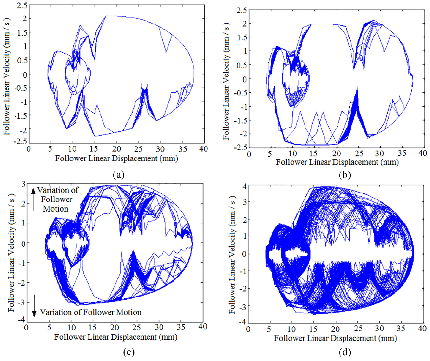
Figure 19 shows the mapping of phase-plane diagram of follower guides’ internal dimensions (17, 18, and 19 mm) at distinct cam angular velocities. The variation of follower motion (the cross-linking) is increased with the increasing of follower guides’ internal dimensions and cam angular velocities without using spring-damper system. The follower motion is non-periodic when the orbit of phase-plane diagram diverges with no limit of spiral cycles, as indicated in Figure 19(d).

Mapping of phase-plane diagram of pear cam profile without using spring-damper system: (a) follower guide’s internal dimension (17 mm) at N = 400 rpm; (b) follower guide’s internal dimension (18 mm) at N = 600 rpm; (c) follower guide’s internal dimension (18 mm) at N = 800 rpm; and (d) follower guide’s internal dimension (19 mm) at N = 1000 rpm.
Figure 20 shows the mapping of phase-plane diagram of follower guides’ internal dimensions (17, 18, and 19 mm) at distinct cam angular velocities for pear cam profile. Figure 21 shows the mapping of phase-plane diagram for polydyne cam profile. The variation of follower displacement grows in double cycle of motion as shown in Figure 20(a) and (b), while the follower motion is varied in multiple orbits over the time as indicated in Figure 20(c) and (d). The cross-linking of phase-plane diagram is decreased when spring-damper system has been used. The follower motion is non-periodic when the orbit of phase-plane diagram diverges with no limit of spiral cycles. The variation of follower displacement using pear cam and roller follower is bigger than the variation of follower displacement using polydyne cam and roller follower. The cross-linking of follower displacement without using spring-damper system is bigger than the cross-linking of follower displacement using spring-damper system, as shown in Figures 19(d) and 20(d).
Mapping of phase-plane diagram of pear cam profile using spring-damper system: (a) follower guide’s internal dimension (17 mm) at N = 400 rpm; (b) follower guide’s internal dimension (18 mm) at N = 600 rpm; (c) follower guide’s internal dimension (18 mm) at N = 800 rpm; and (d) follower guide’s internal dimension (19 mm) at N = 1000 rpm.
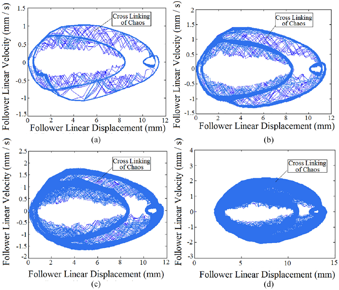
Mapping of phase-plane diagram of polydyne cam profile 11 : (a) follower guide’s internal dimension (17 mm) at N = 400 rpm; (b) follower guide’s internal dimension (18 mm) at N = 600 rpm; (c) follower guide’s internal dimension (18 mm) at N = 800 rpm; and (d) follower guide’s internal dimension (19 mm) at N = 1000 rpm.
Conclusion
In this study, the effect of pear cam and polydyne cam profiles on the nonlinear dynamics behavior is checked and verified using phase-plane diagram and power spectrum analysis. The orbits of phase-plane diagram for pear and polydyne cam profiles are increased with increasing of follower guide’s internal dimension and cam angular speeds. A spring-damper system is used to decrease the variation in follower motion since it reduces the nonlinear dynamics behavior of the follower. The cross-linking of follower displacement without using spring-damper system is bigger than the cross-linking of follower displacement using spring-damper system for pear cam. In general, all the values of largest Lyapunov exponent parameter are positive so that gives an idea to non-periodic motion and chaos. Largest Lyapunov exponent parameter is increased with increasing of follower guide’s internal dimension and cam angular velocity.
Recommendation of the future work
The recommendation of the future work is as below: (1) study the effect of follower eccentricity on the non-periodic motion and chaos based on Lyapunov parameter. (2) Improve the non-periodic motion and chaos by reducing Lyapunov parameter using genetic algorithm technique.
Footnotes
Appendix
Acknowledgements
The authors want to first thank the reviewers and the editor for reviewing the article.
Handling Editor: James Baldwin
Declaration of conflicting interests
The author(s) declared no potential conflicts of interest with respect to the research, authorship, and/or publication of this article.
Funding
The author(s) received no financial support for the research, authorship, and/or publication of this article.