
Abstract
Rotary ultrasonic machining has been approved as an effective and efficient hole making process for carbon fiber–reinforced plastic composites. Hole quality plays an important role in assembling carbon fiber–reinforced plastic components and can be affected by the carbon fiber reinforcement structures. In this study, experiments are conducted to assess hole quality in carbon fiber–reinforced plastic composites with three carbon fiber reinforcement structures under different combinations of machining variables. Hole quality is quantified through geometrical accuracy (perpendicularity, cylindricity, and hole diameter) and surface qualities (delamination and surface roughness). Results show that the highest level of interlacement among yarn of plain woven structure induce the highest level of compression to the workpiece and the largest amount of additional material removal, leading to the largest perpendicularity and hole diameter. The worst fabric integrity of unidirectional structure generates the largest amount of non-uniform material removal on the machined surface, resulting in the largest cylindricity. It is also found that compared with woven structures, unidirectional structure is more likely to induce push-out delamination due to its smaller critical energy release rate. The lowest constancy of the fabric in twill woven structure leads to the largest surface roughness.
Keywords
Introduction
Carbon fiber–reinforced plastic (CFRP) composites, characterized by lightweight and high strength-to-weight ratio, are comprised of carbon fibers and epoxy resin. The high-strength carbons fibers are used to support the load, while the epoxy resin matrix is used to transfer the load to the carbon fibers. The combination of carbon fiber and epoxy resin also makes CFRP composites have the advantages of good dimensional stability, good thermal stability, high stiffness, high damping capacity, good corrosion resistance, and high wear resistance.1,2 Owing to these superior properties, CFRP composites are increasingly used in automobile, aerospace, civil engineering, and sports goods industries in recent years. 3 In the applications for assembly purposes, CFRP composites are usually joined with other structures by mechanical fastening methods, such as riveting and bolting. Therefore, hole making of CFRP composites is an indispensable machining process.4–6 However, CFRP composites are considered as hard-to-machine materials due to structural anisotropic properties, lack of plastic deformation, and high abrasiveness of carbon fibers.1,7 Conventional hole-making methods, such as twist drilling (including its derived methods), milling, and grinding, induce common issues of high cutting force, poor hole quality, severe tool wear, and so on.8–11 Several non-traditional machining processes, such as helical milling, tilted helical milling, wobble milling, and rotary ultrasonic machining (RUM), have been proposed in hole making of CFRP composites to reduce or eliminate these issues.12–15 The helical milling and tilted helical milling, utilizing an end mill tool and exhibiting planetary motion around the hole axis, could reduce cutting temperature, improve hole quality, and improve processing efficiency. 13 Wobble milling could reduce cutting force and delamination by tilting the mill tool in the machining process. 14 RUM, which combined the grinding hole making process with ultrasonic vibration assistance, was effective and efficient in machining CFRP composites in high quality when comparing with twist drilling and grinding.16,17 Therefore, RUM was widely investigated. In RUM, the workpiece material was removed by the abrasive grinding of the cutting tool with the assistance of ultrasonic vibration. Figure 1 illustrates the schematic of RUM. During machining, a rotating diamond core drill was feeding toward the workpiece and ultrasonically vibrating vertically under a set frequency simultaneously. The coolant was pumped through the diamond core drill bit to the interface of the workpiece and cutting tool. In this way, the cutting chips could be washed away and the temperature at the interface could be reduced.
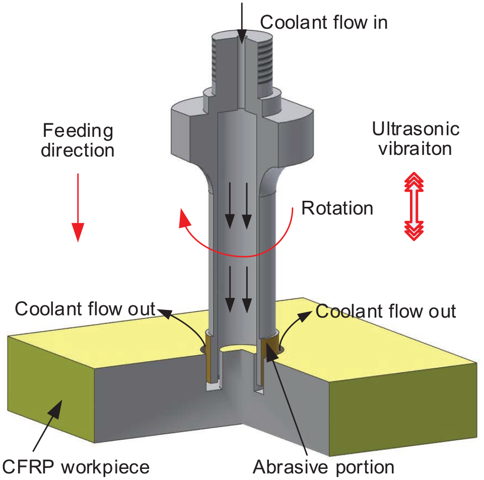
The schematic of rotary ultrasonic machining (RUM).
In RUM hole making of CFRP composites, many experimental and theoretical investigations have been conducted on the effects of machining variables (including tool rotation speed, feedrate, and ultrasonic power), cooling medium (cutting fluid or cold air), and tool variables (tool geometry, tool diameter, abrasive concentration, abrasive size) on some output variables (including cutting force, torque, cutting temperature, delamination, burning of machined surface, surface roughness, and tool wear) are reported.15,18–28 Generally speaking, the increase of tool rotation speed, decrease of feedrate, and the increase of ultrasonic power could reduce cutting force, torque, and delamination. Existing investigations mainly focused on machining performance in the RUM process. Hole quality will affect the stability, reliability, and durability of the final assembly. Therefore, it plays an important role in assembling CFRP components.4,29–32 However, there are no comprehensive studies on quantifying hole quality in RUM hole making of CFRP composites. This study aims to fill such research gaps and quantify the hole quality of CFRP composites in RUM from different workpiece and process perspectives.
In this study, the effects of machining variables and carbon fiber reinforcement structure on geometrical accuracy (perpendicularity, cylindricity, and hole diameter) and surface qualities (delamination and surface roughness) were investigated. After this section, the experimental setup will be introduced. The carbon fiber reinforcement structures and machining variables will also be discussed. The results and discussion and the conclusion will be presented in the last two sections, respectively.
Workpiece materials, experimental setup, and measurement procedures
Workpiece structures and properties
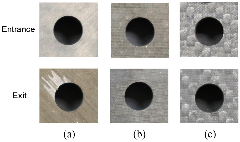
As shown in Figure 2, the CFRP composites used in this investigation had three different kinds of carbon fiber reinforcement structures. Figure 2(a) represents unidirectional structure, Figure 2(b) represents plain woven structure, and Figure 2(c) represents Twill woven structure. In the unidirectional structure, the carbon fibers in a certain layer had one direction. However, different layers had different fiber orientations. In woven structures, carbon fibers were fabricated into yarn. Yarn formed a crisscross pattern in the plain woven structure and a diagonal pattern in the twill woven structure.33,34 Table 1 lists detailed workpiece properties.

The illustration on the three carbon fiber reinforcement structures: (a) unidirectional structure, (b) plain woven structure, and (c) twill woven structure.
Workpiece material properties.

HRB: Rockwell hardness.
Experimental setup and conditions
As illustrated in Figure 3, a rotary ultrasonic machine (Series 10; Sonic-Mill, Albuquerque, NM, USA) was used to conduct the hole making experiments. The experimental setup was mainly comprised of an ultrasonic spindle system and a coolant system. There were four major components in the ultrasonic spindle system: a control panel, an ultrasonic power supply, an electric motor, and an ultrasonic spindle. The control panel was used to set the machining variables, such as tool rotation speed, feedrate, ultrasonic power, and so on. The ultrasonic power supply could convert the electrical energy from low frequency (60 Hz) to high frequency (20 kHz), which was then converted to high-frequency mechanical vibration. The mechanical vibration was finally transmitted to the diamond core drill bit through the ultrasonic spindle. The electric motor, which was located on the top of the ultrasonic spindle, was used to provide a set rotation speed to the diamond core drill bit. The coolant system, which was consisted of a pump, a pressure regulator, a coolant tank, two valves, and so on, was used to pump the oil-based coolant (Quakercool 6010 ND; Quaker Chemical Corporation, Conshohocken, PA, USA) through the diamond core drill bit. In this way, the temperature at the contact region of the cutting tool and the workpiece could be reduced and the machined cutting chips could be washed away.
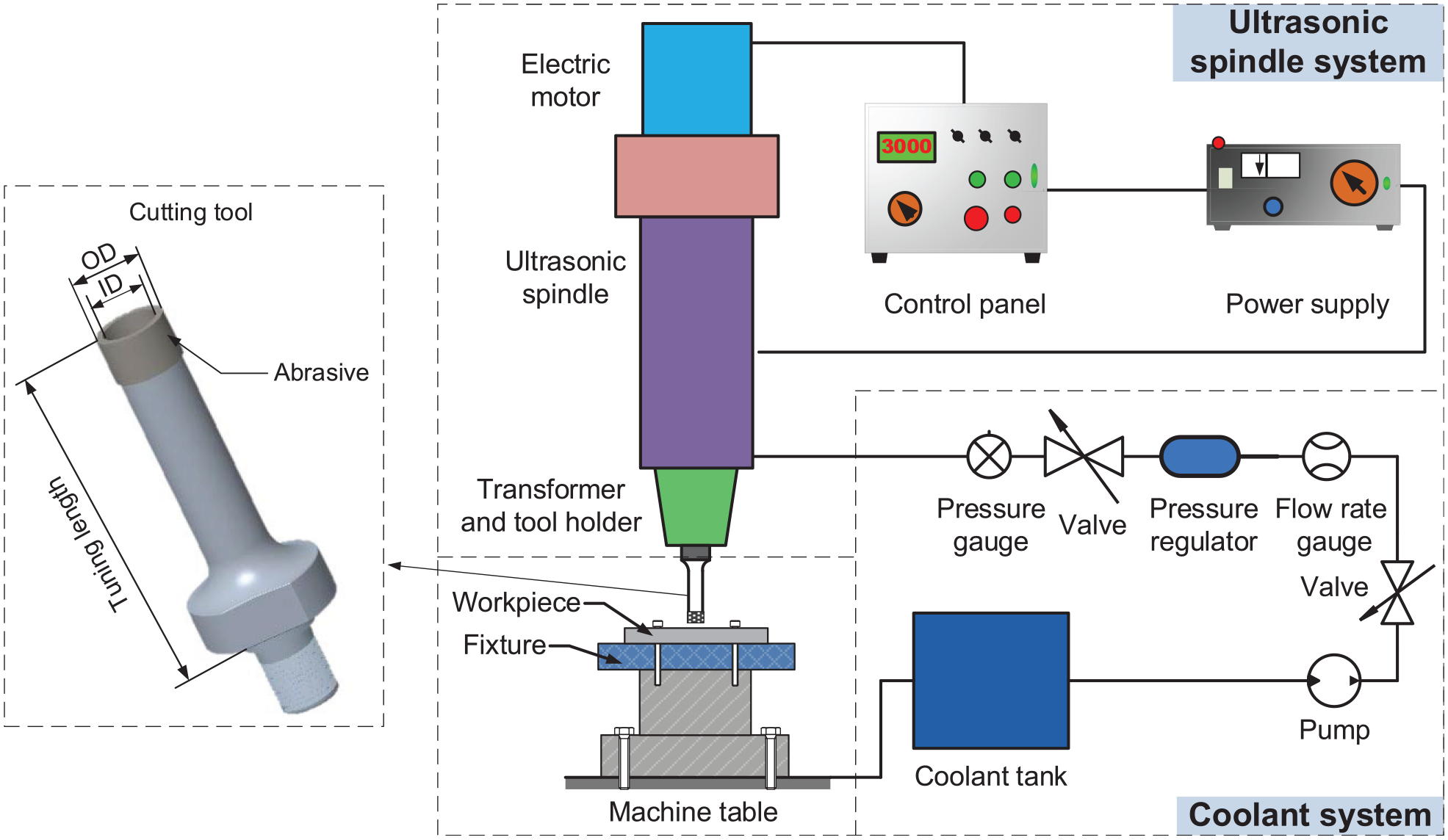
RUM experimental setup.
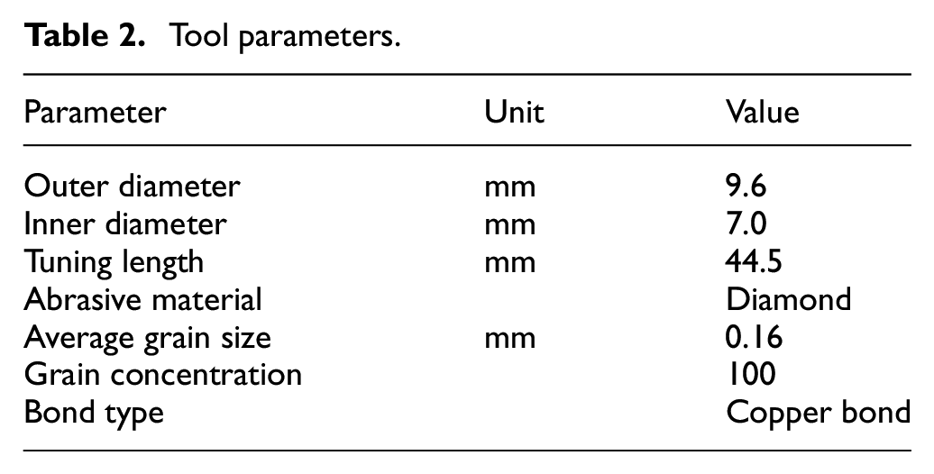
Figure 3 shows the diamond core drill bit (NBR Diamond Tool Corp., LaGrangeville, NY, USA) used in this investigation. Table 2 lists the detailed parameters of the tool. Table 3 shows experimental conditions and lists the values of the machining variables (including tool rotation speed, feedrate, and ultrasonic power) of each group. The selection of these values was based on previously reported investigations and preliminary experiments. Each experiment under a certain combination of machining variables was conducted 3 times. The experiments were conducted following the sequence as shown in Table 3.
Tool parameters.
Experimental design table.

Duplicated experiments were not reconducted.
Measurement procedures
A coordinate measuring machine (CMM; Crysta-Apex S 544, Mitutoyo American Corporation, Aurora, IL, USA) was used to measure the profiles of the holes. The schematic of hole profile CMM testing is illustrated in Figure 4. A probe with a diameter of 4 mm was used in the measurement. The hole profile was measured by probing a total number of 40 points at five axial positions along the hole. The distances of the axial positions from the hole entrance were 2.5, 4.5, 6.5, 8.5, and 10.5 mm, respectively. Perpendicularity, cylindricity, and hole diameter were measured and analyzed by the CMM built-in software (MCOSMOS v4.2; Mitutoyo American Corporation). The perpendicularity of a hole defines the straightness of the center axis of the hole with respect to a datum plane. Figure 5 shows the illustration of perpendicularity. Several points selected from the top surface of the CFRP composites were used to define the datum. The value of the perpendicularity was the diameter of the tolerance zone (Dtz) in which the central axis of the measured hole lay. The cylindricity controls the overall form of a cylindrical feature. As illustrated in Figure 6, the difference between the radius of the circumscribed cylinder (rc) and the radius of the inscribed cylinder (ri) was the value of the cylindricity. Three measurements were conducted for each hole profile.
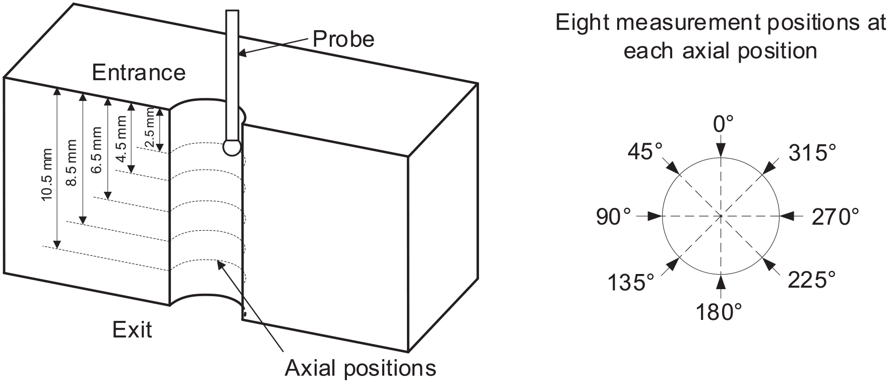
Measurement of hole profile.

Illustration of perpendicularity.
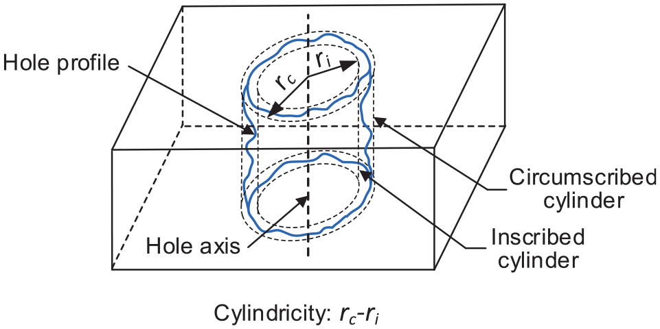
Illustration of cylindricity.
Delamination, the interlaminar crack propagation of fiber-reinforced composite laminates, was the most critical failure mode in hole making of composite laminates.3,35 As illustrated in Figure 7, delamination could be categorized as peel-up delamination occurring at the hole entrance and push-out delamination which occurred at the hole exit. The entrance side of each machined holes were examined to check whether there was any peel-up delamination. As shown in Figure 8, the ratio of the maximum diameter of the delamination area (Dmax) to the nominal diameter of a machined hole (Dnom) was defined as the delamination factor. The CMM was used to measure the maximum diameter of the delamination area (Dmax).

Illustration of peel-up delamination and push-out delamination.

Illustration of delamination factor.
A surface profilometer (Surftest-402; Mitutoyo Corporation, Kanagawa, Japan) was used to measure the surface roughness (Ra) on the machined cylinder surface of the holes. Four positions at the outline of the holes were selected for the measurement. At each position at the outline, three measurements were conducted along the axial direction with the cut-off length of 0.8 mm and the total measuring range of 4 mm. The average value from all measurements was used to express surface roughness. A scanning electron microscope (SEM—Phenom; Nanoscience Instruments, Phoenix, AZ, USA) was used to take the images on the surfaces of the CFRP composites.
Experimental results and discussion
Figures 9–15 show the perpendicularity, cylindricity, hole diameter, delamination, and surface roughness of the machined holes on the CFRP workpieces with different carbon fiber reinforcement structures under different machining variables, respectively.

Effects on perpendicularity: (a) Effects of tool rotation speed, (b) Effects of feedrate and (c) Effects of ultrasonic power.

Effects on cylindricity: (a) Effects of tool rotation speed, (b) Effects of feedrate and (c) Effects of ultrasonic power.

Effects on hole diameter: (a) Effects of tool rotation speed, (b) Effects of feedrate and (c) Effects of ultrasonic power.
The comparison of delamination of CFRP composites with different carbon fiber reinforcement structures: (a) unidirectional, (b) plain woven, and (c) twill woven.

Effects of machining variables on push-out delamination factor of CFRP composites with unidirectional structure.

Effects on average surface roughness: (a) Effects of tool rotation speed, (b) Effects of feedrate and (c) Effects of ultrasonic power.

Observations of the machined holes using SEM: (a1) and (a2) Unidirectional structure; (b1) and (b2) Plain woven structure; and (c1) and (c2) Twill woven structure.
Effects on perpendicularity
Figure 9 shows the experimental results of perpendicularity. In machining of the CFRP workpiece with twill woven and unidirectional structures, the perpendicularity increased when ultrasonic power decreased, tool rotation speed increased, or feedrate increased. However, opposite trends were observed when machining the CFRP workpiece with the plain woven structure. Twill woven structure and unidirectional structures had worse fabric integrity and lower level of interlacement among yarn compared with plain woven structure. Therefore, these two structures had a higher level of anisotropy. During the machining process, the cutting tool would deflect to weaker areas due to the anisotropy of the material. Cutting tool deflection induced by material anisotropy was probably the primary influencing factor on the perpendicularity in twill woven and unidirectional structures. When the ultrasonic power decreased or the feedrate increased, the cutting force would increase accordingly.22,36,37 Thus the compression between the cutting tool and the workpiece would also increase. The increased tool rotation speed led to the increase of effective cutting time, which was defined as the time period during which the abrasive grains of the diamond core drill bit penetrated into the workpiece. 38 The increased effective cutting time would induce higher thermal distortions on the machined cylinder surface of the holes. Increased compression on the workpiece and higher thermal distortions would make the cutting tool deflection induced by material anisotropy severer, which made the perpendicularity larger. Similar phenomena and explanations were reported in twist drilling of fiber–metal laminates by Giasin. 39 The plain woven structure had less anisotropy than unidirectional and twill woven structures. The effects of machining variables on cutting tool deflection induced by material anisotropy could be ignored. Instead, the elastic deformation of the cutting tool during machining could be the primary influencing factor. With ultrasonic power decreasing, or feedrate increasing, the effective cutting time per unit area decreased. Less elastic deformation on the cutting tool surface was generated, accordingly. The increase of tool rotation speed would induce decreased uncut chip thickness, which could induce a lower level of elastic deformation of the cutting tool.
Figure 9 also shows that the largest perpendicularity was induced on the CFRP workpiece with plain woven structure. The CFRP workpieces with twill woven and unidirectional structures exhibited similar hole perpendicularity values, which were smaller than the values obtained from the CFRP workpiece with plain woven structure. Compared with twill woven and unidirectional structures, the plain woven structure had the highest level of interlacement among yarn, which made the cutting tool generated the highest level of compression to the workpiece. With this case, the severest elastic deformation of the cutting tool was generated when machining the CFRP workpiece with plain woven structure.
Effects on cylindricity
The effects of machining variables and carbon fiber reinforcement structure on cylindricity are shown in Figure 10. The cylindricity increased when ultrasonic power increased, tool rotation speed increased, or feedrate decreased. The cylindricity could be affected by the difference between the hole entrance size and hole exit size. In RUM, the diamond core drill bit stayed a longer time near the hole entrance than at the hole exit. With this case, more materials were removed near the hole entrance, which induced a larger hole diameter at the hole entrance than that at the hole exit. The increased ultrasonic power, decreased feedrate, or increased tool rotation speed generated longer effective cutting time per unit area. The difference in machining time between the entrance area and exit area of the hole increased accordingly, which further increased the difference between the hole diameter at the entrance and that at the exit.
It also can be seen from Figure 10 that the unidirectional structure led to the largest hole cylindricity, followed by the two woven structures. The cylindricity values of the two woven structures were similar. Compared with the two woven structures, the unidirectional structure had a higher level of the anisotropic property. Therefore, radial forces with the largest fluctuant range were induced, which led to the highest level of tool oscillation, reflection, and wandering. 40 These factors led to the largest amount of non-uniform material removed on the machined surface. The combination of the largest amount of non-uniform material removal and longer machining time at hole entrance would further increase the difference in the size between hole entrance and hole exit. In addition, the unidirectional structure had the worst fabric integrity compared with woven structures. Another possible reason for its largest cylindricity in unidirectional structure was the most uncut, deflected, or stretched out carbon fibers on the hole surface during machining.
Effects on hole diameter
Figure 11 compares the hole diameter of the CFRP workpieces with different carbon fiber reinforcement structures under different combinations of machining variables. With the decrease of ultrasonic power, the hole diameter decreased in the CFRP workpiece with the plain woven structure. However, the hole diameter in CFRP composites with the other two structures had little changes. With the increase of the tool rotation speed or the decrease of the feedrate, the hole diameter of all machined CFRP composites increased. The increase of ultrasonic power would affect overlapping of abrasive grains of the hole surface. The increase of tool rotation speed, or the decrease of feedrate would generate larger effective cutting time per unit area. More material was removed on the hole surface, accordingly. Unidirectional and twill woven structures had fewer interlacements among yarn, which could make CFRP composites with these structures had less sensitivity to ultrasonic vibration of the cutting tool.
Figure 11 also shows that the CFRP workpiece with the plain woven structure had the largest hole diameter, followed by the CFRP workpiece with the twill woven and unidirectional structures. The plain woven structure had the best fabric integrity and the most interlacements among yarn.29,41 The major reason for the largest hole diameter in the plain woven structure was that the largest amount of additional material on the sub-machined surface was removed. In contrast, the unidirectional structure had the worst fabric integrity and the least interlacement among yarn, which induced the smallest hole diameter. Similar phenomena could be found in twist drilling of CFRP workpieces with plain woven and unidirectional structures. 42
Effects on delamination
Figure 12 compares the delamination of CFRP workpieces with different carbon fiber reinforcement structures. All the CFRP composites did not show observable peel-up delamination. The CFRP workpieces with the unidirectional structure had remarkable push-out delamination. In contrast, the CFRP workpiece with the plain woven and twill woven structures did not show observable push-out delamination. The peel-up delamination, usually observed from the entrance side of the CFRP composites drilled by twist drilling, mainly resulted from the peeling force through the slope of the drill bit flutes. The major reason for no observable peel-up delamination in RUM of all the CFRP workpieces is that the diamond core drill bit would exert little peeling force to the surface near the entrance of the hole.8,43 In addition, the materials were removed by the indentation of the cutting tool in RUM. The initiation of the push-out delamination was correlated to the critical energy release rate, which was a measure of the energy necessary for crack initiation. 44 The remarkable push-out delamination in CFRP composites with unidirectional structure resulted from its much smaller critical energy release rate than the two woven structures. In addition, the push-out delamination was more likely to happen than peel-up delamination since the uncut plies beneath the cutting tool were more likely to deform with the decrease of the thickness of the uncut plies.7,45 Similar results and explanations were reported in tensile tests of CFRP composites. 46
The CFRP composites with the two woven structures (plain woven and twill woven structures) did not exhibit observable delamination after machining at different levels of machining variables. Figure 13 shows the delamination factors at the exit of the holes when machining CFRP workpiece with unidirectional structure under different combinations of machining variables. The delamination factor increased when the ultrasonic power decreased, tool rotation speed decreased, or feedrate increased. It was reported that the increased cutting force under these changes of machining variables was the major reason to generate the severer delamination.31,47
Effects on surface roughness
Figure 14 shows the changes of surface roughness under different machining variables and carbon fiber reinforcement structures. Surface roughness decreased when ultrasonic power increased, tool rotation speed increased, feedrate decreased. The major reason was that with these changes in machining variables, the effective cutting time per unit area increased. Thus, more convex or uncut materials on the hole surface were removed.
Figure 14 also shows that the largest surface roughness was observed on the CFRP workpiece with the twill woven structure. It was reported that the twill woven structure had the lowest yarn density with the largest gaps between the yarn in the fabric structure.33,48–50 Compared with the other two structures, the constancy of the fabric in twill woven structure was the lowest, which led to the most voids on the machined surface. In addition, the largest portion of voids in the machined surface could also be generated by the way the carbon fibers were cut in twill woven structure. The SEM images of the machined hole surfaces are shown in Figure 15. The enlarged view of the fracture regions of the carbon fibers shows that the carbon fibers in twill woven structure were cut in bunches due to its diagonal pattern of the yarn. In contrast, SEM images did not show such phenomenon on the machined surface of unidirectional and plain woven structures.
Lacks and possible future works
This work mainly focused on the experimental studies of the hole quality issues in RUM hole making of CFRP composites. There was a lack of theoretical investigation on the hole quality of CFRP composites with different carbon fiber reinforcement structures under different machining parameters. Therefore, possible future work would be developing a theoretical model or statistical model to predict the hole quality in RUM hole making of CFRP composites.
Conclusion
In this article, the effects of carbon fiber reinforcement structure and machining variables (including tool rotation speed, feedrate, and ultrasonic power) on hole quality (including perpendicularity, cylindricity, hole diameter, delamination, and surface roughness) in RUM hole making of CFRP composites were investigated. The major conclusions are listed as follows:
For CFRP composites with unidirectional and twill woven structures, the increased ultrasonic power resulted in decreased perpendicularity, increased cylindricity, and increased hole diameter. The CFRP composites with plain woven structure had different trends of perpendicularity and same trends of cylindricity and hole diameter when increasing ultrasonic power. With tool rotation speed increasing, the perpendicularity, the cylindricity, and the hole diameter increased. Decreased feedrate induced decreased perpendicularity, increased cylindricity, and increased hole diameter. The perpendicularity was mainly affected by cutting tool deflection induced by material anisotropy. The increased cylindricity resulted from the increased differences between the hole entrance size and hole exit size. The hole diameter increased because of more material removed on the hole surface. The CFRP workpiece with plain woven structure demonstrated the largest perpendicularity due to the severest elastic deformation of the cutting tool. It was also found that the largest hole diameter was generated because its highest level of interlacement among yarn induced the largest amount of material removal. The largest cylindricity was observed on the CFRP workpiece with unidirectional structure. This phenomenon resulted from radial forces with the largest fluctuant range during machining.
The higher level of ultrasonic power, higher level of tool rotation speed, or lower level of feedrate led to smaller delamination factor and surface roughness. The decrease of the push-out delamination factor was due to the decreased cutting force. The smaller surface roughness resulted from more convex and uncut material removal. The CFRP workpiece with unidirectional structure had remarkable push-out delamination due to its much smaller critical energy release rate than the two woven structures. The CFRP workpiece with twill woven structure showed the largest surface roughness due to the largest amount of voids generated during machining.
Footnotes
Handling Editor: James Baldwin
Declaration of conflicting interests
The author(s) declared no potential conflicts of interest with respect to the research, authorship, and/or publication of this article.
Funding
The author(s) disclosed receipt of the following financial support for the research, authorship, and/or publication of this article: The work was supported by U.S. National Science Foundation through award CMMI-1538381.