
Abstract
The considerable body of literature on the effect of moisture on the mechanical properties of composites has shown that there is a disinclination to use coolant fluids within the composite industry. Tool geometry and cryogenic liquid cooling also have a significant impact on carbon fiber–reinforced plastic machining capabilities. In this paper, the two issues mentioned are improving the drilled hole quality and reducing the amount of CO2 released into the air to protect the environment. The experimental characteristics using a carbide drill with three levels of twist angle of flute and a gas mixture of CO2–N2 were investigated. To verify hole quality, the diameter, the delamination, the uncut fiber area, and the surface roughness were analyzed. With the goal of reducing the amount of CO2 released into the atmosphere, a list of experiments was proceeded in the dry, the air, gas CO2, and a gas mixture of CO2–N2. The thrust force and the temperature were observed. Based on the experiment results, the high helix tool was more advantageous than the triple tool and low helix tool. The difference in the effect of CO2 and CO2–N2 was not significant with the triple tool and the low helix tool; however, the performance of the CO2–N2 gas mixture showed a positive effect on the high helix tool.
Introduction
In recent years, carbon fiber composite material has been increasingly urgently required in the aviation industry and automobile transport because of their high strength, stiffness, and fatigue resistance. 1 With the above characteristic, almost research studies on carbon fiber composite machining have been about the specifications of the process and improvement by combining hybrid material. The numerical analysis finite element method (FEM) model 2 was built to predict the restriction of damaged areas as well as limit the impact on the quality of holes. The FEM drilling model predicted residual strength and delamination of the tensile strength. 3 Using mathematical model theory, thrust force during drilling was investigated and remarkable results were achieved. The deviation between the theory and experiment is less than 10%. 4
Carbon fiber reinforcement and epoxy resin were investigated to observe the effects of different drilling parameters and tool shape. The bending test was used to investigate the relation between the mechanical resistance of the material and the damaged drilling area. 5 The influence of the special shapes of the countersink is assessed to the investigation of the tool wear mechanism and is governed by the morphology of tools to design the optimum cutting mode to avoid material damage. 6 Design the nick for tool edge will help to reduce the heat during cutting. 7 Along with the different types of geometry of the tool drill, the drill bit was also studied to influence the thrust force and the damage delamination. As a result, the core drill was found to have good performance with a high feed rate while the feed rate of the twist drill was lowest. 8 The number of cutting edges of the tool has significantly affected the quality of the hole. The tool wear of drill bit which has three flutes will occur more slowly, and the cutting force is lower. 9 The cutting chip from the chemical vapor deposition diamond-coated brad spur drill had a flat shape. The spiral shape of the chip was observed using the chemical vapor deposition diamond-coated multi-facet drill, and the effect of the cutting speed was smaller from the feed rate. 10 The delamination has remarkable under the influence of the spindle revolution. With the high speed of 40,000 r/min, an augment in feed rate has no significant effect. 11 The drilling of the pilot hole showed that the diameter of the tool increased and the thrust force decreased. 12 The speed is a remarkable factor in the optimal result to minimize the delamination. But the relationship between the speed and the feed rate is not clear. 13 The spindle speed is proportional to the frequency and inversely proportional to the thrust force. 14 The orientation of the fiber is related to the radius of the cutting edge of the tool, of which an increase will affect the bending deformation of the fibers, and uncut fibers will be observed. 15 The application of sensors to monitor and control drilling quality also plays an important role in contributing to increased production efficiency and reduced tool costs. The acoustic emission sensor has been applied effectively in monitoring and predicting the wear of drill bits. The feedback of the frequency signal is increased when the tool wear occurred. It also provides significant data to predict and control the quality of the system. 16
The multi-objective optimization has been studied to analyze the thrust force, the feed rate, the tool wear, and the delamination factor.17–20 New technologies such as ultrasonic-assisted have been applied in the machining process to improve the quality product. The surface is better when using cold air. The tool wear is decreased when using the cutting fluid as the same result of the cutting force.21,22
The effect of the high moisture reduces the bonding stress, and the interface is separated. The fracture energy is leveled off. 23 The effect of the water was almost unfavorable than other lubricants such as Metalina B800, the Hocut GR3000, the Hocut 795B, and the Cindolube V30ML. 24 Cryogenic cooling is more beneficial to protecting the layer, maintaining the accuracy of the geometric hole, and improving tool life.25–27 The machine power was minimized by ultrasonic-assisted. The parameter process was optimized to reduce the torque, the burr height, the thrust force, and the surface roughness. 28
Base on the previous published studies on the benefits of cryogenic liquid and disadvantages of cooling fluids on the quality of carbon fiber–reinforced plastic (CFRP) machining, in this study, the influence of twist angle of the drill is investigated. Three levels of twist angle of the flute are used such as triple, low helix (LH), and high helix. The experiment is performed in four modes as dry, air, gas CO2, and mixture of gas CO2 and N2. The mixture of carbon gas and nitrogen was in an equal proportion. The feed rate was increased gradually by three levels. The delamination, the uncut fiber area (UFA), the roughness, and the dimension of the hole were analyzed to evaluate the hole quality. The thrust force and temperature were also appraised. The effect of the twist angle of the flute and the lubrication on each case were observed.
Experimental procedures
Specimen details
The material in the experiment is CFRP composite with a dimension of 95 mm × 95 mm × 5 mm. The specimen was made by laminating prepreg with a thickness of 0.18 mm and a total thickness of 5 mm. The fiber orientation was 0°/90°. The mechanical properties are shown in Table 1.
Material properties of the specimen.
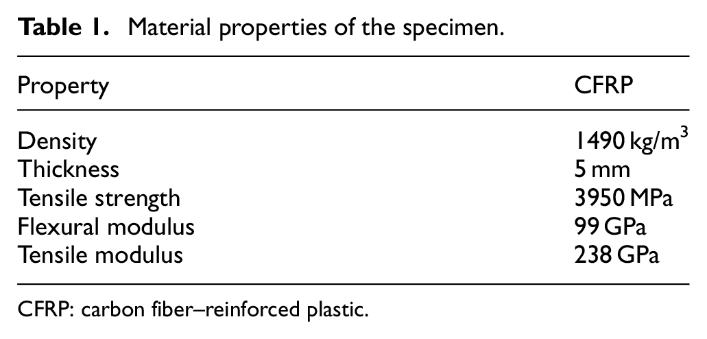
CFRP: carbon fiber–reinforced plastic.
Drill bit material and geometry
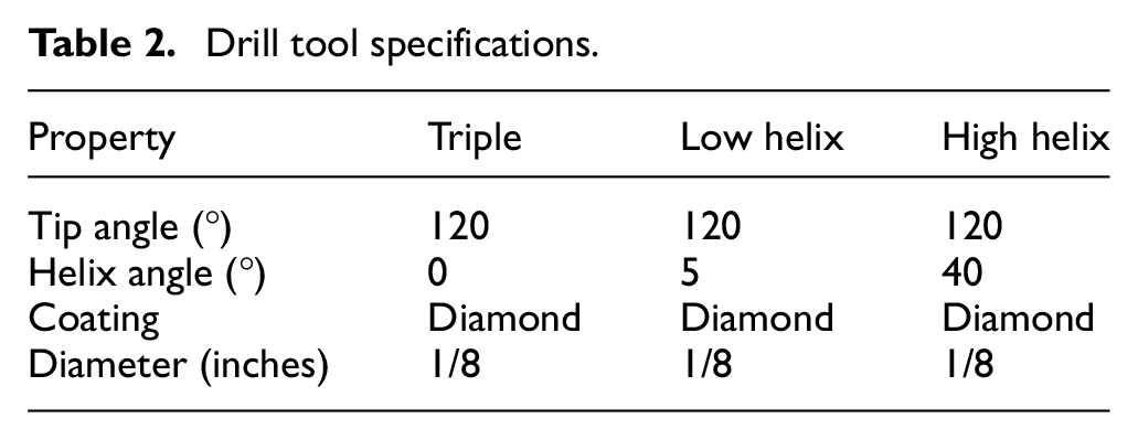
Premium high-performance diamond-coated carbide was used. Regarding the geometry of the tool, three types of twist angles, triple, LH, and high helix (HH), corresponding to 0°, 5°, and 40°, were investigated. The point angle was 120°. The diameter was #30, which corresponded to 3.175 mm. The summary is shown in Table 2, and the geometry of the tool is shown in Figure 1.
Drill tool specifications.
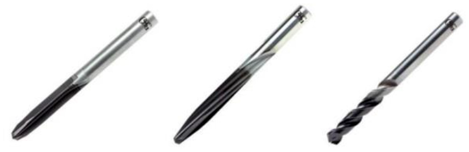
The geometry of the tools.
Experimental setup
The drilling was performed on a three-axis high-speed Tapping Center CNC Litz Hitech TV-600. The revolution of the spindle was 12,000 r/min. A gas lubrication system was set up using two pipes, one for air and CO2, and another for CO2–N2. The pressure of the air was adjusted by a precision air regulator. The pressure of the gas was adjusted by a gas regulator. The air and gas flow were monitored by an electronic airflow meter. The fixture is fabricated for two purposes: quick mounting and temperature monitoring by a thermal camera (model: IRM_P384A3-20). The temperature of the tool drill was observed at two points on the bottom and the top of the specimen.
A model 6100 scanner system was assembled to measure the thrust force. The experimental system is shown in Figure 2. The air nozzle was located at 45° to the vertical and 30 mm from the tip of the drill. The data collected from the force sensor and thermal camera were analyzed by Strain Smart 6000 and Mart IMR-P384A software. The data measurement was collected from the specification of nine holes in the sample. There are four samples for four modes. The analytical value was averaged over three measurements.
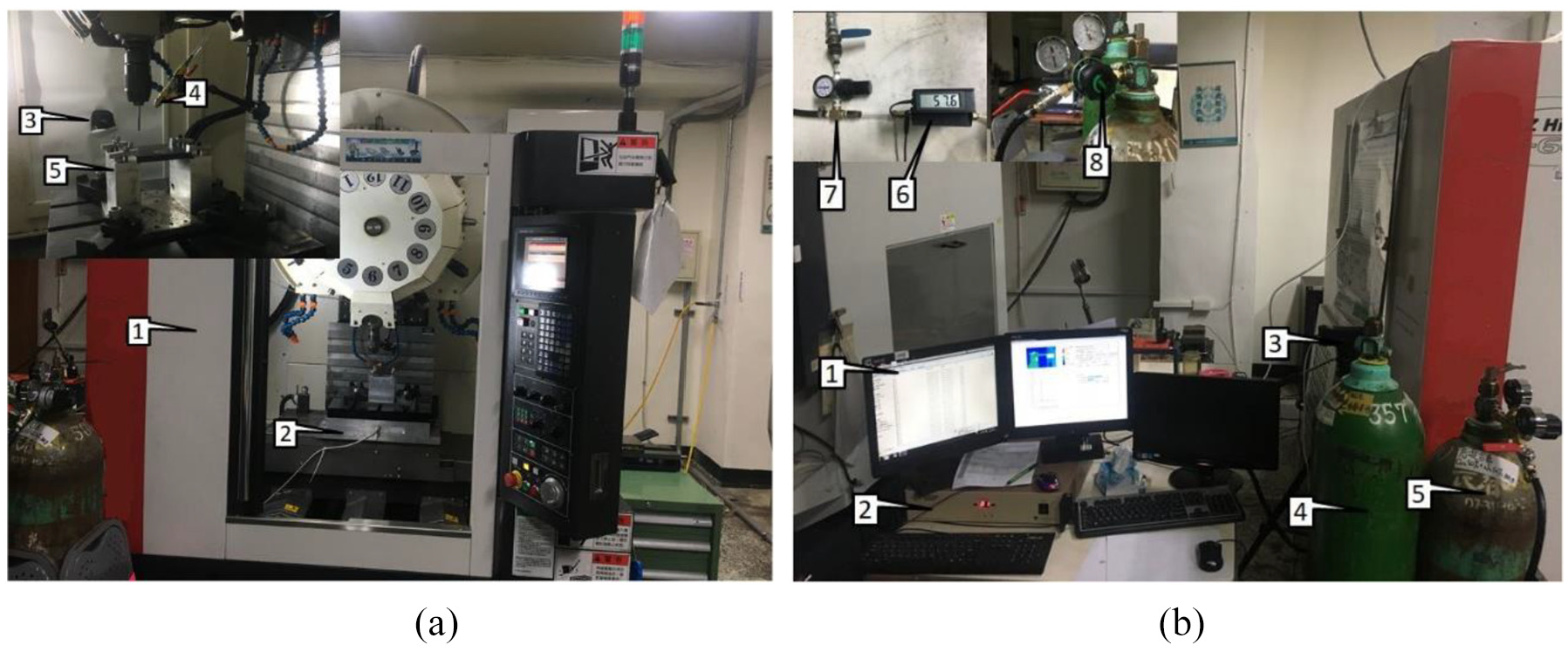
The experimental system for drilling. (a) 1—CNC machine; 2—dynamometer; 3—thermal camera; 4—air nozzle; 5—fixture. (b) 1—computer; 2—DAQ; 3—camera; 4—gas CO2; 5—gas mixture CO2–N2; 6—air flow meter; 7—air regulator; 8—gas regulator.
Selection of cutting parameters
For CFRP machining, the diameter of the tool drill was 1/8″ (corresponding to 3.175 mm). The diameter of the drill tool is three times larger than the thickness of the specimen. Therefore, the counterbore method was used. Using the specification of the tool from the manufacturer, the number of spindle revolutions was set at 6100 r/min. The feed rate was 0.0008–0.002 in./rev. The four modes of the dry, the air, CO2, and CO2–N2 were displayed. The pressure of the air and the gas was 1.5 bar. The flow rate was 57.6 mL/min.
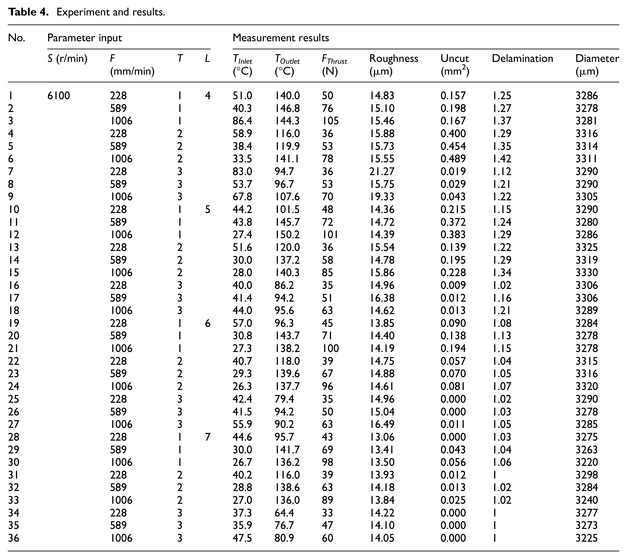
The orthogonal array method is used in this study to design the cutting parameter. The Taguchi method can effectuate optimal and mighty operation in different environments with high proficiency. The drilling parameters and their levels used in the drilling experiment are shown in Table 3. And its measurement results are shown in Table 4.
Parameter process.
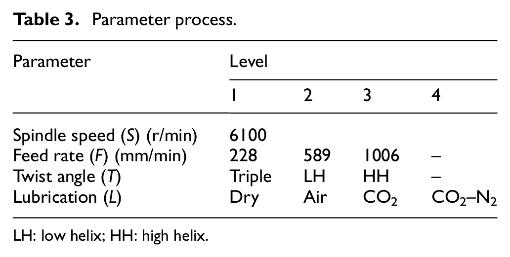
LH: low helix; HH: high helix.
Experiment and results.
Quality assessments
The hole quality was assessed by the uncut fiber, the delamination, and the diameter. The inner hole quality was evaluated by the surface roughness. The roughness was checked by a measuring machine (VK-X200, Keyence). The uncut fiber, the delamination, and the diameter of the hole were measured using a measuring microscope (MF-A2017D, Mitutoyo).
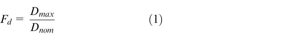
The delamination is inferred from the ratio of the maximum diameter (Dmax) with the nominal diameter (Dnom) of the hole as equation (1). 29 The maximum diameter is calculated by double distance from the center of the nominal hole to the furthest point extension. The nominal diameter and the tool diameter are similar
The UFA was calculated by the area of the fiber that has not been cut, as shown in equation (2) 29

with Anom is the circle area with the diameter of the tool drill. Aex is the area of the surface without areas of uncut fiber.
The UFA and the delamination are illustrated in Figure 3.
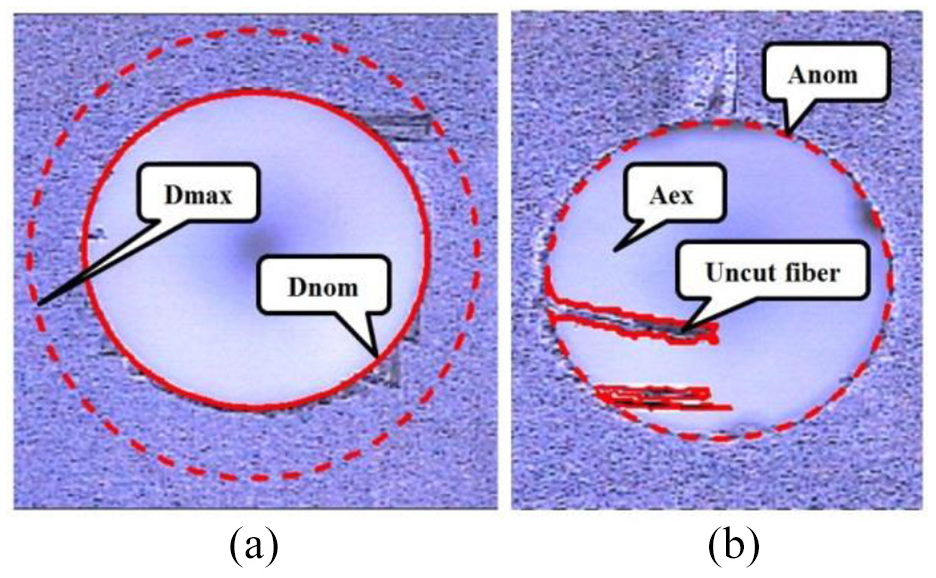
(a) The delamination and (b) the uncut fiber.
Results and discussion
The thrust force analysis
The thrust force was increased with cryogenic machining. 30 As shown in the data collected from the experiments in Table 4, when the feed rate was increased, the thrust force was also increased as shown in Figure 4. Under the parameters shown in Table 2, the maximum thrust force was 105 N with the triple tool. The spindle speed was 6100 r/min. The operation is in dry mode. The feed rate was 1006 mm/min. The minimum thrust force was 33 N with the HH tool. The operation is in CO2–N2 mode. The feed rate was 228 mm/min. An example is showed in Figure 5. The tool is the triple. The operation is in air mode. The spindle speed was 6100 r/min, and the feed rates were 228, 589, and 1006 mm/min. The corresponding thrust forces were 48, 72, and 101 N.
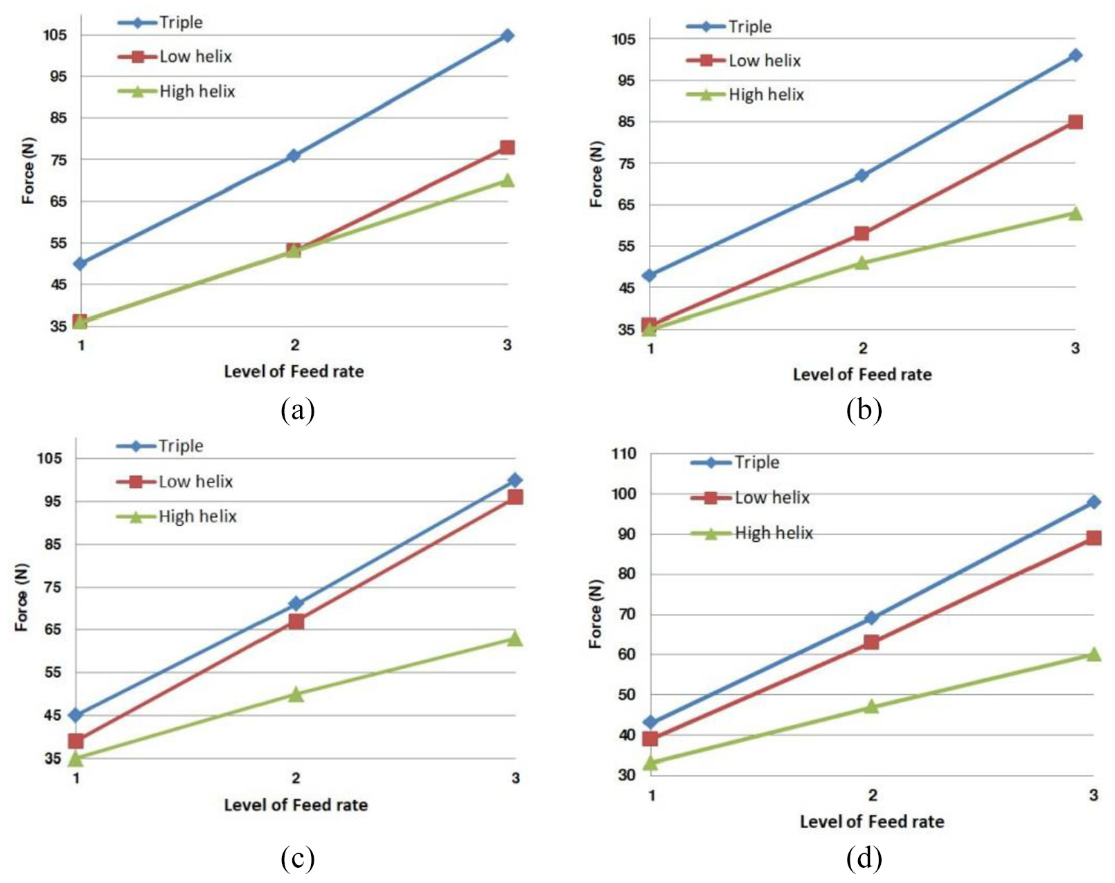
The thrust force in four modes with the three level of feed rate: (1) F = 228 mm/min, (2) F = 589 mm/min, and (3) F = 1006 mm/min. (a) Dry mode, (b) air mode, (c) gas CO2 mode, and (d) gas mixture CO2–N2 mode.
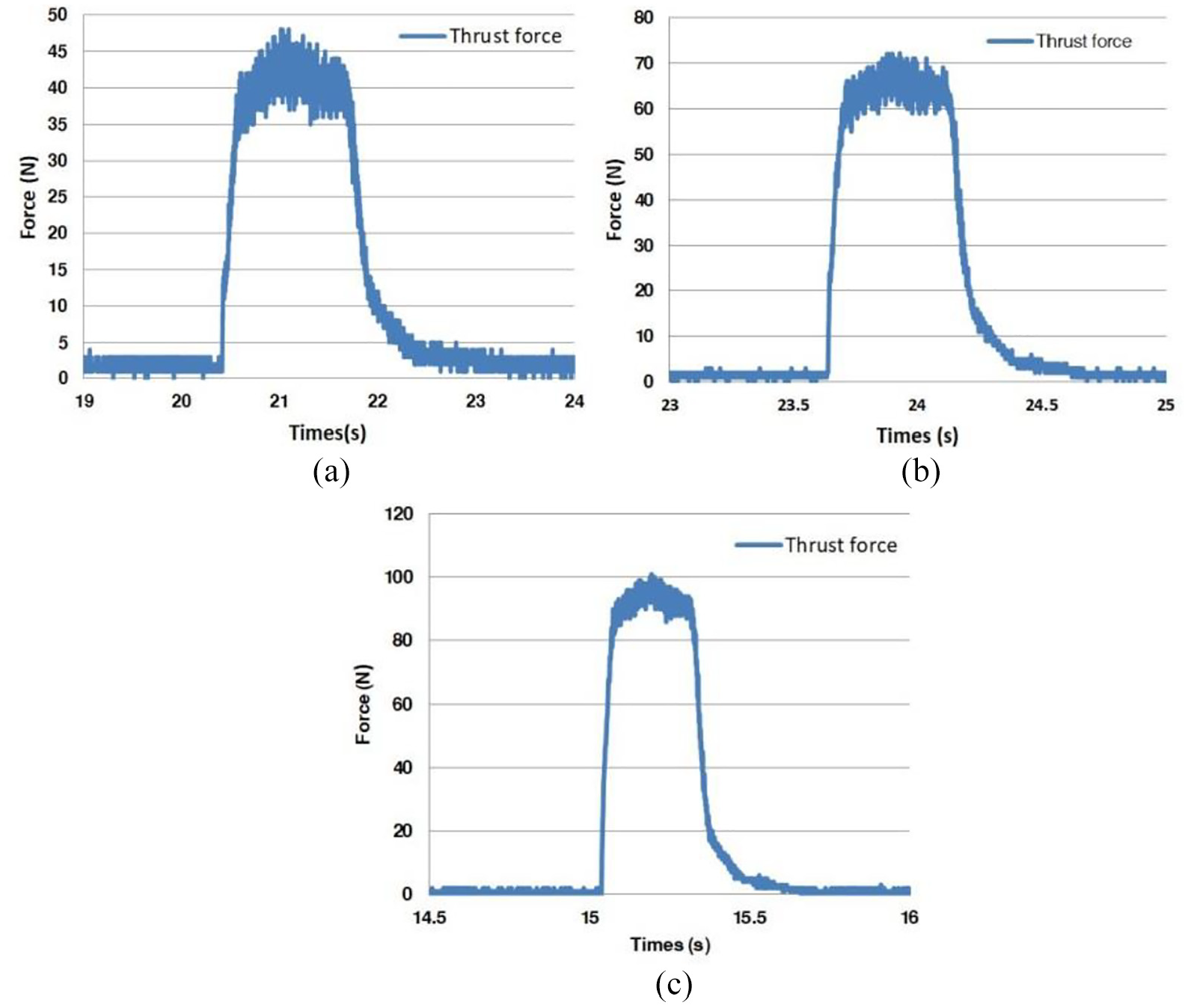
The thrust force in the fresh air-drilling mode with the triple tool at a spindle speed of 6100 r/min: (a) F = 228 mm/min, (b) F = 589 mm/min, and (c) F = 1006 mm/min.
In the dry mode and air mode, the thrust force was not clearly different when speeding up the feed rate. The HH tool is significant at all levels of feed rates. As shown in Figure 6, for each feed rate, with the LH tool, the maximum thrust force was equal to 39, 67, and 96 N, respectively. With the CO2 mode, the minimum thrust force in the dry mode was equal to 36, 53, and 78 N, respectively.
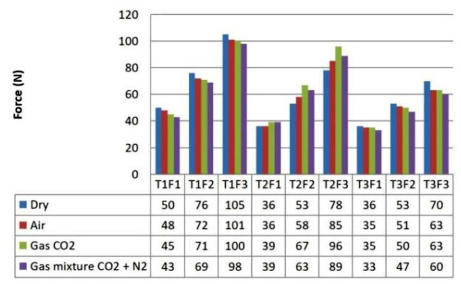
The thrust force for each experimental case.
The experiment result is different from the triple tool and HH tool. The thrust force is decreased. The difference between the air mode and CO2 mode was not clear; however, it was significant with CO2–N2. The minimum thrust force was equal to 33 N at a feed rate of 228 mm/min. In terms of the shape influence, the maximum thrust force was found using the triple tool and the minimum was found using the HH tool.
The temperature analysis
The temperature result in Table 4 was measured at the position of the inlet hole and the outlet hole. Figure 7 shows that the temperature at the inlet was increased at the beginning of the process. The value of the temperature at the inlet and the outlet was closer when the feed rate was increased. At the end of the process, the temperature of the inlet was increased rapidly in a short time. This was caused by the drilling tool being pulled up at the end of the process. The thermal camera still captured the temperature at that time. In this case, the temperature was increased when the feed rate was increased. The temperature at the inlet was 40 °C, 41.4 °C, and 44 °C, and the temperature at the outlet was 86.2 °C, 94.2 °C, and 95.6 °C, respectively.
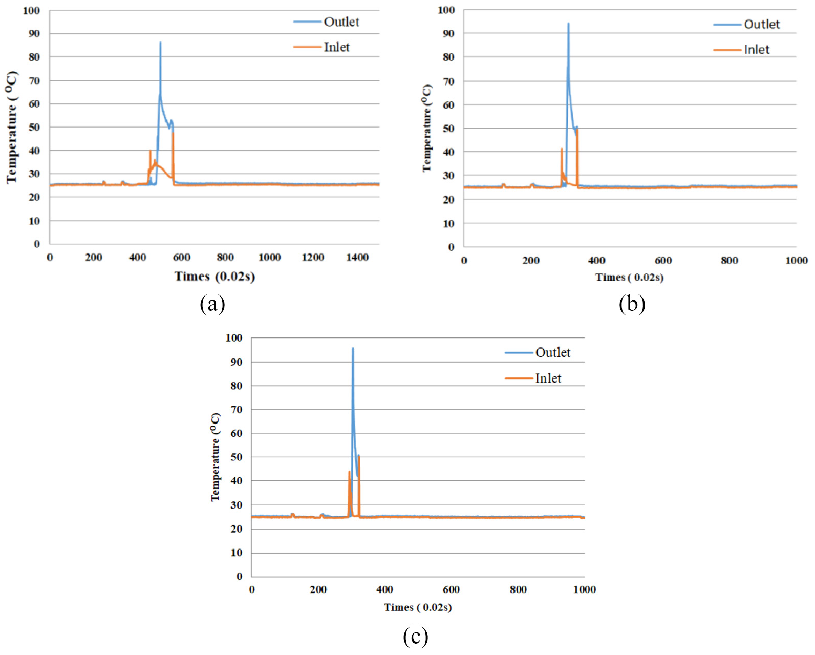
The temperature during the air-drilling mode using the high helix tool at a spindle speed of 6100 r/min:(a) F = 228 mm/min, (b) F = 589 mm/min, and (c) F = 1006 mm/min.
At the inlet and the outlet of the hole in the dry mode, the temperature is shown in Figure 8. With the LH tool, the temperature at the inlet of the hole is decreased. But it is increased at the outlet of the hole. The temperature at the outlet showed little difference between each tools. With the triple tool and the LH tool, the increment of the temperature was noticeable when speeding up the feed rate. With the HH tool, the increment of the temperature was not significant.
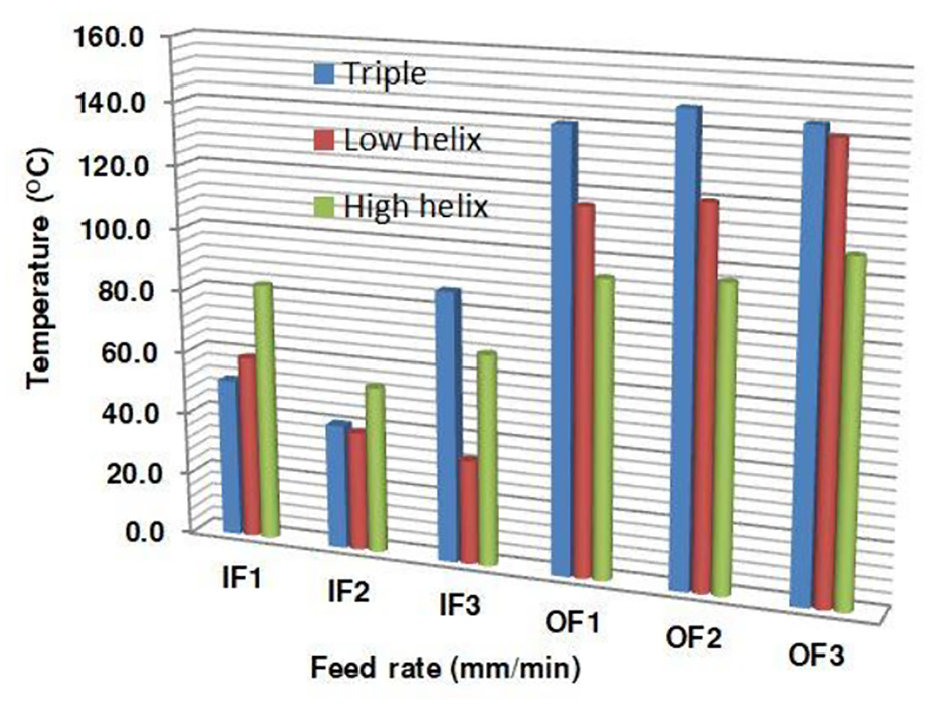
The temperature at inlet and outlet hole in dry mode.
At the inlet and the outlet of the hole in the air mode, the temperature data were as shown in Figure 9. The temperature differences at the inlet and the outlet of the hole using the triple tool and the LH tool were remarkable when the feed rate was increased. The temperature of the HH tool was relatively stable, indicating that the air helped to exchange heat during the process.
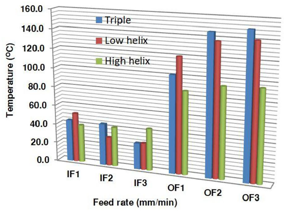
The temperature at the inlet and outlet hole in air mode.
In the CO2 mode, at the outlet and the inlet of the hole, the temperature change is illustrated in Figure 10. In this mode, the tool was cooled during the process. The temperature at the outlet of the hole is not increased as in the dry mode with low feed rate. It was lower than the air mode but was insignificant. When the feed rate was increased, a more pronounced difference in temperature was displayed. The HH tool was still remarkable.
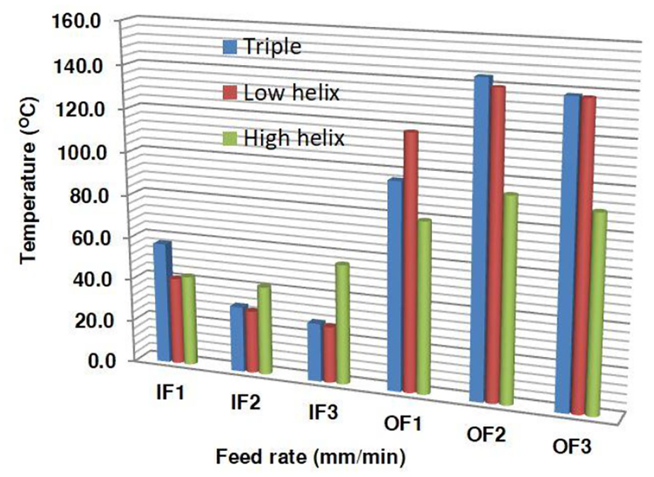
The temperature at the inlet and outlet hole in CO2 mode.
At the inlet and the outlet hole in the CO2–N2 mode, the temperature changed, as shown in Figure 11. The effect of the CO2–N2 mode was not obvious with the triple tool and the LH tool, but it had a clear effect with the HH tool. The temperatures at the inlet and the outlet of the hole were reduced to about 40 °C and 76 °C, respectively.
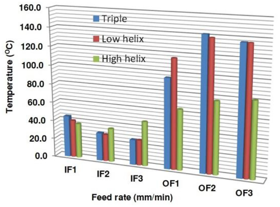
The temperature at the inlet and outlet hole in CO2–N2 gas mixture mode.
The delamination analysis
According to the experiment results in Table 4, the delamination occurred primarily on the top surface. The delamination, Fd, was calculated using equation (1), and Dmax and Dnom were measured using a measuring microscope. An example is shown in Figure 12.
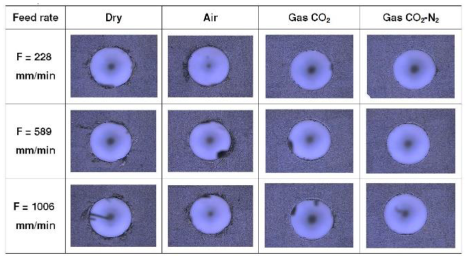
The delamination at the top surface using the low helix tool.
Figure 13 shows that the delamination increased when the feed rate was increased; however, it was not significant between the dry mode and the air mode. The appearance was better in the CO2 mode and the CO2–N2 mode. For the dry mode (cases 1, 2, 3) and the air mode (cases 4, 5, 6), the delamination by the triple tool was lower than the delamination by the LH tool. In the gas CO2 mode and gas mixture CO2–N2 mode, the delamination by the LH tool was significantly reduced. The delamination by the HH tool had little difference, and its performance was better than the other cases.
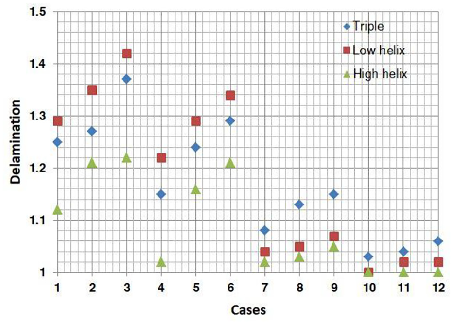
The delamination of the hole by three types of tools at three feed rate levels in four modes as the parameters in Table 3.
The uncut fiber analysis
The UFA was considered as an index to assess the drill hole quality of CFRP composite. The value of the UFA was calculated using equation (2). Using a measuring microscope, the areas of uncut fibers could be calculated directly from the software (AIM3000, Mitutoyo) through image processing by the points selected along the close contour of the UFA.
As the experiment results in Table 4 show in Figure 14, with the triple tool, the UFA increased when the feed rate was increased in the air, CO2, and CO2–N2 modes. In the dry mode, the UFA both increased and decreased, and the UFA with the triple tool was smaller than the UFA with the LH tool. The performance of the HH tool was significant in all cases. In the CO2–N2 mode, the difference between each case showed a positive convergence.
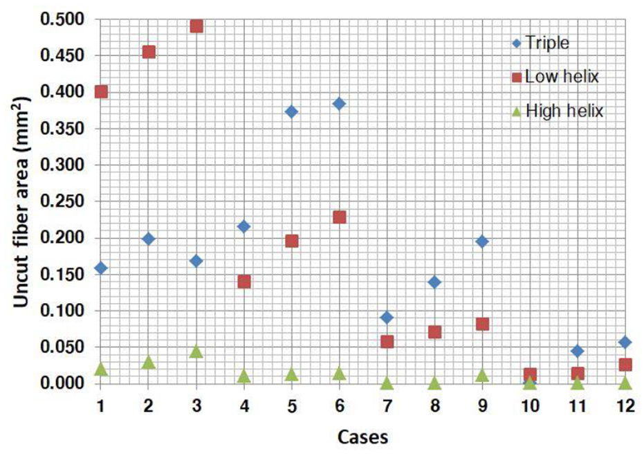
The uncut fiber area of the hole by three types of tools at three feed rate levels in four modes as the parameters in Table 3.
The diameter analysis
As the results of the experiment in Table 4, the effect of the triple tool was cleared. This result may have been due to the effect of the length of the straight flute to the tolerance value of the hole. The values obtained were approximately equal between triple tool and HH tool. The feed rate did not clearly affect the size of the hole. The drilling process in the CO2 mode and in the CO2–N2 mode was better in all cases. This result is illustrated in Figure 15. The hole diameter value varied from 3220 μm to 3330 μm, and the nominal size of the drill bit was 3175 μm.
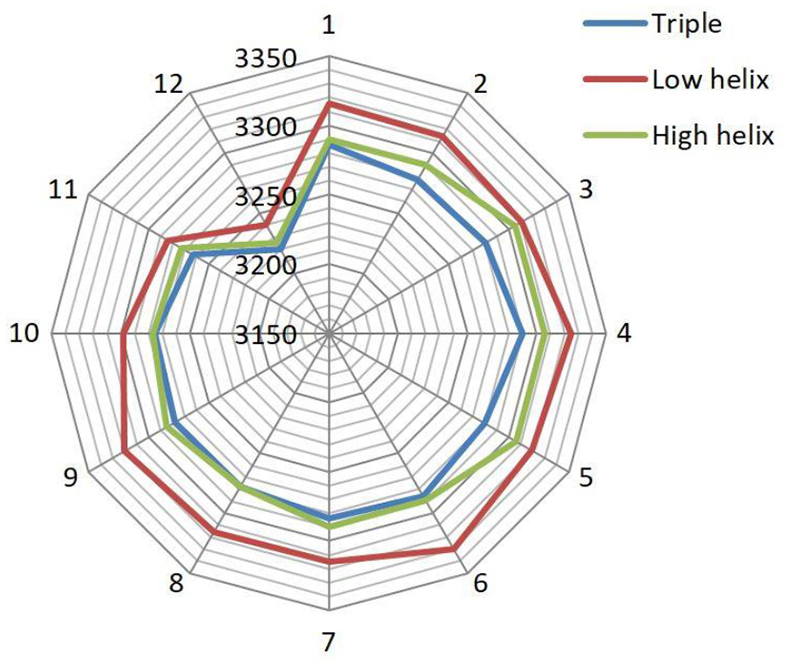
The diameter of the holes by three types of tools at three feed rate levels in four modes as the parameters in Table 3.
The roughness analysis
The result of the roughness measurement in Table 4 is shown in Figure 16. The collected data indicated that the influence of lubrication had no obvious influence on surface roughness. The influence of the feed rate was similar to that of the lubrication. In the dry mode and the CO2–N2 mode, with the triple tool, the roughness of the surface increased when the feed rate was increased. It is different in air mode and CO2 mode. The roughness of the surface is higher at the average feed rate. The difference in the roughness value was not significant. Material factors and material homogeneity were found to significantly affect the quality of machining surfaces. In general, the performance of the triple tool in CO2–N2 mode was better than other cases.
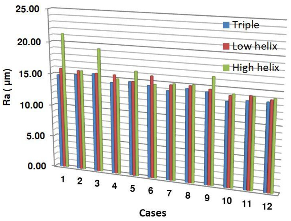
The roughness of the surface of the holes by three types of tools at three feed rate levels in four modes as the parameters in Table 3.
In case 1 and case 3 (machining in the dry mode with the HH tool), the roughness of the surface when machining by the HH tool was unusually changed, and the phenomenon of surface peeling existed. It could be due to the keyhole or porosity in the material.
The surface roughness of case 10 (in the CO2–N2 mode with the triple tool at a feed rate of 228 mm/min) is better than the other cases and was equal to 13.06 μm. The result is illustrated in Figure 17.
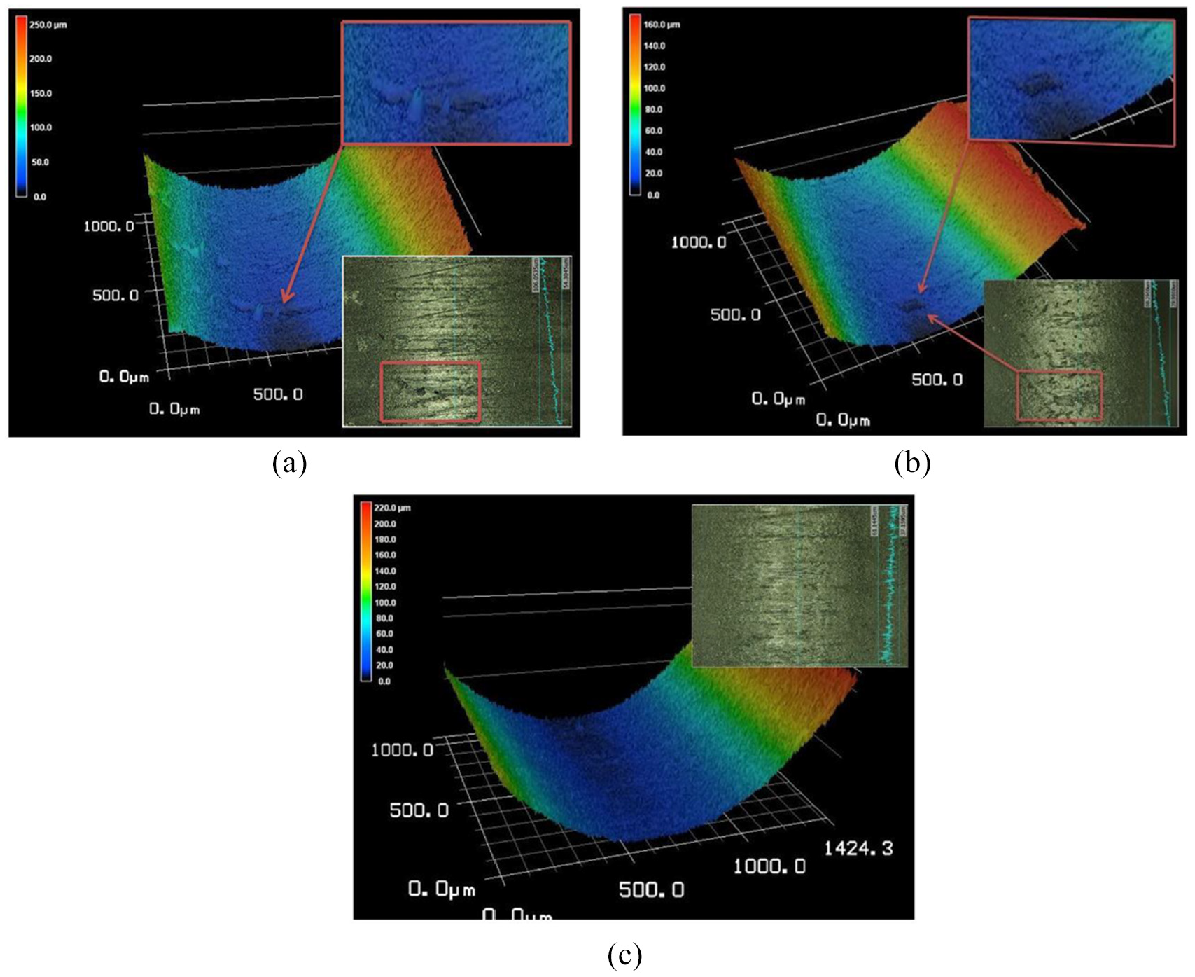
The surface roughness for case 1, case 3, and case 10: 21.27, 19.33, and 13.06, respectively—(a) case 1 in Figure 16, HL tool, dry mode, feed rate (228 mm/min); (b) case 3 in Figure 16, HL tool, dry mode, feed rate (1006 mm/min); and (c) case 10 in Figure 16, triple tool, CO2−N2 mode, feed rate (228 mm/min).
Conclusion
Regarding the technology of processing CFRP composites, the materials of drilling tools are always focused in many research studies. In this study, based on empirical data and data processing, the shape of the drill bit, namely, the twist angle of the flute, also has an important part in assessing the drill hole quality as well as the cutting force and temperature generated during the machining process. According to the drilled hole quality, geometry of the hole, the delamination, the UFA, and the surface roughness were appraised. The delamination in the dry mode and that in the air mode by the triple tool was lower than the delamination by the LH tool. In the CO2 mode and the CO2–N2 mode, the delamination by the LH tool was significantly reduced. The delamination by the HH tool showed little difference, and its performance was better than the other cases.
The UFA with the triple tool in the dry mode was smaller than the UFA with the LH tool. The performance of the HH tool was significant in all cases. In the CO2–N2 mode, the difference between each case showed positive convergence. Regarding the geometric accuracy, the performance of the triple tool was clear in evaluating the quality. The values obtained were approximately equal between the triple tool and the HH tool. The process in CO2 mode and the CO2–N2 mode was better in all cases.
The performance of the gas lubrication in evaluating the roughness surface was negligible. The triple tool performed better than the LH tool and the HH tool.
Regarding force and temperature, the HH tool was significant at all feed rates. The thrust force was increased with cryogenic machining. The effect of the CO2–N2 mode was not obvious with the triple tool and the LH tool; however, it had a clear effect with HH tool.
According to the results of the above study as well as the benefits of cryogenic assist in machining CFRP composite, the CO2–N2 gas mixture showed a positive effect on the machining process, thus making it fully applicable in CFRP composite processing and contributing to reducing CO2 emissions into the atmosphere to protect the environment.
Footnotes
Acknowledgements
The authors acknowledge and thank the Ministry of Education of the Republic of China for their partial financial support of this study under contract number E0002B and the Ministry of Science and Technology of the Republic of China under contract number MOST 108-2622-E-992-009-CC3.
Declaration of conflicting interests
The author(s) declared no potential conflicts of interest with respect to the research, authorship, and/or publication of this article.
Funding
The author(s) received no financial support for the research, authorship, and/or publication of this article.