
Abstract
The fault-crossing tunnel in meizoseismal area is directly subjected to strong ground motion, which leads to the failure of the tunnel lining. In order to improve the seismic safety of tunnel, fiber-reinforced concrete is applied to tunnel lining in this article. Taking the section of Zhongyi tunnel crossing Wanlong fault as an example, seismic performance of fiber-reinforced concrete tunnel lining was studied by finite difference numerical calculation software FLAC3D. The seismic displacement, stress response, and side wall convergence of secondary lining structures which are plain concrete, steel fiber-reinforced concrete, and steel-basalt hybrid fiber-reinforced concrete were comparatively analyzed. Moreover, the safety factor of each lining structure was investigated with the present numerical model. With the obtained data, seismic performance of steel-basalt hybrid fiber-reinforced concrete secondary lining is better than that of steel fiber-reinforced concrete secondary lining. The results may provide references for seismic design of fault-crossing tunnels in meizoseismal area.
Introduction
Due to regional influence and various restrictions, a tunnel will inevitably cross fault fracture zones in meizoseismal area. The tunnel is directly subjected to strong ground motion and the dislocation of the fault, which leads to the failure of the tunnel lining. 1 There are many examples of fault-crossing tunnel damage in earthquakes. 2 In Chi-Chi earthquake (Taiwan, China), under the dislocation of the Chelongpu fault, the Shigangba tunnel was damaged seriously near the fault plane. 3 In Wenchuan earthquake (Sichuan, China), although none of the tunnels in the area were found to have collapsed during the powerful shaking motions, some tunnels’ lining were badly damaged during the earthquake. For example, Longdongzi tunnel located near Dujiangyan City was damaged after the earthquake. 4 Plain concrete (PC) lining crown collapsed in construction phase, steel reinforced concrete lining sidewall cracked and spalled during operation period. 5 Therefore, improving seismic performance of tunnels crossing fault fractured zones has attracted wide attention to investigators. The study on the dynamic response and seismic damage of tunnel linings under the seismic waves found that crack patterns revealed in the damage analysis of the numerical model were in line with the field investigation of several mountain tunnels damaged during the Wenchuan earthquake (Sichuan, China). 6 Seismic analysis is important for safety evaluation of the tunnels during earthquakes. 7 At present, several models and methods are presented, and also, experts have done lots of research on the earthquake resistance and seismic technology of tunnel crossing fault in strong earthquake area. Model experiments and numerical simulation were conducted to study the tunnel setting up shock absorption layer.8–10 The grouting reinforcement mechanism and grouting material of surrounding rock in the fault tunnel is studied by numerical simulation. 11 Three-dimensional seismic response of a deep cylindrical tunnel and the effect of voids was obtained, 12 which shows that large stress concentration caused by voids is highly correlated with seismic damage of tunnels. Research suggests that reinforcement of the lining is crucial to prevent the seismic damage of tunnels. To study the seismic behavior of tunnels, proper modeling of lining can be of great importance. Fiber-reinforced concrete (FRC) is a kind of composite material which is composed of fibers dispersed in concrete. A variety of fibers (fiberglass, steel fiber, nylon, etc.) is effective in improvement of concrete mechanical properties such as compression, tension, and shear resistance. 13 These fibers induce internal connections which prevent the development of cracks. 14 It is a good substitute for seismic fortification of tunnel lining structure by improving the performance of concrete. 15 Steel fibers display better seismic performance over conventional steel rebar in reinforced concrete linings. 16 The effects of steel fiber-reinforced concrete (SFRC) composites on the flexural response of segmental joints under seismic actions are investigated numerically based on experimental results 17 and deriving R-factor values to facilitate its seismic design. 18 The seismic behavior of tunnel lining with PC, steel reinforced concrete, and polypropylene fiber-reinforced concrete (PFRC) was studied by a series shaking table tests. 6 Fiber is able to relieve the stress concentration in the lining structure which is highly correlated with seismic damage of tunnel.
In this article, the seismic behavior of FRC tunnel lining is studied by finite difference numerical method. On the basis of that, applying the FRC in tunnel lining, based on the Wanlong fault section of Zhongyi tunnel of Lijiang–Shangri-La Railway, the seismic displacement, stress response of PC, SFRC, and steel-basalt hybrid fiber-reinforced concrete (SBHFRC) structures were compared and analyzed. Moreover, the safety factor of the lining structure was investigated. Based on the obtained results, the seismic effect of FRC was analyzed, followed by suggested solutions.
FLAC3D simulation method
FLAC3D (Fast Lagrangian Analysis of Continuum) is a three-dimensional finite difference program, an extension of the FLAC2D, 19 which can simulate the mechanical properties and dynamic analysis of three-dimensional structures of soil, rock, and other materials. Lagrangian algorithm which is very suitable to simulate large deformation problems since it divides the computational region into several hexahedral elements. Each element follows a specified linear or nonlinear constitutive relationship under given boundary conditions. If the element stress causes the material to yield or produce plastic flow, the element mesh can be deformed with the deformation of the material. 20
FLAC3D adopts explicit finite difference scheme to solve the differential equation, and hybrid-discrete partition technique. The mixed discrete method is used to simulate plastic failure and plastic flow. This method is more accurate and reasonable than the discrete integration method commonly used in finite element method. Even if the simulation system is static, the dynamic motion equation is still used, which makes FLAC3D simulation of physical instability process without numerical obstacles. Therefore, the explicit solution takes almost the same time to solve the nonlinear stress–strain relationship as the linear constitutive relationship, while the implicit solution will take a long time to solve the nonlinear problem. Moreover, it does not need to store stiffness matrices, which means that multi-element structures can be solved using medium capacity memory. Simulating large deformation problems hardly consumes more computing time than small deformation problems because no stiffness matrices need to be modified. This allows the derivation of momentum equilibrium for each node to create equilibrium with time steps. 21
FLAC3D can accurately simulate the yield, plastic flow, softening, and large deformation of materials, especially in the fields of elastoplastic analysis, fluid–solid coupling process, large deformation analysis, and simulation of construction process. It is the most effective tool for large deformation nonlinear problems in practice.
Numerical model test
Geological conditions of Wanlong fault section of Zhongyi tunnel
The Zhongyi tunnel of Lijiang–Shangri-La Railway is 14,745 m in length, the longest tunnel on the whole line. It is located in the transition zone from Qinghai–Tibet Plateau to Yunnan–Guizhou Plateau. 22 The tunnel is located in the special geographical location, with frequently natural disasters such as debris flow, landslides, and earthquakes. Affected by the fault zone at the western foot of Yulong Xueshan Mountain, large deformation of surrounding rock is easily caused under high geostress in meizoseismal area. The numerical model established in the article is the Wanlong fault section of Zhongyi tunnel. Wanlong fault is located in the area from Xinshan to Hutiaoxia. It is located in the region of seismic fortification of 8°,23,24 strikes near S∼N, tends to E∼NEE, and dips 65°–75°. The upper wall is basalt (Pβ), sandstone with shale (T1l), and the lower wall is sandstone (T1), deviated basalt with sandy slate (Tβ), all of which are Class IV surrounding rock in China code. 25 The rock mass characteristics of the Class IV surrounding rock include the broken extremely hard rock, the broken or broken hard rock, the relatively complete or broken soft rock or soft hard rock interbedding mainly composed of soft rock, and the complete or relatively complete soft rock. The fracture bandwidth of the fault is about 30 m. It is mainly composed of breccia, which is Class V surrounding rock with loose cement consisting of iron mud and gravel soil.
Numerical model
The calculation model is established to simulate the key section of Zhongyi tunnel across Wanlong fault. The tunnel model is an elastic–plastic model, the tensile behavior of material model adopts the tensile strength of fiber, regardless of the tensile strength of concrete. After the fiber concrete cracks, the fiber still adopts the original model. The yield criterion used is Mohr–Coulomb criterion. Because of the lithology of surrounding rock in the location of tunnel, Mohr–Coulomb criterion reflects the real failure behavior and mechanical properties of rock mass, which is partial to safety. However, the use of hardened soil around the tunnel does not meet the site conditions and surrounding rock characteristics. The depth of the tunnel is 40 m, the depth of longitudinal excavation is 150 m, the thickness of the bedrock at the bottom of the tunnel is 20 m, and the width of the left and right sides of the tunnel are five times the width of the tunnel, about 35 m. The model uses swept method to mesh and hexahedral solid element. Considering the calculation accuracy and scale, the grid was divided into 20 parts. After trial calculation, this kind of grid is most suitable for this example. The mesh size of surrounding rock and tunnel is 1 m in X direction, 1 m in Y direction, and 8 m in Z direction. The mesh size of primary support and secondary lining is one cell with thickness of 0.2 m.
The dip angle of the fault is approximately 75°. The surrounding rock consists of two parts, the fracture zone is between them with width of 10 m. The fault is an inactive fault, regarded as a weak interlayer. In fault modeling, the fault is regarded as weak surrounding rock by modifying attribute parameters, so as to establish fault zone. The surrounding rock boundaries are fully constrained, while the upper boundary is unconstrained. The computational model is shown in Figure 1, and the tunnel model is shown is Figure 2.

Vertical section view of fault model with tunnel.
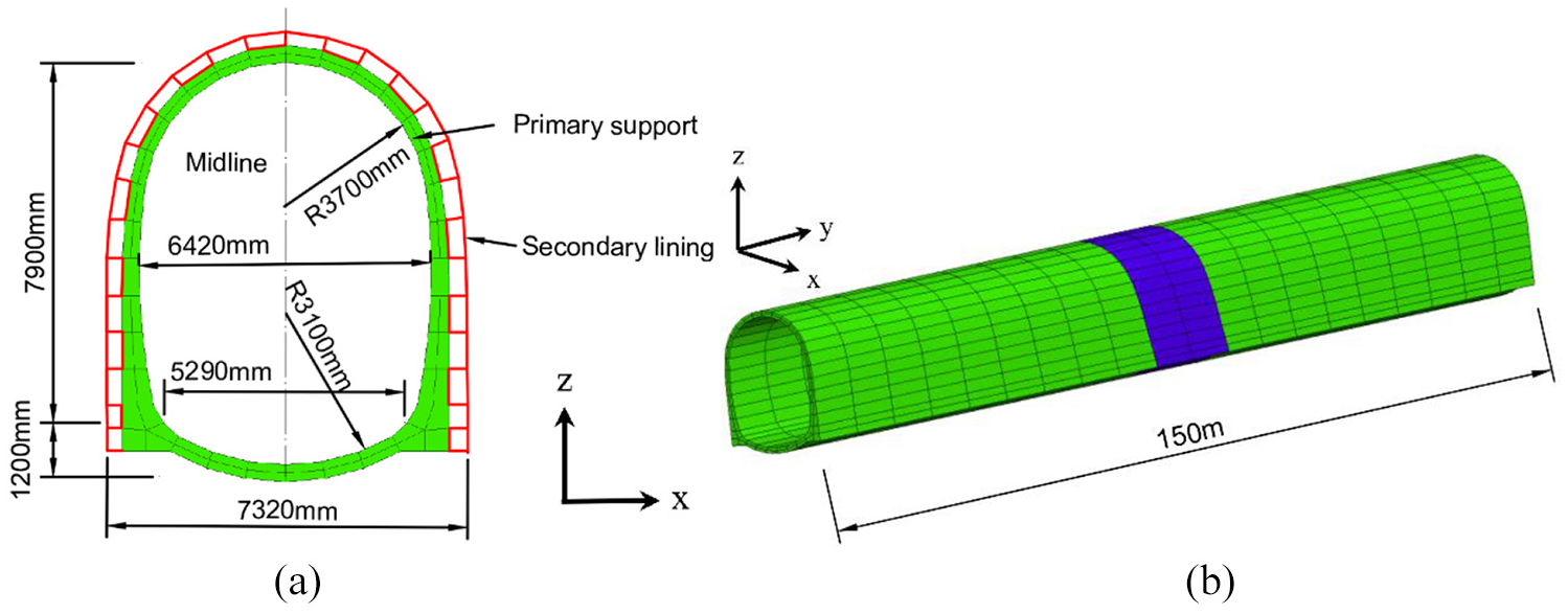
Tunnel model: (a) cross section; (b) grid division.
The tunnel structure of fault section adopts curved wall with inverted arch and composite lining. The initial support is C25 shotcrete with a thickness of 25 cm, which has Young’s modulus of 28 GPa and Poisson’s ratio of 0.2. The secondary lining is C30 mode concrete with a thickness of 45 cm, which has Young’s modulus of 30 GPa. Based on the actual geological survey data and experimental results, the calculation parameters of the model were obtained as shown in Table 1.
Parameters of the model.

SFRC: steel fiber-reinforced concrete; SBHFRC: steel-basalt hybrid fiber-reinforced concrete.
Class in code for design of road tunnel (TB 10003-2005). 22
Intensity class in code for design of concrete structures (GB 50010-2010). 23
Simulation condition
The free field boundary condition is chosen to simulate the calculation, and the local damping coefficient used is 0.1571. Using conventional dynamic loading method, seismic waves in three directions (x, y, z) were simultaneously transmitted to the upper structure through the bottom of the model. The three directions were vertical, lateral, and longitudinal, respectively, corresponding to the x, y, z direction of the model. Acceleration wave of Wenchuan earthquake (Wolong station) was selected as seismic input, which is standardized according to intensity of 9° earthquake. 26 Duration reduces to 15 s. After filtering and baseline correction, the acceleration time history curves are shown in Figure 3.

Time history curves of acceleration: (a) x direction; (b) y direction; and (c) z direction.
When the tunnel model is subjected to earthquake waves, 10 monitoring sections are set up along the longitudinal direction of each tunnel, which are named S1, S2, up to S10. The displacement and internal force values of measuring points at eight positions, such as tunnel vault, left arch shoulder, left sidewall, left arch foot, right arch shoulder, right sidewall, right arch foot, and inverted arch, were extracted for seismic effect analysis and safety factor calculation. The layout of measuring points is shown in Figure 4.
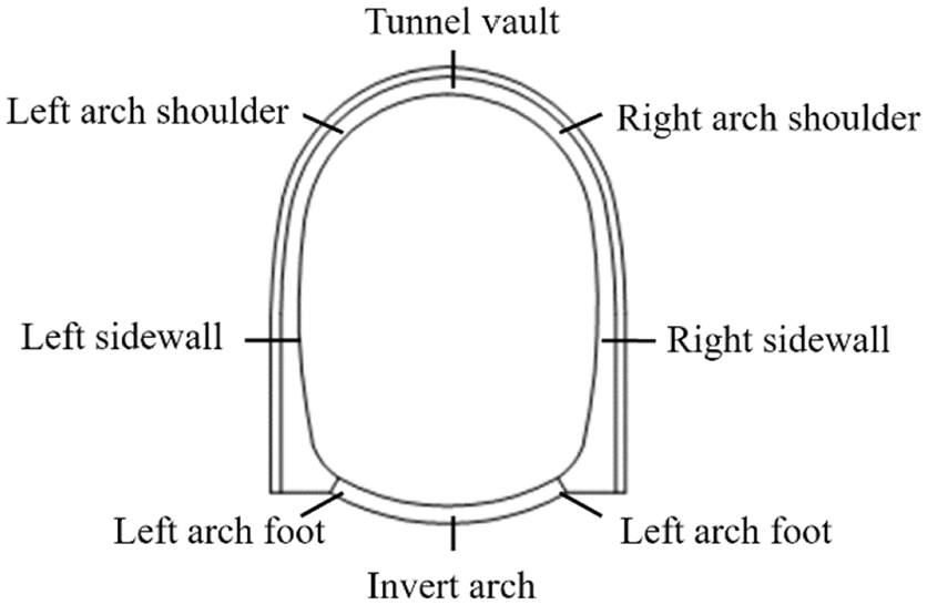
Layout of measuring points.
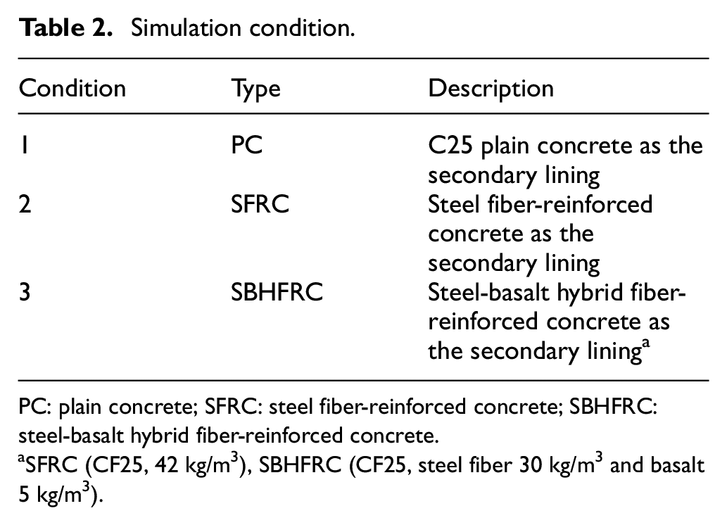
For the same tunnel model, subjected the same ground motion input, C25 PC, SFRC, and SBHFRC were taken separately as the tunnel’s secondary lining. The seismic displacement and stress response of measuring points in the tunnel lining were investigated under the three working conditions as shown in Table 2.
Simulation condition.
PC: plain concrete; SFRC: steel fiber-reinforced concrete; SBHFRC: steel-basalt hybrid fiber-reinforced concrete.
SFRC (CF25, 42 kg/m3), SBHFRC (CF25, steel fiber 30 kg/m3 and basalt 5 kg/m3).
Results and discussion
Seismic displacement
Displacement of fractured zone
The displacement contour of tunnel structure in fault fractured zone under different working conditions was extracted, as shown in Figures 5–7.

Vertical displacement contour of secondary lining structure: (a) PC; (b) SFRC; and (c) SBHFRC.

Lateral displacement contour of secondary lining structure: (a) PC; (b) SFRC; and (c) SBHFRC.

Longitudinal displacement contour of secondary lining structure: (a) PC; (b) SFRC; and (c) SBHFRC.
The maximum displacement of the secondary lining structure was extracted, and the seismic effect of working conditions 2 and 3 was calculated (compared with working condition 1), as shown in Table 3. From Table 3, it can be seen that the vertical and transverse displacement values of the secondary lining structure have decreased after using FRC lining, in which the vertical displacement of SFRC was reduced by 1.64%, the transverse displacement was reduced by 0.68%, the longitudinal displacement was reduced by 11.32%, the vertical displacement of SBHFRC was reduced by 0.97%, and the transverse displacement was reduced by 0.97% compared with the PC. The displacement decreased by 0.39%, and the longitudinal displacement decreased by 7.54%. In terms of structural displacement control, the seismic effect of SFRC secondary lining is slightly better than that of SBHFRC secondary lining.
Maximum displacement value and seismic effect of second lining structure.

PC: plain concrete; SFRC: steel fiber-reinforced concrete; SBHFRC: steel-basalt hybrid fiber-reinforced concrete.
Displacement of fractured zone
The convergence of the side walls of each monitoring section of the tunnel under different working conditions was extracted, as shown in Figure 8.

Convergence value of side wall.
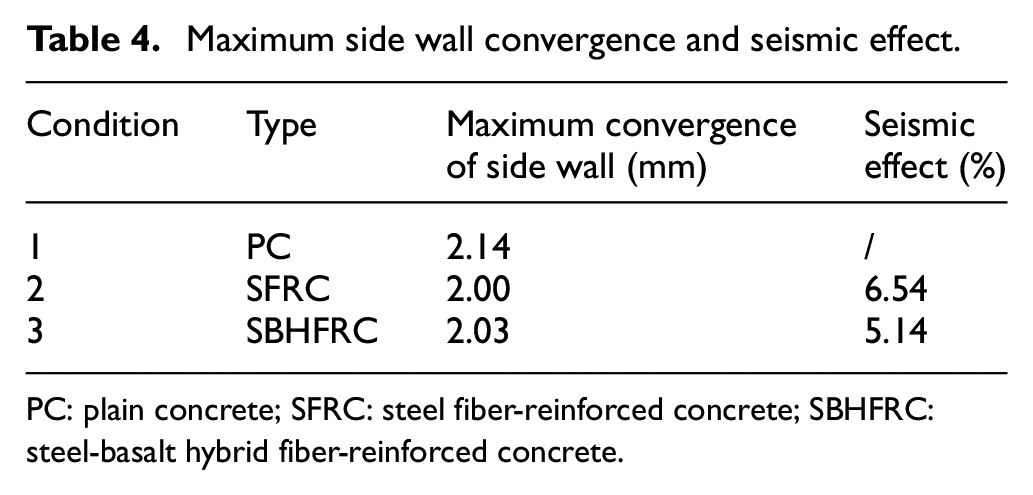
The maximum convergence value of the side wall of the second lining structure was extracted, and the seismic effect of working conditions 2–3 was calculated (compared with working condition 1), as shown in Table 4. From Table 4, it can be seen that the maximum convergence value of PC secondary lining side wall is 2.14 mm. After using FRC lining, the convergence value of side wall of secondary lining structure decreases. The convergence value of SFRC is 2.00 mm, the seismic effect is 6.54%, the convergence value of SBHFRC is 2.03 mm, and the seismic effect is 5.14%. From the point of view of controlling the convergence of side walls, the seismic effect of SFRC lining is slightly better than that of SBHFRC lining.
Maximum side wall convergence and seismic effect.
PC: plain concrete; SFRC: steel fiber-reinforced concrete; SBHFRC: steel-basalt hybrid fiber-reinforced concrete.
Stress response
Principal stress
The principal stress contour of tunnel structure in fault fractured zone under different working conditions was extracted, as shown in Figures 9 and 10.
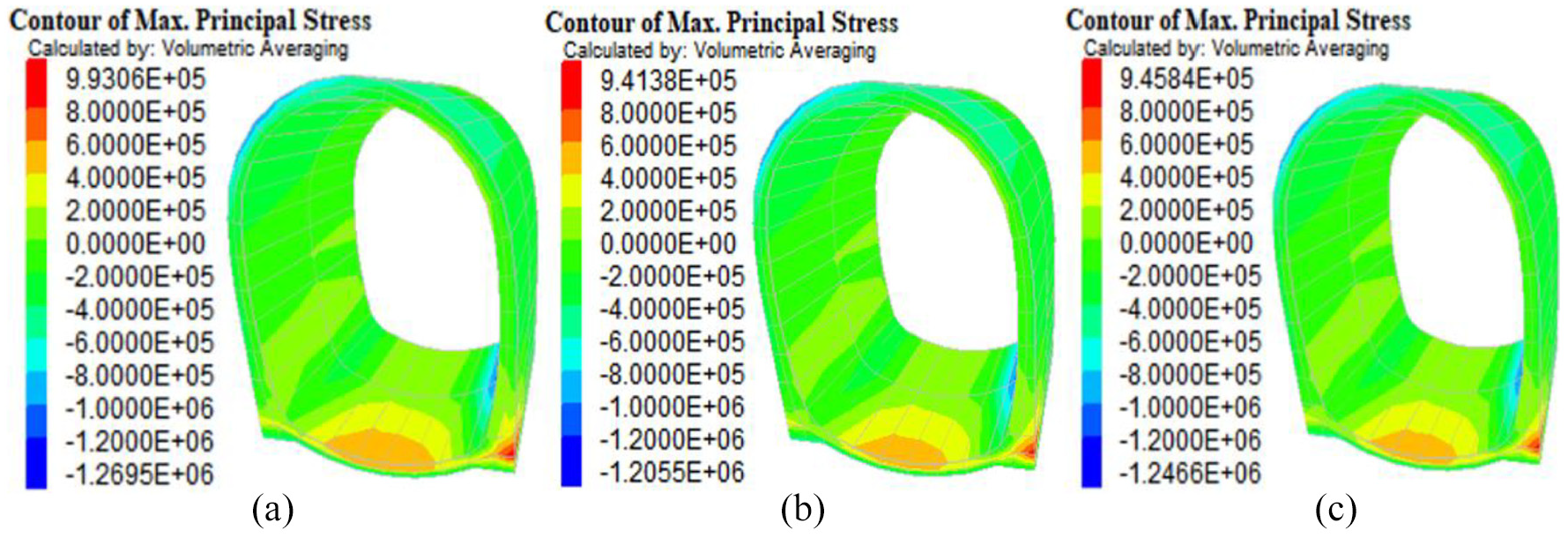
Maximum principal stress contour of secondary lining structure: (a) PC; (b) SFRC; and (c) SBHFRC.
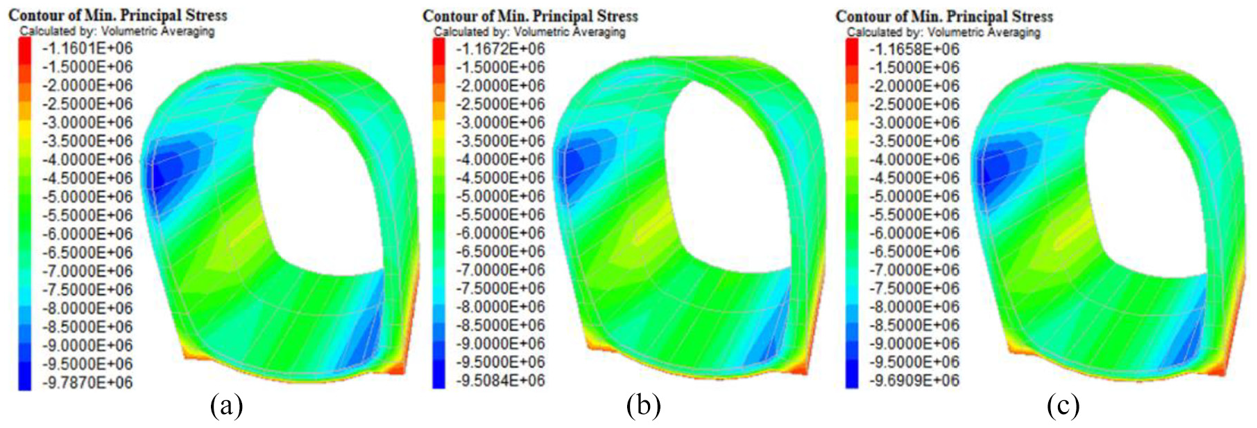
Minimum principal stress contour of secondary lining structure: (a) PC; (b) SFRC; and (c) SBHFRC.
According to the maximum principal stress of the secondary lining structure, the seismic effect of working conditions 2 and 3 was calculated (compared with working condition 1), as shown in Table 5. As can be seen from Table 5, the maximum and minimum principal stresses of PC lining are 0.99 and −9.79 MPa, respectively. After using FRC lining, the maximum and minimum principal stresses of the secondary lining structure decrease, and the maximum and minimum principal stresses of SFRC lining are 0.94 and −9.51 MPa, respectively. Comparing with PC, the maximum and minimum principal stresses of SBHFRC lining are 0.95 and −9.69 MPa, respectively, which are 4.73% and 1.02% less than PC. From the point of view of controlling the maximum and minimum principal stresses, the seismic effect of SFRC secondary lining is better than that of SBHFRC secondary lining.
Principal stress and seismic effect.
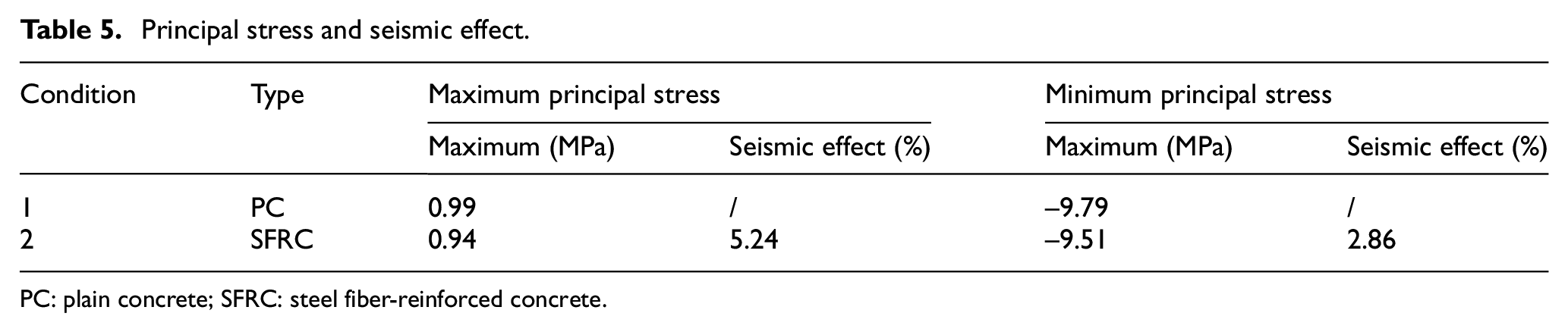
PC: plain concrete; SFRC: steel fiber-reinforced concrete.
Shear stress
The shear stress contour of tunnel structure in fault fracture zone under different working conditions was extracted, as shown in Figure 11.

Maximum shear stress contour of secondary lining structure: (a) PC; (b) SFRC; and (c) SBHFRC.
The maximum shear stress of the secondary lining structure was extracted, and the aseismic effect of working conditions 2 and 3 was calculated (compared with working condition 1), as shown in Table 6. From Table 6, it can be seen that the maximum shear stress of PC lining is 4.78 MPa. After using FRC lining, the shear stress of secondary lining structure decreases. The maximum shear stress of SFRC is 4.63 MPa, the seismic effect is 2.93%, and the maximum shear stress of SBHFRC is 4.73 MPa. The seismic effect was 1.05%. From the aspect of controlling shear stress, the seismic effect of SFRC secondary lining is better than that of SBHFRC secondary lining.
Maximum shear stress and seismic effect.

PC: plain concrete; SFRC: steel fiber-reinforced concrete.
Safety factor
The minimum safety factor, corresponding axial force, and bending moment (as shown in Figure 12) of the second lining of each monitoring section (in which sections S5 and S6 are the inner section of the fractured zone) under different working conditions were extracted, and the seismic performance of the second lining was calculated (as compared with that in case 1), which is shown in Table 7.

Each monitoring section: (a) moment; (b) axial force; and (c) minimum safety factor.
Minimum safety coefficient and seismic effect of monitoring section in fractured section.

PC: plain concrete; SFRC: steel fiber-reinforced concrete; SBHFRC: steel-basalt hybrid fiber-reinforced concrete.
The axial force, the bending moment, and the safety factor of secondary lining structure can be estimated by the following equations

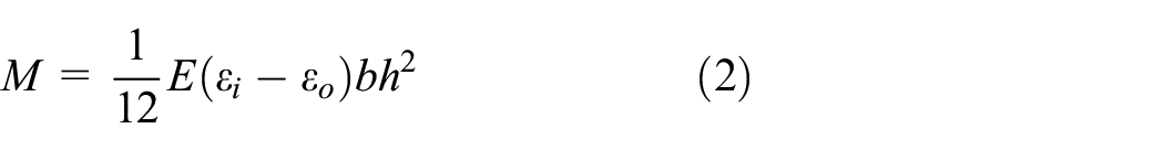


where N and M represent axial force and bending moment, respectively; b represents the width of cross section, where the adopted value was 1 m; h means section thickness; E represents modulus of elasticity. εi and εo represent the strain inside and outside of lining structure. Ra and Rl mean ultimate compressive and tensile strength of concrete, respectively; K represents safety factor. ϕ means the longitudinal bending coefficient of the component. α means the influence coefficient of the eccentricity of the axial force.
From Figure 12 and Table 7, it can be seen that the minimum safety factor of each section of SFRC and SBHFRC lining is larger than that of PC lining, and the minimum safety factor of SBHFRC lining is larger than that of SFRC lining. In the fault fractured section, the structural safety factor was increased by 32.99% using SFRC secondary lining and 36.08% using SBHFRC secondary lining. The seismic effect of SBHFRC secondary lining is better than that of SFRC secondary lining.
Conclusion
This article investigates the seismic performance of FRC tunnel lining by finite difference numerical calculation. The seismic displacement and stress response of PC, SFRC, and SBHFRC lining were comparatively analyzed. The safety coefficient and seismic effect of fractured section was obtained. On the basis of these analyses, the following relevant conclusions are drawn:
Under the seismic input of modified Wenchuan earthquake waves in three directions, using SFRC in the secondary lining structure can reduce the vertical displacement response of the tunnel across the fault fracture zone by 1.67%, using SBHFRC can reduce the vertical displacement 0.97%; using SFRC can reduce the transverse displacement by 0.68%, using SBHFRC can reduce the transverse displacement 0.39%; using SFRC can reduce the longitudinal displacement by 11.32%, using SBHFRC can reduce the longitudinal displacement 7.54%.
According to the change of the convergence of the side wall during the earthquake, the application of FRC can reduce the convergence of the side wall. The seismic effect of SFRC is 6.54%, and that of SBHFRC is 5.14%.
In the analysis of tunnel lining stress response, the maximum and minimum principal stresses of the tunnel across the fault fracture zone can be reduced by SFRC and SBHFRC. The maximum principal stresses can be reduced by 5.24%, 4.73%, and the minimum principal stresses can be reduced by 2.86% and 1.02%, respectively. The maximum shear stress can be reduced using FRC. The seismic effect of SFRC is 2.93%, and that of SBHFRC is 1.05%.
Structural safety factors were calculated by formulas in Code for Design of Road Tunnel, 25 the application of FRC can effectively increase the structural safety factor, in which the seismic effect of SFRC secondary lining is more than 32.99%, and that of SBHFRC secondary lining is more than 36.08%.
From the seismic displacement response and stress response, including the convergence of the side wall, the seismic effect of SFRC secondary lining is slightly better than that of SBHFRC secondary lining. Meanwhile, the seismic effect of SBHFRC secondary lining is better than that of SFRC secondary lining for safety factors. In any case, the FRC lining can improve the seismic response to the second lining, thus improving the seismic safety of the fault-crossing tunnel.
Footnotes
Handling Editor: James Baldwin
Author contributions
Zh.Ch. and L.M. under the guidance of D.A. and G.C. contributed to numerical model test; G.C. contributed to investigation; L.M. under the help of D.A. contributed to writing—original draft preparation; D.A. and Zh.Ch. contributed to writing—review and editing; and G.C. contributed to funding acquisition.
Declaration of conflicting interests
The author(s) declared no potential conflicts of interest with respect to the research, authorship, and/or publication of this article.
Funding
The author(s) disclosed receipt of the following financial support for the research, authorship, and/or publication of this article: The study was financially supported by the National Natural Science Foundation of China, grant number 51408008 and 51478277; the Youth Talent Support Program of Beijing, grant number 1759-004; the Basic Applied Study of Sichuan Province, grant number 2015JY0166; and the Youth Talent Program of North China University of Technology.