
Abstract
This article is aimed to investigate the shear resistance of the beams reinforced with fiber-reinforced polymer stirrups. Together with theoretical analysis of the existing shear resistance provisions in design codes and literature, an experimental research was performed. During the experimental investigation, four doubly reinforced rectangular concrete beams were designed, produced, and tested to failure. A new analytical calculation method (including, but not limited to statistical validation) to investigate the shear response of fiber-reinforced polymer–reinforced concrete beams has been developed. A database with 102 beams was compiled, in order to evaluate the guideline provisions and proposed analytical calculation method. The experimental results were compared with theoretical results obtained by the proposed analytical calculation method. Correlation between analytical and experimental results is more accurate than using the existing provisions in design codes and literature for fiber-reinforced polymer–reinforced concrete beams.
Keywords
Introduction
Concrete structural members are usually reinforced with non-prestressed steel reinforcement or prestressed steel tendons. These structural members are sufficiently durable because high alkalinity of concrete protects steel reinforcement from corrosion. However, there are vast structures, such as water treatment facilities, chemical storage tank systems, concrete bridges, and dock and pier structures, which are exposed to aggressive environment and where these structures are affected by deicing salts, humidity, and temperature. The aggressive conditions reduce alkalinity of concrete. It leads to corrosion of steel reinforcement. Also it is not advisable to use steel reinforcement in structures that are exposed to electromagnetic fields. Because of the reasons listed above, fiber-reinforced polymer (FRP) reinforcement, which consists of fibers impregnated in a resin matrix, could be a good replacement for steel reinforcement. Non-magnetic properties of FRP reinforcement, corrosive resistance and high tensile strength, allow it to be used as reinforcement for concrete structural members.1–6 Test results showed that non-metallic reinforcement can be used for structures such as reactor base mats, airport runway structures, and electronics laboratories or for the structures where medical equipment is stored. 7 Furthermore, often FRP materials are used for strengthening of concrete structures.8–13
The application of FRP materials in civil engineering is recognized worldwide. Various organizations in countries such as United States, 14 Canada, 15 Great Britain, 16 Japan, 4 and Italy 17 released design guidelines, recommendations, and standards, where FRP reinforcement is considered as the main reinforcement in concrete structural members.
FRP reinforcement can be used as longitudinal and shear reinforcement. Shear reinforcement is used when concrete shear capacity is exceeded. Usually, shear reinforcement is used as closed stirrups. However, manufacturing of these closed stirrups is not simple. FRP reinforcement can be bent when resin is not hardened yet or by heating already cured resin. Stirrup can be formed by heating a straight FRP bar and bending it into the desired shape. 18 Lees’ 19 experimental study of carbon, aramid, and glass fiber–reinforced polymer (GFRP) bars has shown that when ratio of bar’s radius and diameter is 3, 5, and 7, tensile strength of the corner of the bent stirrup is approximately 45%, 55%, and 65% of the straight bar’s tensile strength. However, it is noted that these results depend on the type of the fiber and resin, as well as on the method of forming the stirrup. 4 It was found that in order to achieve 50% of the straight bar’s tensile strength in the corner of the bent stirrup, ratio of GFRP bar’s radius and diameter has to be 4, while the ratio of carbon fiber–reinforced polymer (CFRP) bar’s radius and diameter has to be 7. 20
When separate straight FRP bars are used for shear reinforcement in concrete beams, anchorage of these straight FRP bars becomes an issue. Efficiency of anchorage directly depends on FRP bar’s surface roughness. FRP bar’s surface roughness depends on reinforcement’s manufacturing method. Physical properties of FRP bar’s surface determine the bond strength between reinforcement and concrete.
Comparing two beams reinforced with the same amount of reinforcement, one with steel reinforcement and another with FRP reinforcement, in latter beam, the depth of the compression zone after cracking is smaller due to smaller modulus of elasticity of FRP reinforcement. 21 Section’s depth of the compression zone is smaller and crack widths are larger. Because of the reasons mentioned above and due to aggregate interlock, shear transfer in the compression zone and across cracks decreases. Regarding the results of experimental studies, where concrete beams without shear reinforcement were tested, it was stipulated that shear resistance depends on the area of longitudinal reinforcement and modulus of elasticity.
Current shear resistance design recommendations
Most of the available calculation models for shear resistance of concrete beams reinforced with FRP reinforcement are based on methods and assumptions, which are applied to evaluate the shear resistance for beams reinforced with steel. In addition to this, the current methods are based on a theory that shear capacity of reinforced concrete beam consists of concrete shear resistance Vc and FRP transverse reinforcement shear resistance Vf 21–25 Likewise, one of the main assumptions of this theory introduces mechanisms, which transfer shear stresses, are plastic and redistribution of stresses can occur. However, FRP reinforcement is an elastic and brittle reinforcement, which is not characterized by plastic behavior. Consequently, the question is whether calculation models aimed for calculation of shear capacity for steel-reinforced elements can be used for the design of FRP-reinforced beams. 26
The results of experimental investigations, carried out by various authors,27–35 show that shear capacity of concrete beams reinforced with longitudinal and transverse FRP reinforcement can be verified with sufficient margin by applying classical methods, which are mainly used for the design of beams reinforced with conventional reinforcement. However, it is therefore highly recommended to limit the maximum strain in FRP shear reinforcement. This restriction is applied in separate design guidelines or recommendations as per American Concrete Institute (ACI) 440.1R-06 or Japan Society of Civil Engineers (JSCE).
First, the limit of maximum strain was set to 0.002–0.0025, by analogy to the yielding strain of steel. After more experiments were performed, it was suggested that the limit value could be higher. In order to use all advantages of FRP reinforcement, these higher values are used in many design recommendations currently.
ACI 440.1R-06 and JSCE design recommendations
According to ACI 440.1R-06 and JSCE design recommendations, the shear capacity of FRP-reinforced concrete beam can be estimated using the following equation

where Vc is the concrete shear resistance; Vf is the FRP transverse reinforcement shear resistance.
Concrete shear resistance, according to ACI 440.1R-06


where c is the depth of compression zone at cracked transformed section; k is the coefficient, which accounts the decreasing depth of neutral axis.
Concrete shear capacity according to JSCE could be calculated as follows


where βd is the coefficient, by which the size effect is estimated; βp is the coefficient, which accounts the specific properties of FRP reinforcement.
Shear capacity provided by FRP shear reinforcement, according to ACI 440.1R-06, can be calculated using the following equation

where ffw is the stress level in the FRP shear reinforcement at the ultimate state.
The stress level in the FRP stirrups ffw is limited, in order to limit shear crack width and to avoid rupture of FRP stirrup in the bent portion of the bar

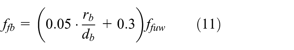
where ffb is the tensile strength of FRP bent bar; rb is the bending radius of FRP bar; db is the diameter of the FRP bar in the bent portion; ffuw is the tensile strength of FRP shear reinforcement.
JSCE recommends calculating shear resistance of FRP shear reinforcement using this equation


where εfw is the strain in the FRP stirrup at the ultimate state; z is the lever arm of internal forces.
According to JSCE design recommendations, the stress level in the FRP stirrups is also limited

where εfw is calculated according to equation (13) and ffb is calculated according to equation (11).
Eurocode 2 design recommendations
This method originally was developed for evaluation of shear capacity for steel-reinforced concrete beams. 36 The Eurocode 2 (EC 2) proposes method that is based on a truss model.
According to EC 2, shear resistance for concrete beams reinforced with transverse reinforcement


where Vu,f is the value of the shear force which can be resisted by the shear reinforcement; Vu ,max is the value of the maximum shear force which can be sustained by the member, limited by crushing of the compression struts; θ is the angle between the concrete compression strut and the beam axis perpendicular to the shear force; αcw is the coefficient taking into account the state of the stress in the compression chord; ν 1 is the strength reduction factor for concrete cracked in shear.
The recommended limiting values for ctgθ

This restriction means that the angle between the concrete compression strut and the beam axis cannot be less than 21.8° and more than 45°.
Sato et al. shear resisting model
This shear resisting model was developed by the numerical study using nonlinear finite element program. 37 It is assumed that shear capacity of the cracked section can be evaluated using this equation

where Vstr is the shear resisting force by other than transverse reinforcement at the shear cracking zone.
Furthermore, it was found that the largest shear capacity of the beam is at the section where its neutral axis intersects with the straight line, which connects the loading and supporting points. It is assumed in this model that the examined section consists of concrete compression zone at the loading point, shear crack zone, where section’s shear resistance is the largest and horizontal zone, which connects compression and shear cracking zones (Figure 1). These assumptions can be written as


Shear resisting model and distribution of shear resisting stresses.
where Vcom is the shear resisting force by concrete at the horizontal zone, which connects compression and shear cracking zones; α is the angle of the principal stress at the compression zone; β is the angle of the principal stress at the horizontal zone.
Proposed shear design model
Proposed shear design model is also based on the assumption that shear strength consists of concrete shear capacity as well as FRP transverse reinforcement shear capacity. However, these two components can be evaluated differently from previously reviewed design provisions.
In the proposed model, shear resistance is calculated according to equation (1).
It is known that the resultant shear force of shear stresses caused at cross section can be calculated
where
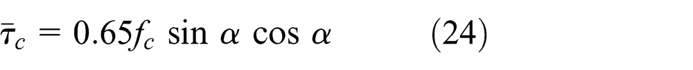
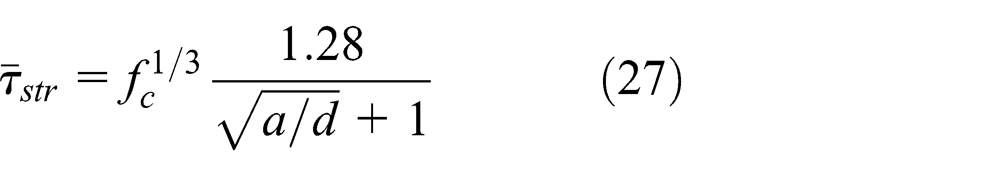
It is known that the limiting values of average shear stresses are approximately equal to

It is also known that shear cracking angle for reinforced concrete beam may vary from 26° to 45°. Assuming that shear cracking angle is equal to 45° and taking into account equation (29), concrete shear resistance can be calculated
Reinforced concrete experimental studies have shown that when shear cracking angle is less than 45°, concrete shear resistance decreases. The influence of shear cracking angle on concrete shear resistance Vc can be evaluated using ratio of shear span a and effective depth d. In that case, concrete shear resistance of concrete beams without shear reinforcement can be calculated

The influence of FRP flexural reinforcement for the concrete shear resistance Vc is evaluated using coefficient φf . Therefore, the following equation is proposed for calculating concrete shear capacity of concrete beams reinforced with FRP flexural reinforcement
Coefficient φf , which estimates the specific flexural FRP reinforcement’s properties, is determined by analyzing the results of experimental tests, which are given in section “Review of the existing experimental tests”
where Eflex. is the modulus of elasticity of flexural reinforcement; ρflex. is the flexural reinforcement ratio.
Research shows that when shear span a increases, concrete shear resistance Vc decreases significantly. In the case of high shear span a values, experimental concrete shear resistance significantly differs from the calculated strength. Taking that into account, the maximum value of shear span a is limited

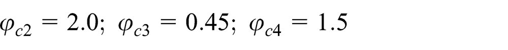
Coefficients φc 2, φc 3, and φc 4, which estimate concrete’s properties, are proposed as follows:
For normal weight concrete
FRP transverse reinforcement shear capacity Vf is determined by summing up multiplied values of FRP shear reinforcement area Afw and tensile strength ffw

where Afwi is the area of one FRP reinforcement bar; n is the number of transverse reinforcement bars in the shear cracking zone.
Critical projection of shear cracking zone, where FRP shear reinforcement contributes to shear strength of concrete beam, is indicated as a 0 (Figure 2).

Shear resisting model.
Shear strength caused by web reinforcement in the structural member’s linear meter

FRP transverse reinforcement shear capacity can be expressed by the following equation

In order to calculate critical projection a 0, the following assumptions are accepted

Therefore, the following expression can be written

From equation (40), critical projection a 0
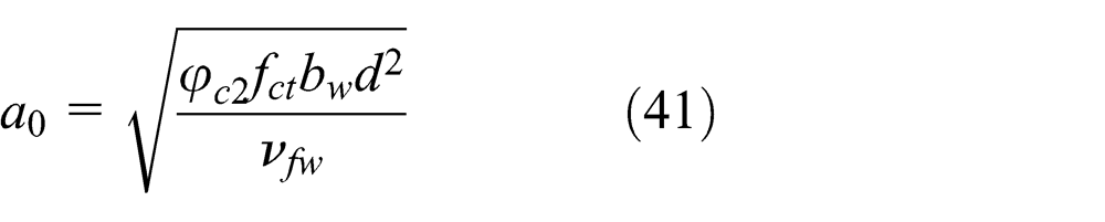
As previously mentioned, shear cracking angle may vary from 26° to 45°. Also, critical projection a 0 always has to be smaller than shear span a, because web reinforcement does not transfer shear stresses uniformly along beam’s axis. Because of these reasons, critical projection a 0 is limited
The stress level in the FRP stirrups ffw is determined by the following equation

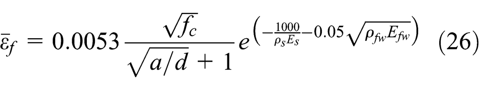
The maximum strain in the FRP stirrup is determined by analyzing experimental data, which were compiled from tests performed by the authors of this article and other researchers. The maximum strain is suggested as follows:
For beams reinforced with flexural steel reinforcement and shear FRP reinforcement

For beams reinforced with both flexural and shear FRP reinforcement

The maximum strain in the FRP stirrups is limited in order to control shear crack width.
Experimental study
Experimental study by authors
Materials and specimens
In this study, experimental tests of concrete beams, reinforced with flexural steel reinforcement and straight GFRP bars as shear reinforcement, were carried out. The mechanical properties of concrete and GFRP reinforcement were determined experimentally. The compressive strength, tensile strength, and modulus of elasticity of the concrete were evaluated by testing standard cubes, standard cylinders, and standard prisms, which were cast at the same time and cured under the same conditions as the test specimens. Dimensions of standard cubes were 150 × 150 × 150 mm, standard cylinders 150 × 300 mm, standard prisms 100 × 100 × 400 mm. Six cubes and three cylinders were tested according to the requirements of EN 12390-3:2009. The mean value obtained for the cube compressive strength was 36.3 N/mm2. The mean cylinder compressive strength and modulus of elasticity were determined from the results of cylinder testing. The mean cylinder compressive strength was 29.0 N/mm2. The mean value obtained for the modulus of elasticity was 26.5 × 10³ N/mm2. The mean tensile strength was determined by testing prisms according to the requirements of EN 12390-5:2003. The mean value obtained for the tensile strength was 3.34 N/mm2.
The characteristic yield strength of the steel bars used to reinforce beams was 500 N/mm2. The GFRP bars used to reinforce beams in shear were produced by Schock ComBAR. The mechanical properties of GFRP bars were determined by direct tension test (Figure 3). Bars were tested according to the requirements of ISO 10406-1. Four GFRP bars were tested. The mean value obtained for the tensile strength of GFRP bar was 1418.2 N/mm2, the mean value obtained for the elastic modulus was 6.2 × 10³ N/mm2, and the ultimate strain was 2.36%.

Testing of the GFRP reinforcement bar.
Four doubly reinforced rectangular concrete beams were constructed for experimental testing. Beams were reinforced with four 14-mm-diameter steel bars (As = 616 mm2) in the tension zone and with two 6-mm diameter steel bars (As = 57 mm2) in the compression zone of the beam.
The carried out tests38,39 showed that tensile strength of FRP bar was significantly reduced because of tensile and shear stresses acting together. The test results showed that failure of the FRP stirrups occurs in the corner of the bent stirrup. Because of the aforesaid, through experimental program, the objective was to investigate the influence of straight FRP bars, used as shear reinforcement, for shear strength of the specimens. Therefore, specimens of this experimental study were reinforced with straight FRP shear reinforcement bars. The beams were reinforced with 8-mm-diameter GFRP bars, and the spacing of the bars was 150 mm. The details of the test beams are illustrated in Figure 4. The cages of reinforcement in the formwork of the beams are shown in Figure 5.

Details of test beams.

Reinforcement cages in the formwork of the beams.
Experimental setup and instrumentation
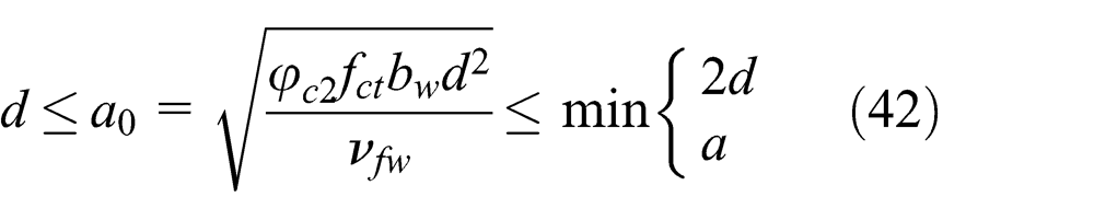
In this experimental study, reinforced concrete beams were subjected to three-point bending. The loading point was 350 mm away from support (Figure 6). Strains were measured by inductive sensors attached on the surface of the specimens. The layout of inductive sensors is shown in Figure 6. Concrete strains were measured by the inductive sensors in the compression and tension zones of the specimens, as well as in the shear cracking zone. Crack widths were monitored by optical microscope with an accuracy of 0.05 mm. During the test, load was applied in increments of 10 kN. After every increment, crack widths were measured. Crack widths were measured until applied load was about 60% of estimated theoretical shear strength of the specimen.
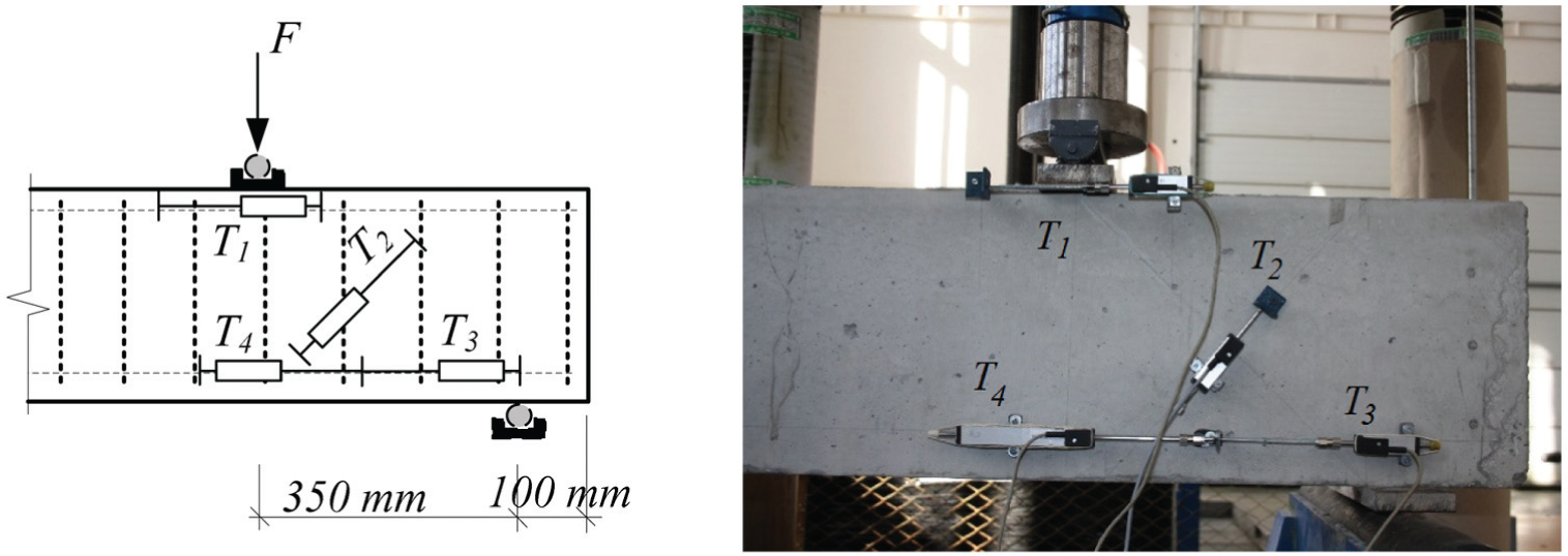
Test arrangement.
Test results
The specimens of this experimental study (S-3-A, S-4-A, S-3-B, S-4-B) were subjected to one concentrated load (Figure 6). During experimental work, the objective was to obtain shear strength, strains in the concrete, and failure mode for all concrete beams. The shear failure was observed for all tested beams. The failure and crack opening modes (Figure 7) were very similar for all specimens, because of same geometrical properties as well as the amount of reinforcement.

Cracking pattern at failure for the test specimens
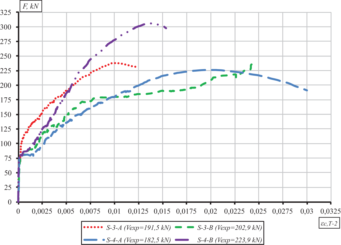
The experimental shear strength for beam S-3-B was Vexp = 202.9 kN, for S-4-B was Vexp = 223.9 kN, for S-3-A was Vexp = 191.5 kN, and for beam S-4-A was Vexp = 182.5 kN. The test results show that out of four reviewed calculation models, only shear strength values obtained by Sato et al. and JSCE methods are smaller than the experimental results (Vcalc,Sato = 134.2 kN, Vcalc,JSCE = 59.5 kN). The shear strength values obtained by EC 2 and ACI 440.1R-06 equations were larger than the experimental shear strength values (Vcalc,EC = 271.3 kN, Vcalc,ACI = 270.7 kN). Tensile strength of the GFRP shear reinforcement bars was not limited using EC 2 and ACI 440.1R-06 calculation methods. Straight GFRP bars were used as shear reinforcement; therefore, tensile strength did not decrease because of bending of the bar. Tensile stress level in the shear reinforcement depends on the calculated strain, when calculations are made using Sato et al. and JSCE design recommendations. Due to lower tensile strength of the bar, the calculated theoretical shear strength was lower than experimental.
During the testing in all the tested beams, the vertical crack in the tension zone of the beam under the loading point opened first. First, vertical crack opened up in beam S-3-A, when applied load was F = 39.5 kN (stress in the tensile concrete zone was σct = 4.95 N/mm2), in beam S-4-A was F = 50.0 kN (σct = 6.27 N/mm2), in S-3-B was F = 40.0 kN (σ ct = 4.55 N/mm2), and in S-4-B was F = 50.0 kN (σ ct = 5.69 N/mm2). In all these cases, concrete stresses in the tension zone of the beam exceeded the mean concrete tensile strength value (fctm = 3.34 N/mm2), when first vertical crack opened up. Load–strain (measured by T4 inductive sensor) responses for tested beams are shown in Figure 8. It can be seen from this graph how concrete strains change after opening of the first vertical crack. The first vertical crack is shown in Figure 7. The width of this crack gradually increased until applied load was about 30% of the calculated shear strength.
The first shear cracks formed when applied load was increased. At the same time, the first shear crack in beam S-3-A formed, when applied load was 27.8% of the calculated shear strength (F = 66.1 kN), in beam S-4-A 34.6% (F = 78.3 kN), S-3-B 27.9% (F = 77.4 kN), and S-4-B 23.9% (F = 73.1 kN). In general, shear cracks formed when maximum tensile stresses, which depend on specimen’s geometrical properties and applied loads, were developed. It should be said that mechanical properties of shear reinforcement do not influence the quantity of these stresses. The obtained results were very similar because of the same properties of the specimens.

Load–strain (measured by T4 inductive sensor) relationships of tested beams.
When first shear crack was formed, the value of the load was determined based on load–strain (measured by T2 inductive sensor) relationships shown in Figure 9. In order to determine the moment of the shear crack formation as accurately as possible and its further development, concrete strains regarding shear cracking zone were measured by inductive sensor T2.
Load–strain (measured by T2 inductive sensor) relationships of tested beams.
It can be seen from this graph that concrete strains increase linearly with increasing load until first shear crack forms. After the formation of first shear cracks, concrete strains increase nonlinearly. Moreover, shear cracks develop in the direction of maximum compressive stresses, and this direction changes in each case—that is why graphs in Figure 9 are different. Furthermore, after formation of shear cracks, GFRP shear reinforcement restrains the growth of shear cracks. Therefore, concrete strains are also related to quality of anchorage of shear reinforcement.
Review of the existing experimental tests
From reliability point of view, to verify proposed shear design model and to compare current available calculation models, test results of 102 concrete beams, reinforced with FRP shear reinforcement, were collected. The analysis showed that beams, reinforced with FRP shear reinforcement, can be reinforced with flexural steel or non-metallic reinforcement.
The collected database included 27 beams, reinforced with flexural steel reinforcement and FRP shear reinforcement (Table 1).40–44 This database consists of concrete beams with different geometrical properties, concrete mechanical properties, and different types and amounts of reinforcement.
Details of beams, reinforced with flexural steel reinforcement and FRP shear reinforcement.
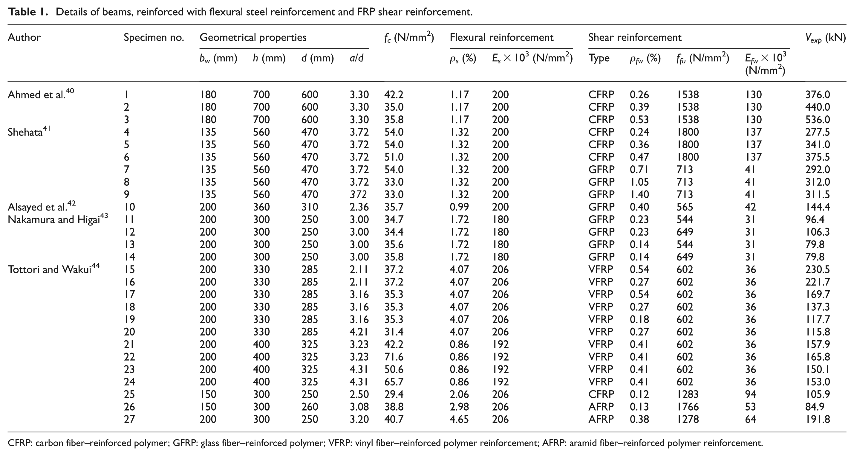
CFRP: carbon fiber–reinforced polymer; GFRP: glass fiber–reinforced polymer; VFRP: vinyl fiber–reinforced polymer reinforcement; AFRP: aramid fiber–reinforced polymer reinforcement.
The collected database also included 75 beams, reinforced with both flexural and shear FRP reinforcement.20,27,43–48 The details of the beams are shown in Table 2.
Details of beams, reinforced with flexural FRP reinforcement and FRP shear reinforcement.

CFRP: carbon fiber–reinforced polymer; AFRP: aramid fiber–reinforced polymer reinforcement; GFRP: glass fiber–reinforced polymer.
Verification of the proposed shear design model
In order to verify the proposed shear design model, comparison of experimental and theoretical shear strength values, calculated using reviewed and proposed calculation methods, was performed. The four specimens, tested by the authors of this article, were also included in the analysis. The results of this analysis are shown in Figures 10–12 and are discussed further in this article.

Vexp /Vcalc values obtained by the proposed shear design model for beams reinforced with flexural steel and FRP shear reinforcement.

Vexp /Vcalc values obtained by the proposed shear design model for beams reinforced with both flexural and shear FRP reinforcement.

Vexp /Vcalc values obtained by the proposed shear design model for beams reinforced with flexural steel or FRP reinforcement and FRP shear reinforcement.
It can be seen from Figure 12 that for the proposed shear design model, the average value of Vexp /Vcalc is 1.02 with standard deviation of 0.25 and coefficient of variation of 24.2%. According to these results, systematic error is 0.02 and random error is equal to 0.25 for the proposed calculation method for beams, reinforced with FRP shear reinforcement.
It should be noted that the compiled database included specimens with very different geometrical characteristics (width of the web varies from 135 to 450 mm, effective depth varies from 250 to 600 mm), reinforced with different types of FRP reinforcement (aramid fiber–reinforced polymer reinforcement (AFRP), GFRP, CFRP, vinyl fiber–reinforced polymer reinforcement (VFRP)) and steel reinforcement, and with different amounts of reinforcement (longitudinal reinforcement ratio varies from 0.53% to 4.65%, transverse reinforcement ratio varies from 0.04% to 1.50%). All these variables influence standard deviation and coefficient of variation of the proposed model.
It can be seen from Figures 10 and 12 that the biggest difference between theoretical calculations and experimental results of shear strength is for specimens, tested by the authors. As already discussed above, straight GFRP bars were used as shear reinforcement in the experimental study, performed by the authors, while other specimens were reinforced with FRP stirrups. In order to draw conclusions about the calculation of shear resistance for beams reinforced with straight FRP bars, more experimental studies have to be performed.
Theoretical shear resistance was calculated for all specimens from the compiled database (Tables 1 and 2), using ACI 440.1R-06, JSCE, EC 2, and Sato et al. design recommendations also. The performed analysis of the current available design guidelines, recommendations, and shear strength of beams reinforced with FRP reinforcement has shown that there is no universal calculation method to correctly evaluate maximum strain in the FRP shear reinforcement, which may affect the shear strength of concrete beams. The maximum strain in shear reinforcement is taken as 0.004 in EC 2 and ACI 440.1R-06 design recommendations, and the maximum strain is calculated using empirical equations as per JSCE, Sato et al. design recommendations and in the shear design model proposed by the authors of this article.
Table 3 gives the results of average Vexp /Vcalc value, standard deviation, and coefficient of variation for all reviewed design recommendations and for proposed design model. The performance of the design equations was evaluated using the collected database for beams reinforced with flexural steel and FRP reinforcement and FRP shear reinforcement.
The comparison of experimental and calculated shear strength for beams reinforced with flexural steel or FRP reinforcement and with FRP stirrups.

FRP: fiber-reinforced polymer; ACI: American Concrete Institute; JSCE: Japan Society of Civil Engineers.
Table 3 shows that the most accurate method with the least scattered values is the proposed shear design model as the average Vexp /Vcalc is 1.02 with a coefficient of variation of 24.1%.
Conclusion
This article has presented a comparative investigation regarding the shear resistance of FRP-reinforced concrete beams. The following conclusions can be drawn:
The analysis of available shear strength calculation methods showed that there is no universal calculation model for calculating shear strength of concrete beams reinforced with FRP reinforcement. The available design recommendations are based on methods, which are intended for calculating shear resistance of steel-reinforced concrete beams. Therefore, these models do not properly take into account specific properties of FRP reinforcement. Design models have to be modified using empirical equations, which could more accurately estimate the influence of the specific FRP properties.
The results of the experimental tests of concrete beams reinforced with straight FRP shear stirrups showed that the anchorage is the main concern, when using non-metallic shear reinforcement. If straight FRP bars are used, they have to be securely fixed to the longitudinal reinforcement.
Through comparative analysis of investigated design models, it was found that the most accurate model is the shear design model, proposed by the authors (Vexp /Vcalc = 1.02, σx = 0.25, ν = 24.1%). The analytical values based on the proposed method are in good agreement with the experimental results. The suggested model is intended for calculating shear strength of concrete beams reinforced with FRP shear reinforcement. This model evaluates the influence of different types of FRP reinforcement for shear strength. The proposed equations allow to evaluate maximum strain of FRP shear reinforcement in order to control shear crack width.
Footnotes
Appendix 1
Academic Editor: Yu-Fei Wu
Declaration of conflicting interests
The authors declare that there is no conflict of interests regarding the publication of this article.
Funding
This research received no specific grant from any funding agency in the public, commercial, or not-for-profit sectors.