
Abstract
Rail grinding profile prediction in different grinding patterns is important to improve the grinding quality for the rail grinding operation site. However, because of high-dimensional and strong nonlinearity between grinding amount and grinding parameters, the prediction error and computational cost is relatively high. As a result, the accuracy and efficiency of conventional methods cannot be guaranteed. In this article, an accurate and efficient rail grinding profile prediction method is proposed, in which an interval segmentation approach is proposed to improve the prediction efficiency based on the geometric characteristic of a rail profile. Then, the accurate area integral approach with cubic NURBS is used as the grinding area calculation approach to improve the prediction accuracy. Finally, the normal length index is introduced to evaluate the prediction accuracy. The accuracy and stability of the proposed method are verified by comparing a conventional approach based on a practical experiment. The results demonstrate that the proposed method can predict the rail grinding profile in any grinding pattern with high accuracy and efficiency. Meanwhile, its prediction stability basically agrees with the conventional approach.
Introduction
Rail grinding is an effective method of removing rail defects to guarantee the shape of the rail profile, and the rail service life can be prolonged too. 1 It is mainly a maintenance method for the in-service rail at present, and it becomes an important approach to ensure the sustainable development of rail transit. In practical grinding operation, rail grinding profile prediction in different grinding patterns is an important method to improve the grinding quality at the rail grinding operation site. 2 However, because of the high-dimensional and strong nonlinearity between grinding amount and grinding parameters, the prediction error and computational cost are relatively high. 3 As a result, the accuracy and efficiency of current methods cannot be guaranteed. Therefore, it is necessary to reduce the prediction error and computational cost with a proper approach during the rail grinding profile prediction. Then the rail grinding quality could be improved, and the rail service life for high-speed railways can be prolonged too.
At present, the researches on rail grinding are mainly focused on two aspects, including the target profile optimization and the rail grinding mechanism.4,5 Thereinto, the purpose of the target profile optimization is to improve the wheel/rail (w/r) contact performance, and provide a goal for the practical grinding operation. That means it solves the “What is the goal?” problem for rail grinding. There have been a number of studies on this aspect, taking the w/r contact performance6,7 or rail’s service life as the optimization objective, 8 using different optimization algorithms to obtain the optimal grinding profile based on w/r contact theory. For instance, in order to improve the w/r contact performance and the curve negotiation ability, Zeng et al.2,9 proposed a new optimization method based on the Kriging surrogate model and the genetic algorithm to optimize the target profiles of the asymmetrical rail grinding in sharp-radius curves and the rail grinding in straight line for high-speed railway. Xiao and Liu 10 regarded the railhead silhouettes in differential rail cants as the rail grinding target profiles and obtained an optimal rail grinding target profile, while the equivalent conicity, contact stress, and grinding amount were taken as the evaluation indices. In order to determine the optimal design of the target profile for a curved segment, Wang et al. 11 proposed an optimization method that regards the minimum average metal loss in terms of wear and grinding for the whole design cycle as the design objective. To improve the match of rail profiles and different kinds of wheel profiles, Xu et al. 12 designed an optimal target profile based on w/r contact theory and vehicle dynamics theory considering the diversity of wheel profiles on the w/r contact performance in the same railway line. The results indicated that the designed target profile not only improves the w/r contact performance and vehicle travel stability, but also reduces the wheel wear. The primary difference between the above researches is that the selected optimization objective is different, then the established optimization model is different, and naturally the obtained final optimal target profile is different. The w/r contact performance is the fundamental optimization objective for most of the researches, w/r wear, and vehicle travel stability in some special railway sections are often regarded as additional optimization objectives to construct a multi-objective optimization model to obtain the optimal target profile.
The research purpose of the grinding mechanism is to analysis the material removal during the rail grinding process, providing a basis for the grinding pattern design, and ensuring the final obtained profile after grinding operation is consistent with the designed target profile. That means it solves the “How to do?” problem for rail grinding operation. Zhi et al. 13 established a cutting force model related to the grain geometry, involving grain numbers, location of grains, and their cutting depth based on the micro-mechanism of the grinding process. Liu et al. 14 constructed a grinding ability model taking the sectional area of the removed metal as the evaluation index, and proposed an algorithm that generates personalized grinding patterns to arrange the grinding wheel location and proper sequence. Zhi et al. developed a mathematical model for the standard profile and built a traversal-sectional area and cutting length model for the ground rail by combining the characteristics of pattern-distributing and the interference relationship between the grinding stone and the rail head. Then the effects of different patterns on the actual profile and the theoretical profile were analyzed, including both of the symmetric patterns and the non-symmetric patterns. 15 These researches focus on the optimization method of grinding patterns and some fundamental grinding mechanisms. It is important for the grinding patterns design and for improvement of the grinding precision in practical operation. However, workers at the operation site often need a more intuitive method to predict the final-obtained grinding profile after adjusting the grinding parameters, to check whether the final-obtained profile is consistent with the target profile. It will be very useful to improve the work flexibility and efficiency for the practical grinding operation. Therefore, Zeng et al. proposed a prediction method of the rail grinding profile combined with NURBS curve and Kriging surrogate model (N-KG). The ultimate grinding profile in any grinding pattern could be predicted accurately after the prediction model is established based on the experimental data. 3
Previous researches mainly focus on the design of the target profile and the grinding patterns, as well as the fundamental grinding mechanism. It is important to improve the grinding precision and efficiency for rail grinding. Furthermore, there are few researches on the practical grinding process at the operation site. For instance, the grinding patterns are usually generated by the above methods based on the designed grinding target profile and the wear status of the on-site rail. But the final actual profile obtained after grinding operation using the generated grinding patterns, is not fully consistent with the designed target profile in some special situations, especially in the railway lines where the curvature of the rail profile changed rapidly. Operators need to adjust the grinding parameters to construct a personalized grinding pattern based on their own experience in these special situations, to obtain a satisfactory grinding profile at last. It means that the rail grinding quality is totally affected by the experience level of the operators, and the robustness of the grinding quality will be limited to some extent in this special situation. Zeng and colleagues 3 proposed the N-KG method to predict the grinding profile in any grinding pattern, and its precision is relatively high, but it has a shortcoming of long calculation time, and the efficiency is too low for practical grinding operation because the reserved maintenance time is usually limited. Therefore, to improve the prediction efficiency, this article proposed a novel prediction method for rail grinding profile based on an interval segmentation approach and accurate area integral with cubic NURBS (IS-AIN).
Overview of rail grinding: sequential forming mechanism and grinding patterns
Rail manufacturing defects and the wear generated in its service life will cause track geometry irregularity, then the w/r contact performance will deteriorate rapidly. Rail grinding is mainly a method to eliminate the problem in the existing railway line currently. The forming mechanism of the grinding profile could be described in Figure 1 based on the operating principle of a grinding train. A set of high-speed rotating grinding stones (e.g. the number of grinding stones is 96 for the GMC-96x grinding train) distributed in different angles are arranged above the rail surface, and the end surface of every stone grinds the rail profile sequentially, then the designed target profile is obtained at last. This kind of work principle is often called sequential forming mechanism. It could be described using the formula as shown in equation (1)
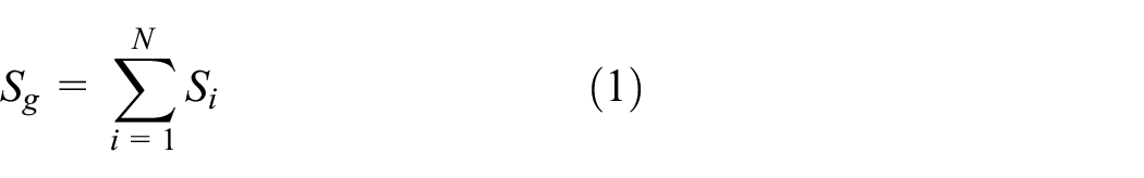
where Sg is the total sectional area of the rail profile that grinded by grinding stones, Si is the grinding area of ith grinding stone, and N is the number of grinding stones.

Sequential forming mechanism of rail grinding.
The grinding parameters, including the travel speed of the grinding train v, the deflection angle of a grinding stone θ, and the power of the motor driving the grinding stone P, are adjusted based on the designed target profile and the actual wear or damage situation of the rail profile during grinding operation. Every grinding stone has its own grinding parameters (vi, θi, Pi) in practical operation, and all the grinding parameters for every grinding stone are combined to constitute a parameter set, which is called grinding patterns. In the practical grinding operation, the general grinding patterns often designed using the integrated computation program in the grinding train or the operators’ experience based on the designed target profile.
Problem statement
To predict the grinding profile in different grinding patterns, the cross-sectional areas removed by the grinding stones need to be calculated. Thus, the core of the grinding profile prediction lies in the establishment of the quantitative relations between the grinding amount of a single grinding stone and the grinding parameters, according to the sequential forming mechanism of the rail grinding profile. 16 Therefore, most existing works pay more attention to the relevant relationship theory research between the grinding amount (e.g. grinding area, grinding depth) and the grinding parameters from the view of the micro-mechanism of the grinding process. Then, a prediction model of the grinding amount is constructed, and the prediction of the final profile based on the sequential forming mechanism is realized. However, the actual factors that affect the grinding process are not static during the practical operation, sometimes the type and range of the factors often go beyond the set scope. For example, the factors such as the climate at the construction site and the contamination situation of the rail surface cannot be considered in the theoretical analysis, while they obviously affect the grinding amount in the practical grinding operation. 17 For this reason, Zeng et al. established the Kriging (KG) model of grinding amount (grinding area) of a single grinding stone in different grinding parameters based on the field experimental data. On this basis, a prediction method of grinding profile is proposed using an accurate area integral with cubic NURBS. However, the grinding profile contains multiple circular curves with different radii in the whole grinding region. Taking the Chinese standard 60 kg/m as an example, the profile consists of five circular curves with different radii, and the angle range of the working tread covers from 60° to −20° for one-side track. It means that the deflection angle of the grinding stones should cover the whole range, and the value of the grinding amount will fluctuate rapidly with the change in the grinding angle during the establishment of the grinding amount prediction model. This will lead to a strong nonlinear characteristic relationship between the grinding amount and grinding parameters, which results in a decline in the prediction accuracy for the established prediction model, thereby certainly reducing the prediction precision of the final grinding profile. Therefore, the KG model is used to fit the relationship between the grinding area and grinding parameters based on its good ability in nonlinear function estimation in the literature by Yang et al. 3 However, KG model is a kind of interpolation model with unbiased estimation, the computational cost is relatively high, particularly the variable dimension greater than or equal to three, the computational cost increases significantly, 18 which after prediction will increase the computation time of completion to nearly 50 min. For the practical grinding operation, the computation time is too long. Consequently, reducing the computational cost and improving the prediction accuracy become necessary for the practical grinding operation.
Principle of the IS-AIN method
Quantitative relations between grinding amount and grinding parameters for one single grinding stone
The grinding process of a grinding train could be converted to a grinding stone that grinds the rail profile sequentially in different deflection angles according to the sequentially forming mechanism. Therefore, it is the first step to construct the quantitative relations between the grinding amount and the grinding parameters of one single grinding stone for the rail grinding profile prediction. The rail grinding process is a kind of metal removal process; essentially, the volume of the removed metal is the grinding amount, and the energy consumption of removing every unit volume is the grinding ratio energy. 19 According to the definition of the ratio energy and the researches on the microscopic mechanism of the rail grinding process, the relation between the removed metal volume and the travel speed v and the grinding power P is illustrated in equation (2)

where u is the ratio energy, Q is the energy consumption of a single grinding stone during the whole grinding process, Vg is the removed metal volume of a single grinding stone, d is the diameter of a grinding stone, Vl is the linear velocity of a grinding stone, P is the grinding power, v is the travel speed of a grinding train, K is a coefficient that is related to the grinding stone type, deflection angle θ, rail material, grinding environment condition, and so on.
The grinding area of a grinding stone in the rail cross section is a constant when the grinding time is short enough. It means that the grinding amount Vg could be expressed using the grinding area S of the grinding stone in the rail cross section when v and P are constant, and the grinding time t is short enough. Hence, it could be presented using equation (3)

The energy consumption Q of the grinding stone during the whole process is

According to equations (2)–(4), u could be described using equation (5)

Then, the quantitative relation between grinding amount Vg and grinding parameters had been turned into the relation between the grinding area S and grinding parameters.
Using the relation between Vl and the diameter d, rotation speed n of the grinding stone could be described as shown in equation (6)

According to equations (2), (5), and (6), S could be described as shown in equation (7)
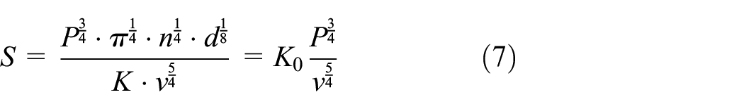
where

And the grinding area of a single grinding stone S in any grinding parameter combination can be determined using equation (9)
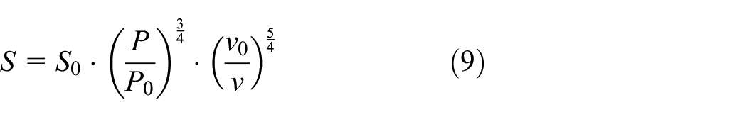
From the analysis of the equation (9), the grinding area S is only related with the reference grinding area S0, the grinding power P, and the travel speed of a grinding train v. Consequently, the quantitative relation between the grinding amount and grinding parameters for one single grinding stone is constructed when the grinding stone rotation speed n and the deflection θ are determined.
Calculation of the reference grinding area S0 based on an interval segmentation approach
Interval segmentation approach
The grinding ability of a grinding stone is related to the concrete grinding location on a rail profile, and it satisfies the following condition when the travel speed of a rail grinding train v and grinding power P are the same: inner gauge corner > outer gauge corner > rail top. 20 It can also be expressed that the grinding ability is related to the curvature of the arc section at the grinding location, the curvature is bigger, and the grinding ability is stronger. The grinding ability can be evaluated using grinding area; the reference grinding area S0 varies at different grinding locations, and it also satisfies the condition that is consistent with the grinding ability. Therefore, the S0 at different locations need to be calculated separately. Taking the standard 60 kg/m rail that is widely used in China railway as an example, it contains five arc sections with different radii and the values of S0 vary for different arc sections. But it could be treated as a constant in an arc section with the same radius even though the rail profile is a worn one, because the difference of the curvature for an arc section generally is not large. This method can avoid calculating the S0 values at every different location thereby reducing the computational cost. Let the gauge corner in the working side be positive, and the one in the non-working side be negative. Taking the GMC-96x rail grinding train as an object, the maximum deflection angle in the rail working side is +63.5, the corresponding maximum deflection angle in the non-working side is −20°, and the whole section can be divided into five grinding segments combined with the geometric characteristics of the 60 kg/m rail profile. The values of reference grinding areas S0 in every arc section are the same, and the specific segmentation result is illustrated in equation (10) and Figure 2


Rail grinding interval segmentation for 60 kg/m rail.
Calculation of the reference grinding area S0
A practical grinding experiment needs to be carried out to calculate the reference grinding area S0 in different segments. Furthermore, as the grinding angle difference of every segment covers from 3.8° (segment c) to 50.5° (segment a), it is obviously not appropriate to take the grinding area in a single specific location (single one angle) as the reference grinding area. Otherwise, the calculation error of S0 will be large when the rail profile is seriously worn. Therefore, multiple tests at different locations (exactly different deflection angles) in the same segment are carried out to obtain the grinding area, and the mean value of these grinding areas is regarded as the final reference grinding area S0. The specific flowchart of the approach is illustrated in Figure 3.

Flowchart of the calculation for reference grinding area S0.
Every 100 m, a test point is selected in a 500-m-long test rail line, and the initial profiles at the selected five test points A, B, C, D, E are obtained using measuring equipment. A grinding pattern, in which the reference grinding power is P0 and the travel speed of the grinding train is v0, is used to grind the profile of the test rail line using GMC-96x grinding train. Then the final rail profiles at those five test points are measured again, and the actual grinding areas of every segment at all test points
At last, the actual grinding areas of every grinding segment at all test points for a single grinding stone

where Ni is the number of grinding stones in the corresponding grinding area. The reference grinding area S0i of every grinding segment is obtained by averaging the calculated grinding areas at the five test points. The calculation formula is as shown in equation (12)

Grinding profile prediction based on accurate integral with cubic NURBS
In order to predict the grinding profile in any grinding pattern, the cut points formed by the end surface line and the rail profile in the corresponding grinding area are determined accurately based on the sequential forming mechanism after the grinding area of a single grinding stone is obtained. It is easy to obtain the corresponding cut points for a non-worn standard rail profile because it is formed by multiple arc segments. But it is hard to determine the cut points accurately for a worn rail profile because the rail profile is a kind of a typical free curve, and the grinding area is usually small. To determine the cut points accurately, a precision model of the rail profile needs to be constructed, and then the accurate area integration could be calculated.
A rail profile model is constructed based on the cubic NURBS curve method considering the characteristic that the rail profile is a kind of a free-form curve. The calculation formula is shown in equation (13)

where {P
i
} are the reference points, {ωi} are the weight factors, {Ni,3(u)} are the B-spline basis functions of degree p that are defined in the aperiodic and non-uniform knot vector

where

Then, the cut points are calculated when the corresponding grinding area Si is determined using the accurate area integral with cubic NURBS. The accurate calculation method of area integral quantity with cubic NURBS that was proposed by Deng et al. 22 is used to determine the precision cut points during the calculation process. The calculation principle is illustrated in Figure 4.

Determination method of the cut points based on accurate integral with cubic NURBS.
The cubic NURBS curve lp is transformed into a cubic rational Bézier curve using the formula as shown in equation (16)
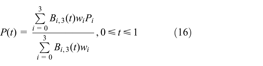
where {Bi,3(t)} is the Bernstein polynomial. The knot vector of the Bézier curve is

where the new knot

Then the new weight factor

where i = 0, 1, …, n if l = 0; i = 0, 1, …, n+l if l = 1, 2, …, s. And

The integral parameter Si is

where e =−ωi0+ 3ωi1− 3ωi2+ωi3; p, m, n, R1, R2, R3, Q1, Q2, Q3, Z1, Z2, Z3 are undetermined coefficients that could be calculated by equation (29) given in the literature by Deng et al. 22
Therefore, the area
Flowchart of the rail grinding profile prediction method
Figure 5 shows the flowchart of the proposed rail grinding profile prediction method, in which the rail profile of the standard 60 kg/m rail in China is still regarded as the object.
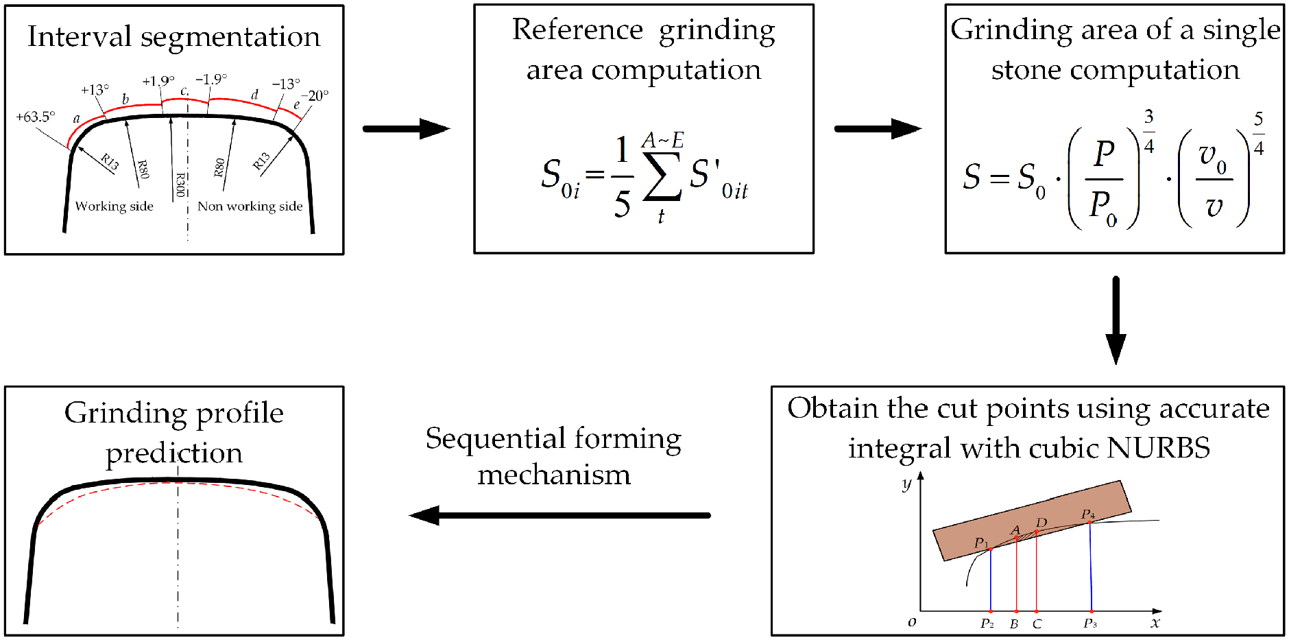
Flowchart of the proposed prediction method.
First, the rail profile is divided into five segments using the interval segmentation approach based on the rail profile geometric characteristics and the grinding angles range of a grinding rail train. Second, the reference grinding areas S0i of every segment are obtained using the method proposed in the section “Calculation of the reference grinding area S0” since the rail profiles before and after grinding operation are measured. Third, the actual grinding areas of every segment in a grinding pattern are calculated using the approach proposed in the section “Quantitative relations between grinding amount and grinding parameters for one single grinding stone.” Fourth, the cut points in the corresponding grinding area are determined using the accurate integral area with the cubic NURBS curve proposed in the section “Grinding profile prediction based on accurate integral with cubic NURBS.” Finally, a prediction rail grinding profile is obtained based on the sequential forming mechanism.
Experiment and discussion
Experiment scheme
The accuracy of the proposed method is validated in an actual railway line with the standard 60 kg/m rail profile in China. A 500-m-long in-service railway line is selected as the test line in the grinding operation site, where the GMC-96x is taken as the rail grinding train, five equidistant test points are marked in the test line, the grinding power P is 15.8 kW, and the travel speed of the rail grinding train is 12 km/h. A laser rail profile measurement device as shown in Figure 6 is used to measure the rail profile before and after grinding operation, which is shown in Figure 7.
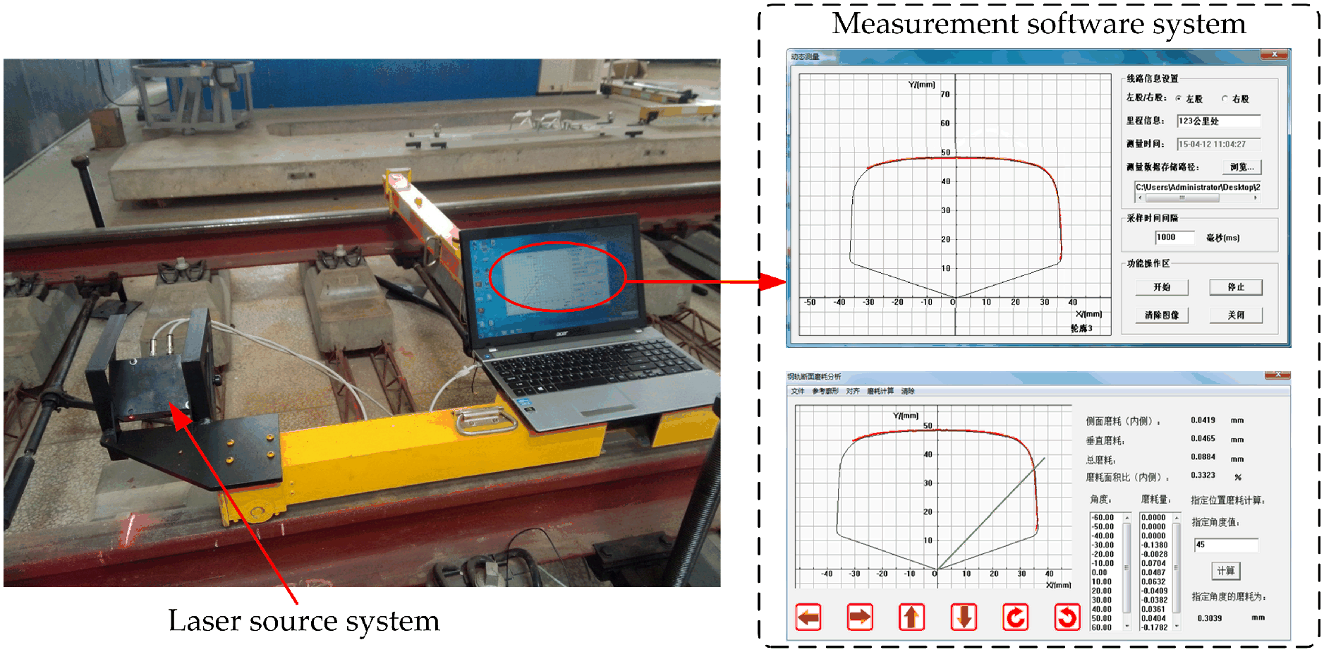
Rail profile measurement device and software.

Rail profile measurement: (a) before grinding and (b) after grinding.
The final prediction rail grinding profile is obtained using the prediction process proposed in the section “Flowchart of the rail grinding profile prediction method,” and the obtained rail grinding profile is compared with the actual measured result to test the accuracy of the proposed method. Besides, the N-KG proposed in the literature by Yang et al. 3 is also used to predict the rail grinding profile to compare with the prediction accuracy of the proposed method.
Accuracy test approach
To test the prediction accuracy of the proposed method, the normal length is regarded as the accuracy evaluate index. 23 In Figure 8, a point named T on the rail profile within the grinding range is selected based on certain rules 23 after alignment of the prediction profile with the actual measured profile, the center of the corresponding arc O is determined, and the normal OT and the actual profile intersect at R, then the length of line TR is the value of the accuracy evaluate index d. Its calculation formula is as shown in equation (22)

where dOT is the distance between point T and center O, dOR is the distance between point R and center O. The d value is positive when T is a point outside of the actual measured profile; and it is negative when T is a point inside of the actual measured profile. Therefore, the absolute value of the d value da is taken as the accuracy test index. The smaller the da value, the more accurate is the prediction method.
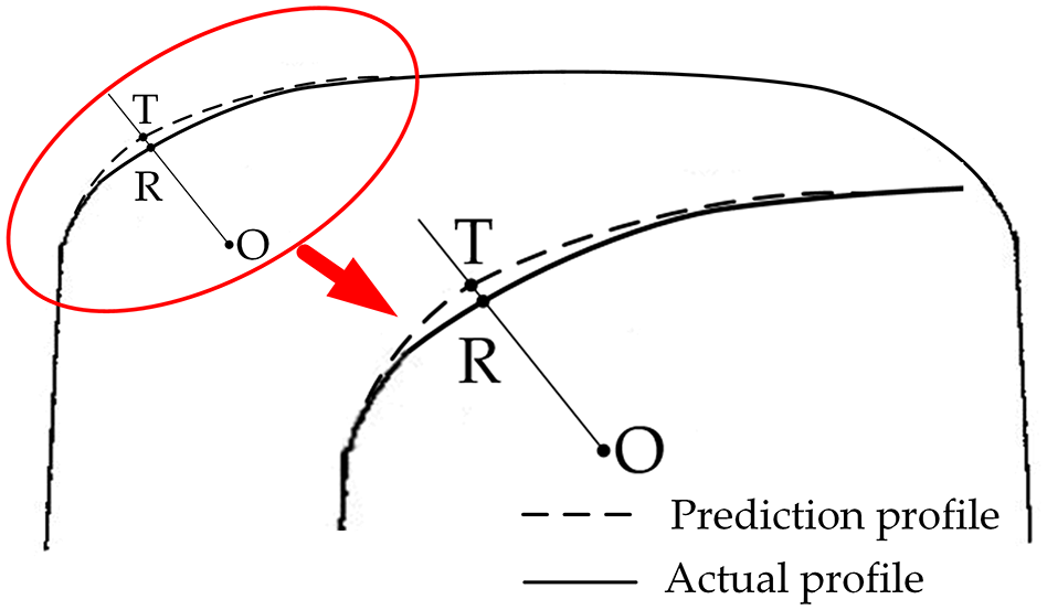
Normal length computation approach.
The width of the 60 kg/m rail profile is about 73 mm, and it will be time-consuming if the normal length values of every point are calculated. Therefore, obviously more attention should be devoted on the normal length of the points that affect the travel stability of a train. In practical, the points where the deflection angle is 45° and the points with the abscissa values −30, −25, −20, −15, −10, −5, 0, 5, 10, 15, 20, 25, and 30 mm are often regarded as the test points for the standard 60 kg/m rail. 23
Results and discussion
Rail grinding experiment is carried out according to the experiment scheme that is proposed in the section “Experiment scheme,” and a prediction result corresponding to a grinding pattern is obtained using different prediction methods including the proposed IS-AIN and N-KG. The final prediction results are shown in Figure 9.
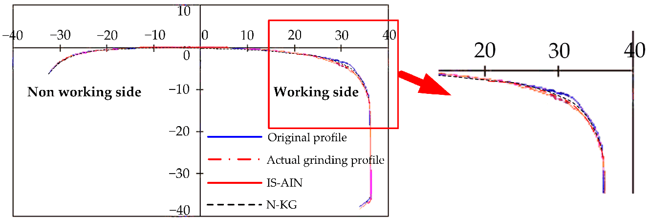
Prediction results using different methods.
Taking the actual rail grinding profile obtained by the measurement device after grinding operation as a standard, the normal length is regarded as the accuracy index, and the accuracy test results of different prediction methods are illustrated in Table 1. From the analysis of Table 1, the mean values of da obtained separately for IS-AIN and N-KG are 0.027 and 0.033 mm, respectively, which indicates that the proposed IS-AIN is more accurate than N-KG. It could be also observed that the variance of IS-AIN is 0.000293, which is higher than the corresponding value of N-KG, 0.000282. It shows that the prediction stability of the proposed method basically agrees with N-KG.
da values of different prediction methods.
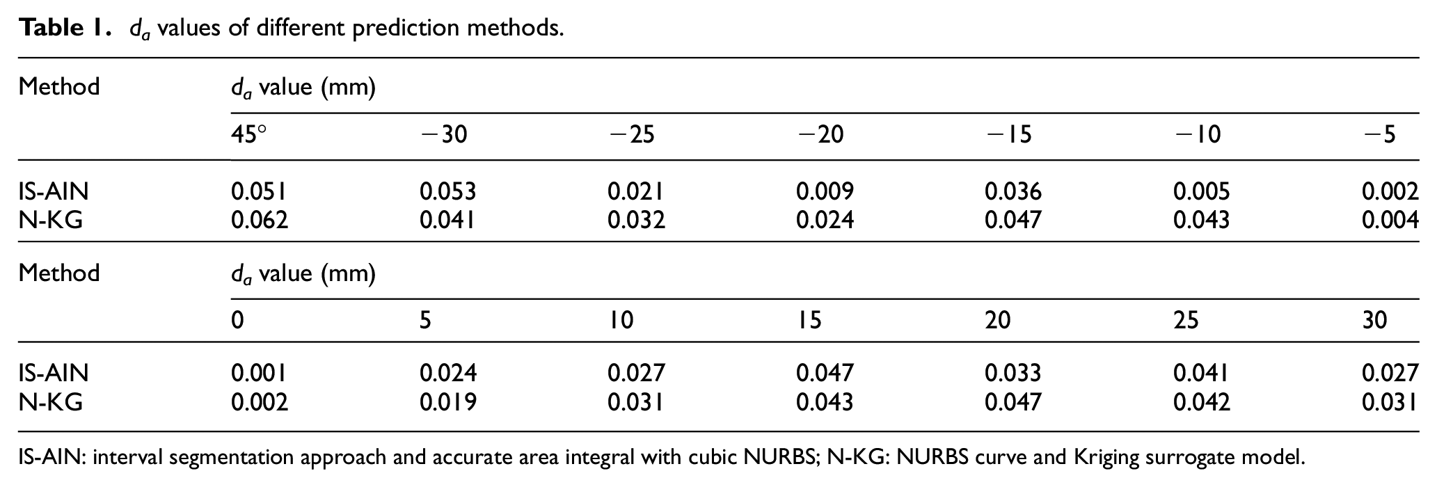
IS-AIN: interval segmentation approach and accurate area integral with cubic NURBS; N-KG: NURBS curve and Kriging surrogate model.
The proposed method and N-KG are implemented in the Matlab 2018b and examples are run on Windows 10 64bit with a 2.8 GHz CPU and 8.0 GB of RAM. The N-KG is investigated for a performance comparison with the proposed method. Table 2 shows the computational time, memory consumption, and CPU cost of the two methods. The results indicate that the proposed method has less computational time, memory consumption, and CPU cost for N-KG. In sum, the proposed method is not only highly accurate, but also highly efficient. Besides, the stability of the proposed method basically agrees with N-KG.
Comparison of the computational time, memory consumption, and CPU cost of different methods.

CPU: central processing unit; IS-AIN: interval segmentation approach and accurate area integral with cubic NURBS; N-KG: NURBS curve and Kriging surrogate model.
Conclusion
The IS-AIN method is proposed for the rail grinding profile prediction in any grinding pattern, especially for the design of a personalized target profile at the grinding operation site. An interval segmentation approach based on the geometric characteristic of a rail profile is proposed to improve the prediction accuracy and efficiency. The reference grinding area is used as the grinding amount index in a segment to improve the efficiency further. The accurate area integral with cubic NURBS is used as the grinding area calculation approach to improve the prediction accuracy. The accuracy and stability of the proposed method are analyzed by comparing the N-KG, and the rail grinding profile prediction effect is verified by a practical experiment in an in-service railway. The results of the performance assessment and comparison indicate that the proposed IS-AIN method is more accurate and efficient. This method could be applied to predict the rail grinding profile in any grinding pattern before practical process of rail grinding, which could provide a basis and a verification method for the design of rail grinding parameters. The design rationality of grinding pattern will be increased, and the rail grinding quality would be improved too.
Footnotes
Acknowledgements
The authors gratefully acknowledge the technical support from Mr Demin Liang of Beijing Time Technology Co., Ltd.
Handling Editor: Crinela Pislaru
Declaration of conflicting interests
The author(s) declared no potential conflicts of interest with respect to the research, authorship, and/or publication of this article.
Funding
The author(s) disclosed receipt of the following financial support for the research, authorship, and/or publication of this article: This research was funded by “the Scientific Research Program Funded by Shaanxi Provincial Education Department, grant number 19JK0903,”“the Natural Science Basic Research Plan in Shanxi Province of China, grant number 2019JQ-815, 2019GY-147,” and “the Doctoral Researchers Boosting Program of Xi’an Shiyou University.”