
Abstract
Based on the project of digging through the pile foundation of adjacent Qingdao Metro Line 11 at Zhangcun Station of line 4, orthogonal simulation research was carried out, and the influence of different underground running length of adjacent bridge pile was analyzed. Research findings were as follows: (1) The maximum vibration speed generated by the original solution bridge pile is 0.69 cm/s, which is too safe. After the optimization of the scheme, although the maximum vibration velocity generated by the bridge piles is 1.02 cm/s, an increase of 10 m in the blasting section can effectively speed up the construction schedule. (2) Combined with the field monitoring data, it was found that the monitoring data of the optimized scheme was consistent with the simulated data, which verified the accuracy of the simulation, and the new scheme reduced the construction budget by about 15%. (3) The vibration velocity attenuation degree of the rock layer is mainly composed of silty clay > coarse sand > micro weathered granite. (4) Through this optimization simulation, using Ansys/LS-DYNA to modify the K file to apply blasting parameters and initiation points, to obtain an efficient plan and improve the tunnel construction efficiency.
Introduction
The rapid development of modern cities has put forward new and higher requirements for transportation, and the means of transportation are developing toward the direction of spatialization. In the future, the complete elevated transportation and underground transportation will largely eliminate a series of problems in ground traffic. With the continuous development of transportation, urban overhead and underground traffic form grade separation, and their mutual influence is growing in the process of construction. 1 One of the increasingly prominent problems is engineering problem of the subway tunnel construction through viaduct or urban light rail pile foundation, especially the vibration response of bridge pile foundation during tunnel blasting construction.
At present, the research on the impact of blasting construction on adjacent buildings has received extensive attention from scholars at home and abroad. They mainly studied the ground settlement response caused by blasting excavation,2–7 the impact of vibration blasting on adjacent buildings,8–16 and the basic theory of blasting vibration.17–24 Among them, Li et al. 25 achieved reasonable prediction and effective control of blasting vibration through blasting test on surface vibration and theoretical research on vibration law. Duan Limin et al. 26 studied the effect of tunnel blasting excavation on the vibration velocity and frequency of the adjacent existing high-voltage tower through field test and numerical simulation, and discussed in detail the relationship between the transverse distance from the detonation center and the peak velocity. He et al. 27 used the FLAC3D and combined the engineering practice to analyze the surface subsidence caused by the blasting load of subway tunnel and summarized the settlement law. Li and Zhiwei 28 simulated the point source explosion in the tunnel with the help of LS-DYNA software, and revealed the response characteristics of the continuous beam bridge with plate rubber support under the blasting impact in the adjacent underground tunnel and its variation law with the rise and fall of water level. Guan et al. 29 explored the vibration response and damage of non-bearing members under blasting vibration by establishing a three-dimensional full-structure model for the damage caused by tunnel blasting vibration. Hou et al. 30 used ANSYS/LS-DYNA to simulate the rock mass blasting and the support structure of the mid-partition with the fluid-solid coupling method, and studied the dynamic response and failure mechanism of the mid-partition. Tian et al. 31 carried out a series of blasting vibration tests based on the Dizong tunnel to explore the propagation law of blasting vibration velocity in the stratum, and programmed the power spectrum, wavelet energy, wavelet packet energy analysis, and other signal processing with the help of MATLAB to analyze the propagation law of blasting vibration in the ultra-large section shallow tunnel. Jong-ho Shin et al. 32 studied the impact of blasting-induced vibration on adjacent tunnels through numerical simulation combined with field test results, and proposed a guide for blasting protection zone based on the study of blasting parameters. Jeon et al. 33 estimated the impact of explosive-induced vibration on the structural stability of adjacent tunnels based on the allowable peak particle velocity (PPV), and estimated the allowable blasting distance by using the finite difference method, and the behavior of concrete lining and bolt is tested and its stability is evaluated during blasting.
Existing results mainly focus on the impact analysis of tunnel blasting on surface structures and adjacent or lining tunnels in existing tunnels, while the impact analysis of bridge piles in close proximity is less. Most research results of domestic scholars34–38 studies on the impact of bridge piles without taking blasting vibration into account. Wu et al. 36 established a simplified three-dimensional finite element model of tunnel, pipe segment and pile foundation on the background of shield tunnel crossing viaduct pile foundation of Nanjing Metro line 3, and analyzed the influence of small clear spacing of tunnel crossing pile foundation on the stress and deformation of the ground and pile foundation. Liu et al. 39 analyzed the impact of shield excavation on 2×2 pile group foundation by using ANSYS and FLAC3D software, combined with the actual simulation of Ningbo subway project. Zhang et al. 40 combined theoretical analysis with numerical simulation and test data to study the theoretical response law of shield tunnel construction to adjacent bridge pile foundation and the analysis of risk control index. However, mine blasting, the common method of subway construction, has a greater impact on the adjacent bridge pile foundation.
Through the review of previous studies,41–48 it was found that the research of tunnel blasting construction mainly focuses on the vibration response analysis of the surface buildings. The analysis of the tunnel passing through the adjacent bridge pile is mostly based on the shield construction or mechanical excavation, and the analysis of the impact of the blasting vibration on the nearby bridge pile is lacking, resulting in the need of an in-depth analysis. Based on the theoretical research and the lack of practical engineering support, and after visiting a number of tunnel construction sites, it was found that the tunnel, subway, and other work areas of the blasting plan refer to the design code, and in view of special circumstances must rely on the experience of technical personnel, the lack of a simple method to guide the blasting construction in a specific environment.
For the problems summarized above, taking the underground excavation section of line 11 of Zhangcun Station of and line 4 of Qingdao City as the engineering background, this article uses finite element ANSYS/LS-DYNA to simulate, through the analysis of blasting vibration and the vibration response of the bridge pier, near research for different influence on the vibration of the bridge pier of blasting scheme, blasting construction project, to determine the most optimal solution, and summarize the auxiliary methods of blasting design with simulation software. And the technical route is as follows:

Establishment of calculation model
Materials and methods should be described with sufficient details to allow others to replicate and build on published results. Please note that publication of your manuscript implicates that you must make all materials, data, computer code, and protocols associated with the publication available to readers. Please disclose at the submission stage any restrictions on the availability of materials or information. New methods and protocols should be described in detail while well-established methods can be briefly described and appropriately cited.
Research manuscripts reporting large datasets that are deposited in a publicly available database should specify where the data have been deposited and provide the relevant accession numbers. If the accession numbers have not yet been obtained at the time of submission, please state that they will be provided during review. They must be provided prior to publication.
Interventionary studies involving animals or humans and other studies require ethical approval from the authority and the corresponding ethical approval code.
Geological situation of construction
Part of the main structure of Zhangcun Station, Qingdao Metro Line 4 Civil 09 Work Area, passes through Metro Line 11 and crosses the intersection of Songling Road and Lizhai Road. The starting point mileage of the station is YD (Z) K19 + 698.555, and the ending point mileage of the station is YD (Z) K20 + 215.055. The hidden digging section starting at YDK19 + 797.155 and ending at YDK19 + 863.605 is within 66.45 m at the intersection of Songling Road and Lizhai Road. The schematic plan is shown in Figure 1. The hidden digging section of the station foundation pit passes through the line 11 intervals, The A11 and A12 bridge piles of the intervals of the line 11 are located on both sides of the main structure of the station foundation pit. The minimum distance between the A11 bridge pile and the hidden digging section is 7.11 m, and the minimum distance between the A12 bridge pile and the hidden digging section is 4.81 m. In order to ensure the safety of the bridge pile structure, the vibration speed should be controlled at 1.5 cm/s. The covering soil of the right line of hidden digging section is 11 m thick, and the covering soil of the lift line is 14 m thick, as shown in Figure 2. The hidden digging section is mainly located in moderately weathered granite (massive cataclastic rock), and the vault is partially located in highly weathered cataclastic rock, while most of the rest are located in medium-coarse sand, mixed with silty clay and plain fill. Physical and mechanical parameters are determined based on tests and available data, as shown in Table 1.

Schematic plan of open and hidden excavation section of Zhangcun Station of Qingdao line 4.
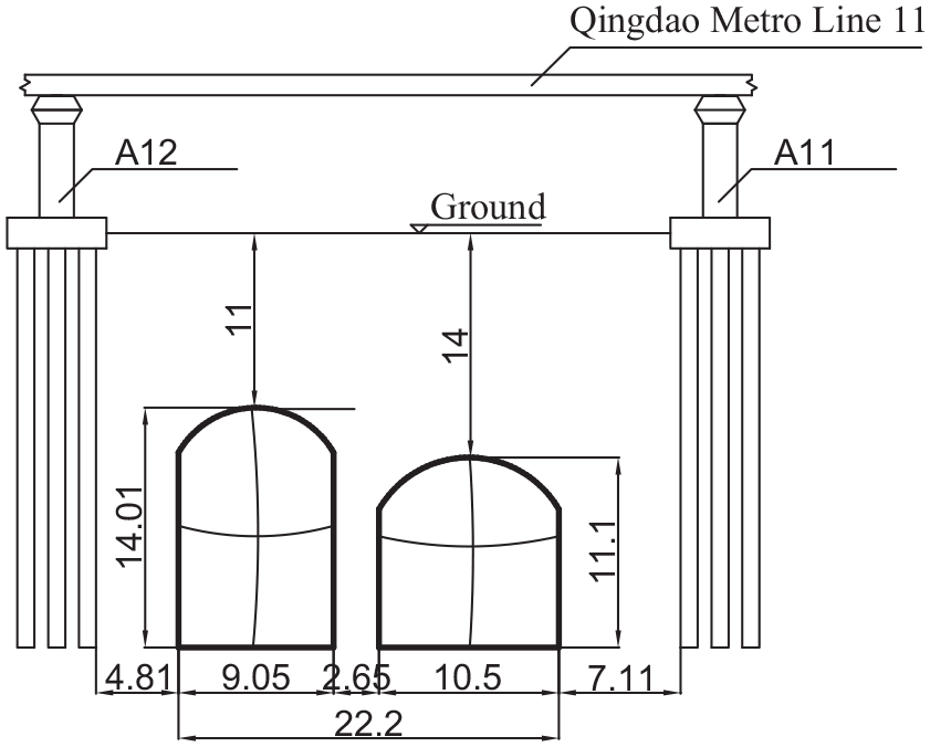
Profile of blasting area in Zhangcun Station of Qingdao Metro Line 4.
Physical and mechanical parameters of rock and soil mass.

Songling Road is an urban arterial road with large traffic flow. The urban pipe network under the road is crisscrossed, and all of them are trunk networks. The hidden digging section is conducted without pipeline relocation, and it is close to the bridge pile of line 11. The blasting vibration velocity must be strictly controlled, and monitoring and measurement should be strengthened. The maximum ground settlement should ensure the safety of the pipeline. The underground excavation section is constructed by blasting with mine method, and it is easy to collapse after excavation according to the geological prospecting results. Because the time limit is tight and the task is heavy, the rationality of the blasting scheme is particularly important.
Numerical model
As a commonly used display dynamic analysis software, ANSYS/LS-DYNA’s algorithm is particularly suitable for analyzing various complex dynamic problems, such as high nonlinear problems such as explosions, and has great advantages for solving fluid-solid coupling problems. Therefore this article uses ANSYS/LS-DYNA19.0 software for numerical simulation. First, use the DesignModeler module in ANSYS WORKBENCH19.0 to perform geometric modeling, and then use the powerful meshing capabilities of the ANSYS APDL to mesh and assign material properties, add boundary conditions, and finally add fluid-solid coupling conditions and parameters of No. 2 rock emulsion explosive by modifying the K file, and use LS-PrePost 4.3 for post-processing.
According to the actual geological conditions and the maximum range of the maximum adverse impact caused by the uncoupled explosive explosion, a numerical calculation model with length × width × height of 100 m×120 m×50 m was established by using ANSYS software, and the grid was divided. The calculation model after partitioning is shown in Figure 3. The numerical model of air is only built around the blast hole, and the length×width×height is 60 m×40 m×24 m. In order to ensure the finite volume model to simulate the air as an infinite body, non-reflection boundary is set around the model. The boundary conditions around the whole model (front, back, left, and right) are set as horizontal constraints, and the vertical constraints are set at the bottom of the model. The upper surface of the model is regarded as the ground and set as the free boundary.
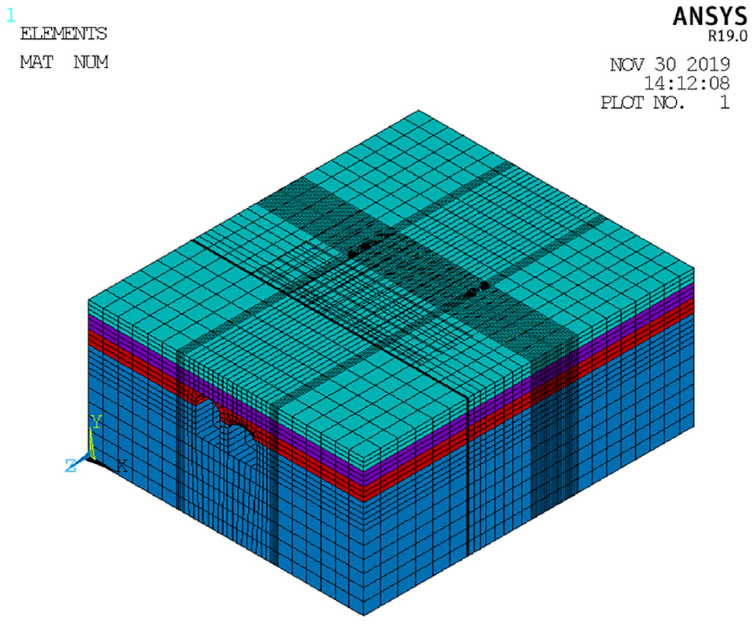
Calculation model.
Constitutive relations (and equations of state)
Constitutive relation and state equation of explosives
Explosives use *MAT_HIGH_ EXPLOSIVE_ BURN high explosive material, and JWL (jones-wilkins-lee) state equation of explosive is adopted as follows 49

where
Constitutive relation and state equation of air
The constitutive relationship of air adopts the *MAT_NULL model in LS-DYNA software, and the state equation of air 49 is

where
Constitutive relation of rock and soil
The model of granite was made of *MAT_PLASTIC_KINEMATIC. The model uses the following formula to measure the yield stress 49

where ε is the strain rate. C is strain rate parameter for Cowper Symonds strain rate model. P is strain rate parameter for Cowper Symonds strain model. The stress-strain curve is shown in Figure 4(a).

Stress-strain curve of constitutive relation: (a) when β = 0, the curve trend is kinematic hardening when it is broken line, when β = 1, the curve trend is isotropic hardening when it is solid line, (b) pressure is positive in compression. Volumetric strain is given by the natural log of the relative volume and is negative in compression. Relative volume is a ratio of the current volume to the initial volume at the start of the calculation. If the pressure drops below the cutoff value specified, it is reset to that value. When VCR = 1 is selected, crashing options off, loading and unloading follows the input curve. When VCR = 0 is selected, the volume crashing option is on, the bulk unloading module is used.
The material model of other soils is *MAT_ SOIL_AND_FOAM. The stress-strain curve is shown in Figure 4(b).
Constitutive relationship of bridge pile and tunnel initial lining
Reinforced concrete structure. The constitutive relation adopted is the *MAT_BRITTLE_DAMAGE constitutive model.
Simulation of tunnel excavation process
In the original design blasting scheme, the hidden digging section is broken from top to bottom according to the scope of the palm face, and the hole is excavated step by step according to the CRD. Within 44.45 m from the beginning of the excavation (let

Tunnel blasting section of original blasting scheme.
In order to improve the construction speed and increase the footage under the premise of ensuring safe construction, numerical simulation of different working conditions is adopted to optimize the scheme. There are many factors influencing blasting vibration and the situation is very complicated. This article only discusses the following two directions:
Increasing the blasting section, increasing the length of the tunnel for mining blasting construction. On the basis of the existing scheme, each additional 5 m (length of right line blasting area
Increasing or decreasing the blasting footage of one construction cycle. The blasting footage of the existing blasting scheme is 0.5 m, and different blasting footage (
Based on the above analysis, the orthogonal numerical simulation is set up, as shown in Table 2. With the help of computer software ANSYS19.0/ LS-DYNA, the orthogonal simulation method is used to optimize the blasting scheme. This method has great convenience and will be the trend of assisting in the design of blasting scheme in the future. According to the ratio between the length of blasting area and the depth of gun hole as required in Table 3, the partial excavation construction simulation of CRD method was conducted.
Orthogonal numerical simulation table of blasting scheme.

Orthogonal simulation scheme.

Analysis of calculation results
According to the established simulation scheme, the original blasting scheme can be obtained from Figure 4 as scheme 3. Compared with schemes 1, 2, and 3, according to the expert evaluation and design regulations, plan 3 is the feasible plan. Although the safety factor of plan 1 and plan 2 is larger, it is more conservative. In order to ensure the construction progress and reduce the construction period, these two plans will not be adopted.
Vibration response law of pile foundation along the axis of bridge pile foundation
Taking the model of scheme 3 as an example, numerical simulation analysis of the left and right lines of the tunnel is performed separately. And nodes along the axis of the bridge pile foundation are selected, and then the selected monitoring nodes are numbered as shown in Figure 6. The distribution of vibration velocity along the axis of the bridge pile foundation under the blasting load is analyzed. The vibration velocity distribution of each node of the pile foundation at each moment is shown in Figure 6.

Selection of nodes along the axis of the bridge pile foundation.
It can be seen from Figure 7 that when the left hole is blasted, the maximum vibration speed of the right bridge pile A11 is 0.85 cm/s at the 12th node, and the maximum vibration speed of the left bridge pile A12 is 1.01 cm/s at the 13th node. When the right hole is blasted, the maximum vibration speed of the right bridge pile A11 is 0.77 cm/s at the 12th node, and the maximum vibration speed of the left bridge pile A12 is 0.63 cm/s at the 13th node. The vibration velocity of the pile on the opposite side is less than that of the pile on the same side due to the gradual attenuation of blasting vibration energy in the rock and tunnel space in both the left hole and the right hole. It can be seen from the figure that the vibration velocity reaches the maximum at the lower part of the pile foundation (nodes 11, 12, 13, and 14), and gradually decreases along the axis of the bridge pile, and then small peaks appear at nodes 2 and 8 respectively. The reason should be that the attenuation degree of vibration wave velocity is different in different rocks. Node 2 is in medium-coarse sand, node 8 is in silty clay, and node 12 is in granite; therefore, it can be concluded that for the attenuation degree of vibration speed in different rock and soil, silty clay > medium sand > micro-weathered granite.

(a) Vibration response of each node of pile A11 under the left hole blasting. (b) Vibration response of each node of pile A12 under blasting in left hole. (c) Vibration response of each node of pile A11 under right hole blasting. (d) Vibration response of each node of pile A12 under right hole blasting.
Comparative analysis of vibration velocities in X, Y, and Z directions
It can be obtained from section “Vibration response law of pile foundation along the axis of bridge pile foundation” that there are three peak points at nodes 2, 8, and 12. In this section, the blasting of the right hole in scheme 3 is taken as the research object to analyze the vibration of X, Y, and Z vectors at nodes 2, 8, and 12, and compare their characteristics.
Vibration effect of right hole blasting on ipsilateral bridge pile A11
Figure 8 shows the influence of blasting vibration on the bridge pile on the same side. At vibration velocity of nodes 2 and 8, the Z > Y > X, while at nodes 12, Z > X > Y. The decay rate of vibration velocity is the fastest at node 12, followed by node 2 and node 8.

(a) Three-direction vibration velocity of node 2. (b) Twelve three-direction vibration velocity of node 8. (c) Thirteen three-direction vibration velocity of node 2.
Vibration effect of right hole blasting on the bridge pile A12 on the opposite side
It can be seen from Figure 9 that the vibration effect on the different side bridge pile is roughly the same as that in 4.2.1. Therefore, it can be concluded that the propagation of three-direction vibration velocity is different in different geotechnical materials: In the aeolized granite, Z > X > Y, In medium coarse sand and silty clay, Z > Y > X. Therefore, the vibration response of the bridge pile is correspondingly different.

(a) Fourteen three-direction vibration velocity of node 2. (b) Fifteen three-direction vibration velocity of node 8. (c) Sixteen three-direction vibration velocity of node 2.
Influence of increasing blasting section on vibration velocity of bridge pile foundation
From the discussion above, it can be concluded that no matter what kind of geotechnical materials, the impact of Z vibration velocity on the pile is the largest. Therefore, in this section, scheme 3, 7, 11, and 15 are selected as the research objects, and the influence of blasting of left and right tunnels on the same and different side bridge piles is also considered. It is known from the above that the peak value of the total pile vibration velocity is at node 12, so it is only necessary to analyze the Z vibration velocity at the bridge pile foundation node 12, as shown in Figure 10.

(a) Vibration of the same-side bridge pile under left hole blasting. (b) Vibration of opposite-side bridge pile under left hole blasting. (c) Vibration of the same-side bridge pile under right hole blasting. (d) Vibration of opposite-side bridge pile under right hole blasting.
In order to more clearly show the comparison of the vibration speed, the vibration of the same-side bridge pile under the left hole blasting is set to ZZ, the vibration of the left-side blast pile on the opposite-side bridge pile is set to ZY, and the vibration of the right-side blasting on the bridge pile on the same side set to YY, the vibration of the right-side blasting pile on the opposite side set to YZ, and the peak and peak times at 12 nodes are shown in Table 4.
Peak values and peak moments of the vibration speeds of the four schemes.

From Table 4, it can be seen that the vibration speed of bridge piles caused by tunnel blasting in different schemes is in the range of 100–400 ms. The maximum vibration velocity that is 2.17 cm/s occurs when the right bridge pile responds to the blasting of the right tunnel using scheme 15. Meanwhile, when blasting the left tunnel, the maximum vibration velocity generated by the left bridge pile is 1.68 cm/s, both of which obviously exceed the limited vibration velocity of 1.5 cm/s and fail to meet the requirements. The maximum vibration velocity generated by scheme 7 and scheme 11 is only 1.02 cm/s < 1.5 cm/s, which meets the requirements and is the feasible scheme. For the original scheme 3, the vibration velocity is relatively small, and the maximum value is only 0.69 cm/s, which is relatively conservative. Scheme 3, 7, 11, and 15 were compared, among which scheme 11 was the most reasonable plan.
Influence of gun hole depth on vibration velocity of bridge pile foundation
From the above discussion, it can be seen that scheme 15 does not meet the requirements. Then, the vibration response generated by scheme 16 in the orthogonal simulation scheme is larger than that of scheme 15, so it must not meet the requirements. In addition, according to the theoretical analysis, scheme 5 and 6 are more conservative than scheme 7, and scheme 9 and 10 are more conservative than scheme 11, which may not be adopted. Only the five schemes of 4, 8, 12, 13, and 14 need to be discussed. According to the above, the z-direction vibration velocity of node 12 is still taken as the research object, and it can be seen from Table 4 that the maximum vibration velocity appears on the adjacent bridge pile. Therefore, simplified analysis can be made in this section. According to the simulation of schemes 4, 8, 12, 13, and 14, the z-direction vibration velocity of node 12 is obtained as shown in Figure 11. The peak times and peaks of the five schemes are shown in Table 5.

(a) Vibration of the same-side bridge pile under left hole blasting. (b) Bridge pile under left hole blasting. (c) Vibration of the same-side bridge pile under right hole blasting. (d) Vibration of opposite-side bridge pile under right hole blasting.
Peak values and peak moments of vibration speeds of the five schemes.

It can be seen from Figure 11 that the peak time range of vibration velocity is within 120∼360 ms. By comparing schemes 4, 8, and 12 with schemes 3, 7, and 11, the overall vibration velocity increased by 10%∼40% when the gun hole depth was 0.7 m compared with 0.6 m. It can be seen from Table 5 that when scheme 12 is adopted, the maximum vibration velocity generated by the right bridge pile during the right hole blasting is 1.66 cm/s < 1.5 cm/s, so this scheme is not feasible. Compared with scheme 13 and scheme 14, the overall vibration velocity increased by 20%∼40% when the gun hole depth was 0.5 m as compared with 0.4 m. And when scheme 13 is adopted, the maximum vibration velocity generated by the right bridge pile during the right hole blasting is 1.41 cm/s, close to 1.5 cm/s, while when scheme 14 is adopted, the maximum vibration velocity is 1.85 cm/s > 1.5 cm/s, which is not feasible.
For these five schemes, scheme 12 and scheme 14 obviously do not meet the requirements, while for scheme 13, although the maximum vibration speed generated is less than 1.5 cm/s, if a certain safety factor is adopted, scheme 13 is dangerous, so it is not recommended to use. For scheme 4 and scheme 8, under the condition that the vibration velocity meets the requirements, scheme 8 can better improve the construction efficiency, so it is recommended to adopt. By comparing scheme 8 and scheme 11, it can be found that the maximum vibration velocity produced by the two schemes is not much different, but the blasting section of scheme 11 is longer, and the amount of explosives used in each blasting is small, so the construction is safer, and the construction period is reduced, so it is suggested to use scheme 11. It can be concluded from the above discussion that the blasting section can be increased by 10 m without changing the original size of the gun hole, and the smooth construction can be guaranteed.
Comparison between monitoring data andsimulated data
When the new scheme is adopted, the change of vibration velocity is monitored for each advance blasting. Because it is inconvenient to arrange monitoring points on the pile body, monitoring points can only be arranged on the bridge pier, as shown in Figure 12. Settlement detection points were set up on the viaduct surface of Qingdao line 11, and monitoring points for settlement, tilt, and blasting vibration were set up at the bridge pier. In the extracted monitoring data, the blasting peak vibration velocity of every 1 m in the blasting section of 10 m was increased after the optimized scheme was adopted, as shown in Figure 13.

Monitoring point arrangement.

Peak vibration velocity every 1 m in newly added blasting section.
As can be seen from Figure 13, from the monitoring data, after the implementation of the new blasting scheme, the maximum vibration velocity generated by the bridge pier is 0.97 cm/s < 1.5 cm/s, while compared with the simulated data, the measured value is about 10% less than the simulated value. The main reasons are as follows: the simulated value of peak vibration velocity is close to the detonation point on the bridge pile, while the monitoring data is measured on the bridge pier, and the data at the monitoring point becomes smaller due to the shock absorption of blasting vibration through the air. All in all, from the monitoring data, the new blasting scheme is adopted for the tunnel blasting construction, and the adjacent pile foundation of Metro Line 11 is safe.
After the actual test of the project, the new scheme adopted can not only guarantee the demand of safety but also has great advantages in construction organization, personnel deployment, and budget estimation, reducing the construction budget by about 15%.
Conclusion
In this article, ANSYS19.0/LS-DYNA finite element software is used to conduct blasting simulation for hidden digging section of metro station passing through adjacent bridge piles. Through the numerical simulation of different blasting conditions and the comparison and optimization, it can provide efficient and safe blasting scheme for tunnel blasting construction. The feasibility of the scheme is proved by the construction, and the accuracy of the simulation is also verified. This article also has some limitations. Although the accuracy of the hole simplification has been verified, it still has some deviations. The conclusion of this article focuses on the practical application and lacks the summary of the general law of theory. However, the following conclusions obtained from this simulation are still of great significance:
By analyzing the blasting response law of the axial direction of the bridge pile, it was found that the peak value of vibration velocity on the bridge pile foundation occurs at the position of the bridge pile perpendicular to the detonation point. In addition, there are peaks of vibration velocity on different rock and soil layers. According to the characteristics of “upper soft and lower hard” of Qingdao strata, the attenuation degree of silty clay > medium-coarse sandy > aeolized granite was obtained through simulation.
Through the numerical simulation of the blasting scheme in the underground excavation section of Zhangcun Station of Qingdao Metro Line 4, the comparison and optimization of the original blasting scheme were conducted, and it was found that if the original blasting scheme was adopted, the maximum vibration velocity generated by the bridge pile was 0.69 cm/s. In order to control the vibration velocity of the bridge pile within a safe range and improve the construction speed as much as possible, the new scheme proposed will increase the blasting section by 10 m. It is found that with the new scheme, the maximum vibration velocity generated by the bridge pile is 1.02 cm/s, which has been verified by engineering practice to prove its accuracy, and greatly improved the construction efficiency, which has a strong significance of construction guidance.
Through the optimization simulation of the blasting scheme, this article proposes a method to assist in the design of the blasting scheme. First, the DesignModeler module was used for geometric modeling, and then ANSYS APDL was used for mesh division. Finally, based on the site measurement data, the parameters of the soil layer and the initiation point and initiation time were modified by modifying the K file. Then, orthogonal simulation is used to simulate and compare various blasting schemes and different working conditions to obtain the optimal blasting scheme, which reduces the problem of waste of manpower, material resources, and financial resources.
Footnotes
Handling Editor: James Baldwin
Declaration of conflicting interests
The author(s) declared no potential conflicts of interest with respect to the research, authorship, and/or publication of this article.
Funding
The author(s) received no financial support for the research, authorship, and/or publication of this article.