
Abstract
In this study, the seismic response of the anchorage used for switchboard cabinets at a power plant was presented based on the results of an experiment and numerical simulations. In the experimental study, shaking table tests were performed to investigate the overall structural behavior of switchboard cabinets. The finite element modeling was conducted using the ABAQUS program, and in order to validate the proposed finite element model, the natural frequency, stress, and displacement were compared with the experimental results. A slight difference was found in the results due to the problem cup-like deformation at the anchorage of the bottom, but it showed reasonable agreement when considering the results for all behaviors. Using the proven model, nonlinear dynamic analysis was performed using three types of a period waves. The maximum stress on the anchorage occurred when a long-period wave was applied, and the horizontal maximum displacement of the cabinet was approximately 10 times greater than when an ultra-short-period wave was applied. It is expected that the flexibility of the cabinet stiffness resulted in more structural weakness, especially under a long-period wave, and that is recommended to focus on displacement rather than stress when establishing seismic design guidelines for switchboard cabinets.
Introduction
The frequency of earthquakes has been increasing in recent years, and the damage associated with earthquakes is increasing as well. In particular, there have been many cases of damage to facilities due to earthquakes. In such cases, not only was the damage to the entire facility a problem, but the damage to non-structural elements installed in the affected facility was also found to significantly disrupt the performance of the entire facility. 1 Reviewing recent reports of earthquake damage shows that there have been increased cases of damage and destruction to non-structural elements, not structural elements such as Figure 1(a). 2 As shown in Figure 1(b) cite on Federal Emergency Management Agency’s (FEMA) report, the damage costs for non-structural components in the earthquake indicate that the recovery amount of earthquake damage for non-structural components is a significant proportion of the total earthquake damage recovery amount.3,4 While structural components secure sufficient stability for an earthquake, damage and destruction of non-structural components can lead to enormous economic losses as well as loss of life, resulting in a wide range of damage. Hence, seismic design of non-structural elements is very important for buildings maintain their original functionality even if the damage to the main structural materials after the earthquake is minor. 5 In particular, a power generation facility with a special purpose can cause severe second and third damage and loss of lives if an unstable component malfunctions due to an earthquake. 6 Thus, earthquake-related researchers have been recently conducted studies on seismic design and reinforcement of various non-structural elements.
Figure 1.(a) Earthquake damage cases of non-structural components and (b) recovery cost ratio of earthquake damage.

Numerical model verification
In this study, the test and analytical results were compared with each other in order to verify the reliability of the numerical model. 7 The earthquake loads were generated using the shaking table.8,9 And its mechanism can be confirmed by the model using test data, and then the behavior characteristics of an anchorage connecting electric cabinet subjected to earthquake loading are investigated through numerical analysis.10–12 Ultimately, the reliability of the numerical analysis simulating the switchboard cabinet based on ABAQUS element was verified through comparison with the test results. 13
Experimental simulation method
Description of geometry
The experimental equipment used in the shaking table test was a single-door cabinet, and one single-door cabinet was installed on the shaking table in order to assess the behavior of the cabinet in the event of an earthquake, as shown in Figure 2.

Processing of the tested specimens.
In order to minimize the uplifting and rocking motion caused by vibration, the floor plate and steel jig were welded together, and the floor plate and jig were connected through eight anchors, similar to the actual anchor installation. Table 1 and Figure 3 show the specification of a single-door cabinet used in the experiment.
Test specimen description.


Dimensions of the cabinet.
Data measurement unit
The acceleration response was measured to calculate the transmission function by installing accelerometers in crucial locations, such as the center, top, and sides of the internal plate according to cabinet height. In total, eight load cells were installed together at the connection between the jig and the cabinet floor plate to measure pullout force of the cabinet anchorage. In addition, two linear variable differential transformers (LVDTs) were installed on the side of the short-circuit cabinet to measure relative displacement with the displacement response at the top and bottom of the cabinet, as shown in Figure 4.

Each sensor type and location.
Reinforcement for the specimen
The resonance searching test results showed that the impact signals such as banging and rattling in the cabinet as well as the local mode of internal boards made it difficult to measure the resonant frequency (refer to Figure 5(a)). Furthermore, the time history test using each seismic wave resulted in banging and rattling for the same reason. 14 IEEE Std. 344 specifies that banging and rattling should be considered in performance verification. 15 Therefore, in this experiment, the internal plates and components in the cabinet were welded and reinforced as shown in Figure 5(b) in order to minimize banging and rattling, and Figure 5(c) shows the resonance search test results graph.16,17

Cabinet reinforcement for test: (a) resonance search test before reinforcement, (b) reinforcement of components, and (c) resonance search test after reinforcement.
Overall experiment sequence
A resonance search experiment was performed with a sine sweep test to measure the possible structural deformations before and after the experiment. It was performed once in each axis direction, (X), (Y), and (Z), and the magnitude of the acceleration signal was set at 0.07 g in order to minimize the damage to the cabinet. The search range was 1–50 Hz, and the frequency increase rate was 2 octave/min. The procedure used for the shaking table experiment is shown below in Table 2.
Procedure of the shaking table experiment.

UHS: uniform hazard spectrum.
Input seismic waves
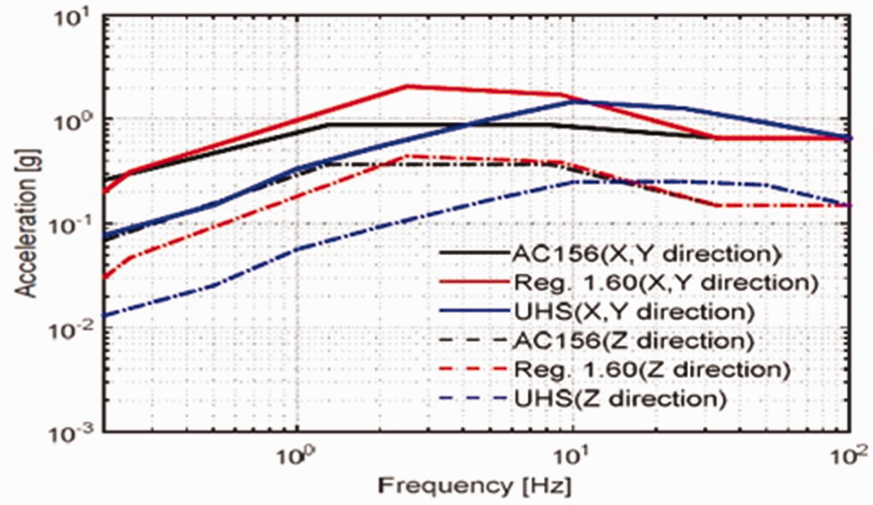
To evaluate the seismic performance of the switchboard cabinet, three seismic input waves were used. The first one was a Reg. 1.60 design spectrum based on the power plant design basis, and the second one was a Korean Nuclear Power Plant site–specific uniform hazard spectrum (UHS) motions in Uljin based on the regional characteristics.18,19 The last one was used in accordance with ICC-ES AC156, a method recommended by American Society of Civil Engineers (ASCE) to test the vibrations of non-structural elements such as switchboard cabinets. 20
Figure 6 presents Reg. 1.60 and UHS normalized to 0.67 g in the horizontal direction and 0.14 g in the vertical direction with respect to the zero period acceleration (ZPA) size of the AC-156 RRS according to the equivalent static structural load of the domestic building structure standard. For each seismic wave, the damping ratio was set to 5% in three axes using the horizontal (X, Y) and vertical (Z) RRS. 21
Required response spectrum (5% damping).
The single-cycle design spectrum acceleration (SDS) was derived as shown in equation (1), in accordance with the domestic architectural structural standards.
22
The seismic zone coefficient (S) was assumed to be seismic zone I to apply 0.22 g, and the single-cycle ground evaporation coefficient (Fa) was assumed to be solid soil ground (SD) to apply 1.5

The horizontal AFLX-H, ARIG-H calculated using
equation (2)
and
equation (3)
as given in ICC-ES AC 156, and the maximum value of AFLX-H shall not exceed 1.6 SDS. The z/h means the ratio of the location of the structure and non-structural elements. It is assumed to be 1 since it can be constructed on a loaded floor. The AFLX-V and ARIG-V are 67% of SDS and 27% of SDS, respectively. The main parameters of the RRS are shown in Figure 7 and Table 3


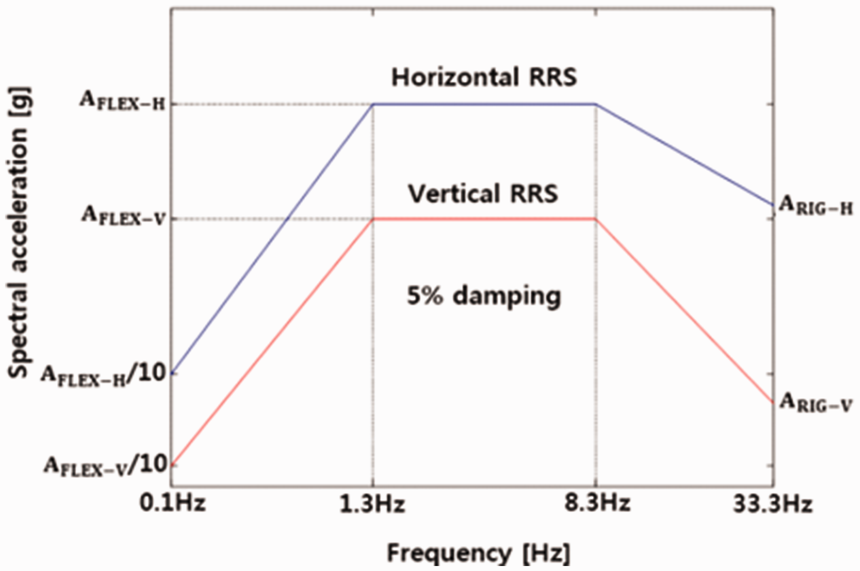
Required response spectrum of AC-156.
Shake table test parameter.

Numerical analysis simulation method
Finite element modeling of geometry
The finite element (FE) model was composed of three groups, which are the cabinet body, floor jig and anchor bolts, as shown in Figure 8(a). The interface between the cabinet body and floor jig was designed to have the sliding effect using contact surfaces. In total, 55,000 nodes and 99,800 elements were applied in the FE model. The dimensions used for modeling are the same as those specified in Table 1 and Figure 3.
Figure 8.Overall 3D-modeling geometry using ABAQUS program: (a) component of the 3D-model parts and (b) shape and FE mesh for the 3D-model.

Material properties
Table 4 below shows the material properties applied in the numerical analysis. The damping value is obtained proceeding Eigenvalue analysis using ABAQUS program, and then the values required for the numerical analysis were calculated using MATLAB program.
The material properties applied in the numerical analysis.

Damping (3%): this means that Alpha and Beta are Rayleigh damping coefficients.
Rayleigh damping
Consider a dynamic system as follows

In the case of Rayleigh damping, [C] is determined as follows

The damping of mode i is quantified by the damping ratio, ξi, the ratio of the mode’s damping to the critical value. If 
Thus,
Contact mechanism for components
The mechanical interaction between the top of the zig and cabinet bottom surfaces is modeled using a friction formulation in a tangential direction and hard contact in the normal direction so as to avoid penetration into each other. The penalty method is used for tangential behavior along with the coefficient of friction of 0.3. For normal interaction, the hard contact option is used, and separation was allowed after contact in the interaction model. The interaction between the top of the zig and the cabinet bottom surface is modeled as the slaves, and the top flange surface of the zig is modeled as the master.
Finite sliding as well as the penalty contact method is used for the interaction between the zig and cabinet. The welded regions such as the inner plate and cabinet body were modeled using tie constraints under the assumption of no separation at the weld locations. In addition, the contact mechanism was applied to the anchor used to connect between the cabinet and the jig using surface-to-surface function (Figure 9).

Assigned contact surfaces.
A tie constraint ties two separate surfaces together so that there is no relative motion between them, like the welded effect.
Surface-to-surface contact interactions describe contact between two deformable surfaces or between a deformable surface and a rigid surface, like the sliding effect. This function takes into account the dynamic behavior of the contact surfaces.
Load conditions
The seismic load applied to the analytical model acts on the point, generating an inertial force at the free end of the cabinet and resulting in dynamic behavior. This dynamic behavior produces a variety of responses depending on the shape of the cabinet and the relationship of the direction of load application. The seismic load applied to the numerical analysis was used in accordance with ICC-ES AC-156, a method recommended by ASCE to test the vibrations of non-structural elements such as switchboard cabinets. As Figure 10(a) shows, it is necessary to convert the seismic acceleration data before applying the seismic load. The direction (axis-Z) of the load used for the numerical analysis was determined based on the axis on which the LVDT was installed in the experiment.
Figure 10.(a) Conversion of earthquake input data to loading and (b) boundary conditions for numerical analysis.

The overall analysis proceeded by classifying it as an analysis to search for the natural frequency, and an analysis of earthquakes to observe the dynamic behavior of the cabinet and the stresses generated by the anchors. Eigenvalue analysis to obtain the natural frequency value was performed in order to fix the conditions regarding all boundaries. For dynamic analysis, only the axis-Z applying load direction was released, and the axes of X and Y were fixed (refer to Figure 10(b)).
Results comparison and model verification
Natural frequency
The resonance frequency of the cabinet was checked and the resonance search experiment was performed in order to assess the structural changes and the dynamic characteristics during the experiment. It was performed at a level of 0.07 g from 1 to 50 Hz, and based on results measured from the A12 acceleration sensor installed in the top of the cabinet, the resonant frequency was obtained as shown in Table 5 for each axis. The value of the axis-X for comparison with the natural frequency of the numerical model is 15.3 Hz.
Resonance search experiment results (Test Response).
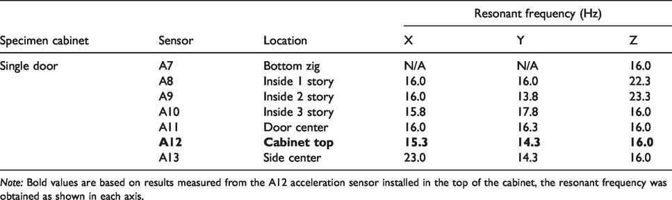
Note: Bold values are based on results measured from the A12 acceleration sensor installed in the top of the cabinet, the resonant frequency was obtained as shown in each axis.
In order to know the dynamic characteristics and natural frequency of a structure before performing time history analysis in this study, analysis up to the 10th mode was performed using the Lanczos method, which is a mode extraction method in ABAQUS. The criteria used to determine the main mode through eigenvalue analysis are generally determined according to the mass participation rate that contributes to the structure. As shown in Table 6, the mass participation rate in the Z direction is approximately 94% in the 5th mode, so the main mode of the Z-directional vibration mode can be determined. The natural frequency of the cabinet in the numerical model was found to be 16.6 Hz (the X-axis in the experiment and the axis-Z of the numerical model are the same axis). The experimental and analytical results were found to be approximately 92% matched.
Eigenvalue search analysis results.

The total effective mass at the axis-Z is 0.14995.Note: The mass participation rate in the Z direction is approximately 94% (0.14054/0.14995) in the 5th mode, so the main mode of the Z-directional vibration mode can be determined.
Relative displacement
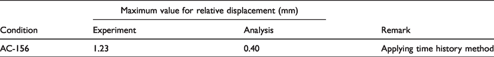
Below, Figure 11(a) shows the data obtained using the displacement response of the LVDT installed at the top (D1) and bottom (D2) position of the cabinet as a transfer function, and the relative displacement of the cabinet under the seismic wave is shown as well. Figure 11(b) shows the relative displacement obtained using numerical analysis for the same conditions, and Table 7 shows a comparison of the experimental and analytical results.
Figure 11. Relative displacement results: (a) comparison of relative displacement before and after reinforcement in the experiment and (b) analysis results of maximum displacement.

Comparison of displacement between experiment and numerical analysis results.
Anchorage response load
Figure 12 below shows the results of the anchorage pullout force of the time history test for each seismic wave in a single-door cabinet following reinforcement. It was difficult to measure the exact anchorage pullout force due to the local deformation of the floor plate adjacent to the anchor bolt. This is because of the rocking problem which causes cup-like deformation at the bottom of the cabinet. For this reason, the cabinet bottom was reinforced by welding using the plate, and the force applied to the anchor was measured (refer to Figure 5(b)).

Maximum anchorage load results.
Figure 13 below presents the anchorage stress results in the numerical analysis. In order to gain the pullout force of anchorage, the stress on the anchor was calculated by considering the cross-sectional area of the anchorage.

Each anchor stress under seismic loading.
Figure 14 below shows a comparison between the test and analysis results. There are slightly different results, except for LC2-1. The experimental data of LC2-1 are substantially different from the other experimental data. The bottom of the cabinet is subjected to an impact due to the uplifting, which leads to cup-like deformation around the anchor bolt.

Comparison between experiment and analysis.
Closer
In order to validate the proposed FE model, the natural frequency, displacement, and anchorage load were used in the comparison of numerical analysis results, and a reasonable agreement was found when comparing all of the behavior of the switchboard cabinets. From the analysis, a slight difference was found due to the rocking problem which leads to cup-like deformation as shown in Figure 15 at the bottom of the cabinet.
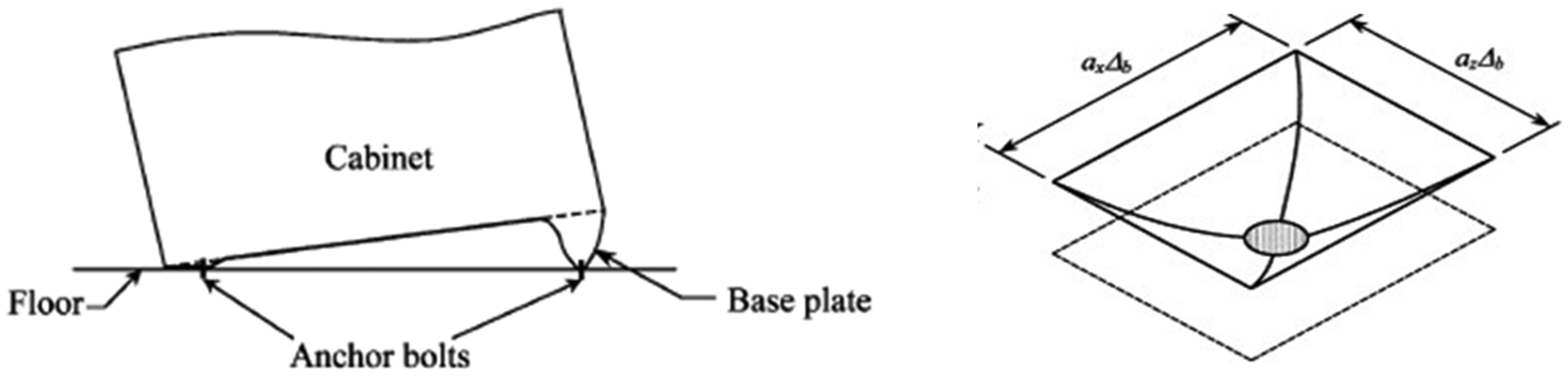
“Cup-like” deformation of base plate around an anchor bolt.
Analysis of vulnerability
Vulnerable characteristics under the seismic waves
For earthquakes, each region has different characteristics. Even in the same region, the specific damage can vary according to the period of the waves. 24 For instance, long-period waves occur in the El Centro region while short-period waves appear in the Mexico region. Since the frequency of earthquakes in Korea has recently been increasing, the vulnerability was analyzed by applying the occurrence of earthquake load on Gyeongju in Korea. 25
In this analytical study, using the validated numerical model, the effects of the three typical types of waves (a long-period, a short-period, and an ultra-short-period) on cabinet behavior were analyzed. Table 8 below shows the amplitudes of the waves applied to analyze the vulnerability of the cabinet to each kind of waves.
Three typical types of waves applied in the analysis.

Results and comparison
In order to investigate the effects of different periods of earthquake on the cabinet, the stresses on the anchors supporting the cabinets and the displacement of the overall behavior of the cabinet were analyzed through a numerical model. Tables 9 and 10 below compare the results of each condition.
Comparison results regarding each stress.

Comparison results regarding each displacement.

The stress of the anchor in the long-period wave is the greatest, and the results of the other waves are similar to each other. The difference in Von Mises stress of the anchor bolts embedded in concrete foundation appears to show that the application has a slight effect for the period of wave.
The horizontal maximum displacement of the long-period wave was approximately 10 times greater when the ultra-short-period wave was applied. It can be seen that the flexibility of the cabinet stiffness resulted in more structural weakness, especially under the long-period wave.
Conclusion
In this study, the seismic response of the anchor bolt used for freestanding equipment at a hydroelectric power plant, such as switchboard cabinets, was presented based on the results of experiment and numerical simulations. Validation of finite element analysis was performed based on the results of the shaking table test. Using the validated numerical model, the effects of the three typical types of waves (a long-period, a short-period, and an ultra-short-period) on cabinet behavior were analyzed. The results of the study are summarized as follows:
In order to improve seismic performance in the actual installation and application of cabinets, it is considered necessary to prevent inter-collision of the rocking mode and internal components by taking into account the internal frame of the cabinet.
An important point of the shaking table test of the switchboard cabinet is that if the lower plate is thin, the damage of the internal device according to the thickness of the lower plate may be greatly affected by the actual rocking of the switchboard. Thus, the damage level of the internal device depending on the thickness of the lower plate will be carried out as a future study.
In addition, the vulnerability was evaluated by applying seismic loads with three different types of period. Although the impact of earthquakes on anchors is judged to be insignificant, it is shown to have a significant impact on the overall behavior when examining the displacement.
In this connection, it is recommended to focus on displacement rather than stress when establishing seismic design guidelines for the switchboard cabinets in the future.
Footnotes
Handling Editor: James Baldwin
Declaration of conflicting interests
The author(s) declared no potential conflicts of interest with respect to the research, authorship, and/or publication of this article.
Funding
The author(s) disclosed receipt of the following financial support for the research, authorship, and/or publication of this article: This research was supported by a grant (19IFIP-B128598-03) from Industrial Facilities & Infrastructure Research Program (IFIP) funded by Ministry of Land, Infrastructure and Transport of Korean government.