
Abstract
Maintaining surface accuracy is crucial to realizing the required performance of membrane structure. However, compressive stress inevitably leads to wrinkling, and the accurate analysis of the stresses becomes significant. The present study analyzed membrane structures with discrete loads. First, a simple method was proposed and the stress field was accurately described using an Airy stress model. The first and second principal stresses were obtained, and regions of wrinkling with negative stress were predicted. Second, for a square membrane structure, vertical tensions around the boundary were applied such that in-plane stresses were more evenly distributed. Finally, to reduce the wrinkling areas more effectively, an arc-edge structure was designed by removing some areas of low-stress. Simulation results showed that the in-plane stress field distribution was described accurately and the wrinkling regions were diminished effectively with the proposed method.
Introduction
Membranes are used in a wide variety of engineering applications spanning from aerospace applications to civil structures owing to their tunable stiffness and light weight. 1 However, a membrane is usually assumed to have zero flexural stiffness, and there is out-of-plane deformation if any of the in-plane stresses are compressive. Maintaining surface accuracy is crucial to meeting the required membrane structure performance,2,3 and accurate analysis of stresses is therefore important.
Different methods of analyzing the stress fields of membrane structures have been proposed; Wong and Pellegrino4,5 studied the in-plane stress field in a square membrane with discrete forces applied on the membrane vertices and found that the stress field comprises identical corner regions under purely radial stress and a central region under uniform biaxial stress, with wrinkles appearing within the uniaxial stress regions. Zhang and colleagues6,7 proposed a membrane model with viable Young’s modulus and Poisson’s ratio, and then adopted parametric finite element discretization and a smoothing Newton method to obtain a numerical solution. The finite element method8,9 has been widely adopted; however, its use readily leads to divergent results. Coman and Bassom 10 built a numerical model to establish the nature of localized wrinkling according to Föppl-von Kármán nonlinear plate theory; however, the bifurcation theorem was introduced to track the bifurcation path, which is computationally expensive.
Luo et al. 11 proposed a topology optimization methodology to seek the optimal wrinkle-free design of macro-scale thin membrane structures; several holes were distributed on the optimal structures, and wrinkling disappeared as the areas of the structure reduced. Edge-trimming has been confirmed as an effective method of diminishing wrinkling without destroying the central region of the membrane structure. Luo and colleagues12,13 proposed a multi-material topology optimization approach for cable-suspended membrane structures and found that topology optimization is an effective method for the layout design of products; however, this method should be applied with the finite element analysis (FEA) method, which is usually computationally expensive. Bonin and Seffen 14 predicted the trimming level by converting the tensile model into a bending analogy model. This method is not intuitive and deformation gradients and any intrinsic length changes between a straight-edge model and an arc-edge model were neglected, which may lead to inaccurate results.
In our previous study, 15 we analyzed regular polygonal membrane structures subjected to equal radial forces and proposed a new stress-field distribution model for an arc-edge square membrane structure to predict the optimal trimming level. However, in engineering application, the membrane structure is stressed by many forces along the boundary, as in the case of 3-meter Ka-band reflectarray antenna that was developed at the Jet Propulsion Laboratory (JPL) 16 and is shown in Figure 1.

Three-meter Ka-band reflectarray antenna (JPL).
The present article proposes a simple and effective method of accurately describing the stress field of any membrane structure on the basis of Airy stress model. After eliminate the boundary effects, the first and second principal stresses are calculated using the coordinate transformation approach. Wrinkling emerges within regions of negative second principal stress. Arc-edge structures are designed to reduce the extent of wrinkling regions. Results of finite element simulation verify the effectiveness of the proposed method.
Stress field analysis of membrane structure
The Airy stress function
17
is applied to obtain the in-plane stress of the membrane structure. In Figure 2, any point P is located at a distance r and at an angle

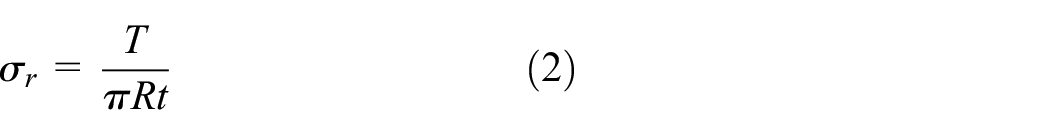
where T is the tension applied at point O, and t is the thickness of the membrane structure. A circular path passes through points O and P, with the radius of the circle being R. Using the relation
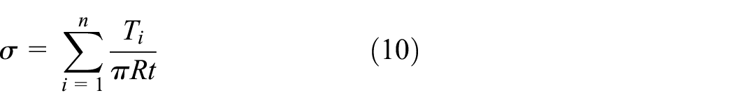
The radial stress is a constant on a circle with radius R; Figure 3 shows the stress contours of the radial stress

Airy stress function for membrane problem.

Radial stress contours.
Stress field of a circular membrane structure
We consider a circular membrane structure with n radial tensions

Equation (3) can be decomposed in X and Y directions as

where

Stress calculation by the coordinate rotation: (a) a circular membrane structure with n radial tensions and (b) the circular membrane structure after rotation.
Figure 4(a) shows that within the membrane structure there are the relations
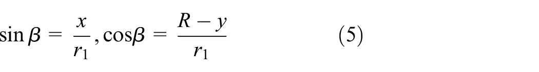
Substituting equations (4) and (5) into equation (3), the stresses in the X and Y directions at any point are written as
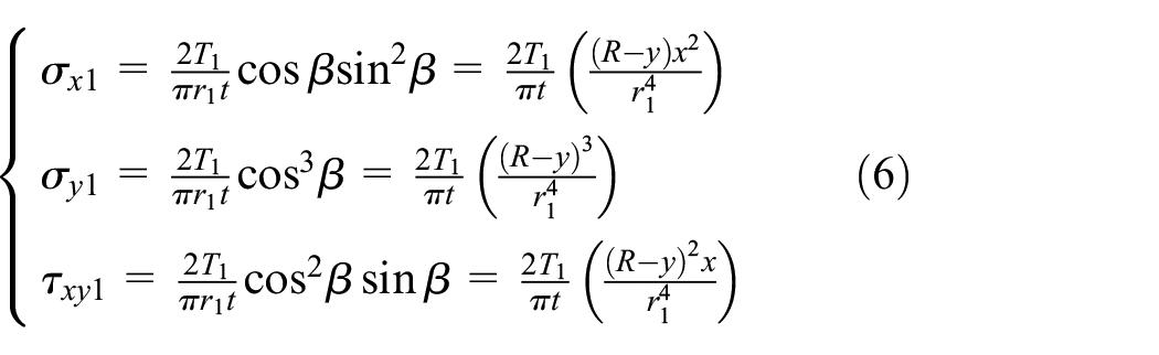
The stress generated by
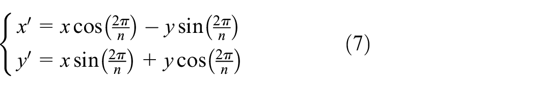
Substituting equation (7) into equation (6), the stresses at point Q generated by

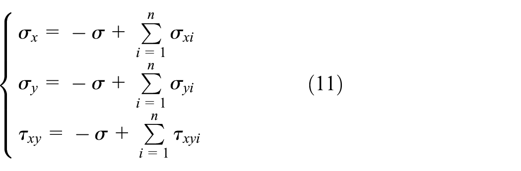
Similarly, the total stress at any point Q inside the membrane structure generated by all tensions is obtained as

Equation (9) is derived from equation (2) and is applicable to an infinite half space. However, a circular membrane structure is a free body and the stress outside the membrane structure should thus be zero. The stresses around the perimeter of the circle need to be calculated to counteract the edge effect.
On the basis of equation (2), the radial stress around the perimeter of the circle membrane is
Considering the edge effect, a compressive stress
Stress field of a square membrane structure
Figure 5 shows a square membrane structure with four radial tensions

For the vertical tensions, the radial stress is a constant on the inscribed circle having radius Rm. The stress generated by the vertical tensions can be calculated through coordinate translation as shown in Figure 6(b), where

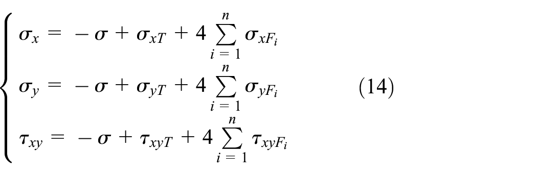
Considering the edge effect, the total stresses generated by all tensions are

A square membrane structure with both radial tensions and vertical tensions.

Square membrane structure: (a) membrane structure with only radial tensions; (b) membrane structure with only vertical tensions.
Simulation results
For a circular membrane structure with radius R = 300 mm, which is stressed by six equal radial tensions, T = 3 N. The analytical stress result is shown in Figure 7(a). For the same loading, finite element software ANSYS is used in linear stress analysis; the first principal stress field is shown in Figure 7(b). The analytical result compares well with the FEA result in terms of shape and magnitude. The local enlargement in Figure 7(a) shows that the areas between two loading portions and near the boundary are weakly tensioned, whereas areas closer to the loading points are highly tensioned.

The first principal stress field: (a) analytical result; (b) FEA result.
Figure 8 shows the second principal stress field. The local enlargement shows the second principal stress

The second principal stress field: (a) analytical result; (b) FEA result.
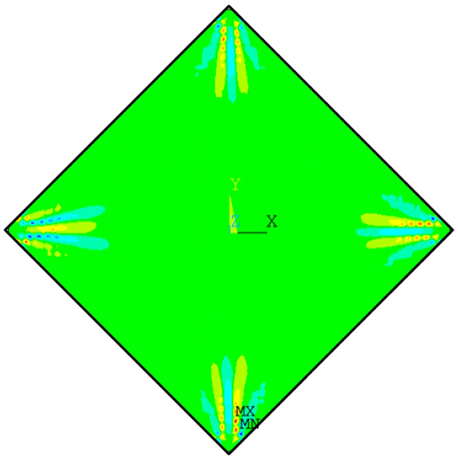
We consider the case of a square membrane structure that has a side length of 500 mm and is stressed by four radial tensions,

Analytical results: (a) the first principal stress field; (b) the second principal stress field; (c) the negative second principal stress.
Considering the effect of wrinkling, the initial wrinkling shown in Figure 10 is introduced into the finite element model, and the stress fields of the wrinkled membrane structure shown in Figure 11 are obtained employing the nonlinear buckling finite element method. The analytical results are closer to the FEA results, which further validates the analytical model.
Initial wrinkling.

FEA results: (a) the first principal stress field; (b) the second principal stress field.
In order to have in-plane stresses more evenly distributed, vertical tensions around the boundary are applied to the membrane structure, where

Stress field: (a) the first principal stress field (
Membrane shape design for the reduction of wrinkling
Design of the boundary shape
The removal of some areas of low-stress has been confirmed as an effective method of diminishing wrinkling regions, and a boundary cable is used to ensure that the membrane tension is uniform. Figure 13 shows the fundamental circular boundary shape with tensions, Tr, applied in the tangent direction of the cable. It is assumed that no shear is transferred between the cable and membrane. For the circular edge, the loads are equal and locally perpendicular to the edge, q represents the magnitude of the uniform loads, the boundary stress of membrane is expressed as

Circle boundary shape.
For the square membrane structure with a side length of 500 mm as shown in Figure 11, the boundary is trimmed into circular arcs stretched with the cable shown in Figure 14. The diagonals are tangent to the circles near the vertices, and the radius of circle arcs is

Arc-edge membrane structure.
Simulation results
We use finite element software ANSYS for linear stress analysis, SHELL181 elements are used to model the membrane. Tensions

Stress field: (a) the first principal stress field (

Weakly tensioned areas.
Conclusion
The Airy stress model was introduced to accurately estimate the stress field of a membrane structure. The first and second principal stresses were obtained through coordinate transformation. It was obvious that the areas between two loading portions and near the boundary were weakly tensioned, and regions of wrinkling with negative principal stress were estimated. To have stresses more evenly distributed, vertical tensions along sides were applied along the sides of a square membrane structure, and the ratio of the wrinkling area to the total area reduced from 33.5% to 20.3%. On this foundation, the arc-edge membrane structure was designed. Simulation results showed that the ratio of the wrinkling area to the total area dropped to approximately 4.5%. However, the optimal boundary shape was not analyzed in this article, and we will study a simpler and more effective optimization method based on an analytical stress model in future work.
Footnotes
Handling Editor: Ahsan Mian
Declaration of conflicting interests
The author(s) declared no potential conflicts of interest with respect to the research, authorship, and/or publication of this article.
Funding
The author(s) disclosed receipt of the following financial support for the research, authorship, and/or publication of this article: The project was supported by Natural Science Basic Research Plan in Shaanxi Province of China (Program No. 2019JQ-179). Scientific research program was funded by Shaanxi Provincial Education Department of China (Program No. 19JK0034).