
Abstract
Due to much lower cost of development and production, circular arc blades are often applied to axial flow fans. However, compared with NACA 65 profile, circular arc blades have higher losses, which are caused by the formation of separation bubbles or complete separation at the leading edge. Therefore, it is necessary to identify a specific geometry of leading edge, which can reduce the separation bubbles or complete separation. In this article, circular arc blades with different leading edges are examined by numerical method. The numerical investigations were performed with Reynolds numbers of
Keywords
Introduction
Due to the resource shortage, many blade profiles have been designed and tested to develop a blade with high efficiency, for example, the well proven and explored NACA profiles (National Advisory Committee for Aeronautics). 1 NACA profiles can provide good functionality and performance, but their development and production are also very expensive. In order to reduce the manufacturing costs, an alternative approach is circular arc blade. However, the flow losses of circular arc blade is higher than NACA 65 profile. Therefore, it is necessary to find a way to reduce the flow losses of circular arc blade by investigating the flow structure, aerodynamic quality values, and different profile geometries.
Generally, the losses of a turbine blade can be divided into profile loss and secondary flow loss. The profile loss is caused by the growth of the boundary layer on the blade and the formation of separation bubbles. The secondary flow loss is caused by the friction of the blade and sidewall. Therefore, in this article, the flow behavior such as secondary flow and separation bubbles are investigated.
Secondary flow
In 1980, Langston 2 was the first to illustrate a secondary flow model for two-dimensional (2D) boundary layer along the sidewall. In the present days, the researches about secondary flow are focusing on how to reduce secondary flow and the corresponding influence of the induced conditions on the secondary flow. Zess and Thole 3 tried to use a leading edge fillet to eliminate the horseshoe vortex at the leading edge of a turbine cascade. Liu et al. 4 and Zander and Nitsche 5 equipped synthetic jet actuators on the suction surface of a compressor cascade and investigated their influence on the secondary flow. Hermanson and Thole 6 and Chen et al. 7 studied the inflow variations (including inflow velocity, inlet boundary layer thickness, and inflow turbulence intensity) which affect the secondary flow behavior of a turbine cascade. Additionally, secondary flow is also normal in turbomachine, which reduces the energy performance and induces operation instability.8,9
K Liesner et al. 10 studied four different types of sidewall with suction slots and found out that with the reduction of the secondary flow, the total loss of compressor cascade can be significantly decreased. YC Nho et al. 11 determined that the cascade geometry can affect the secondary flow. Based on experimental and numerical investigations, HM El-Batsh 12 studied the secondary flow of an annular turbine cascade, and his study shows that the secondary flow is affected by the pressure gradient along blade span. In his case, the secondary flow near the hub was stronger than near the shroud, and the losses were concentrated near the hub.
In conclusion, the results about secondary flow can be written as follows:
Secondary flow is concentrated in blade–sidewall juncture. So, attempts of reducing secondary flow can take place in this region.
Secondary flow can be effected by inlet variations such as blade geometry, incidence, and Reynolds number.
Separation bubbles
Separation bubbles at the leading edge of blades are a challenging task of aerodynamics, and the behavior of separation bubbles have been examined by several authors with both numerical and experimental investigations. In 1963, Gaster 13 researched systematically the behavior of separation bubbles. Using a low-speed water tunnel, Courtine and Spohn 14 examined the separation bubbles for a constant flow over a generic bluff body with different front edge radii. Lamballais et al. 15 studied the formation of the separation bubbles over a generic half body with a rounded edge based on Reynolds number of Re = 1250. His work determined the combined effects of curvature and aspect ratio on the separation bubbles.
Shyy et al.
16
and Diwan and Ramesh
17
found out that the variation of Reynolds number and attack angle has a significant effect on the length and height of separation bubbles. Using advanced laser anemometry techniques, Crompton and Barrett
18
investigated the structure of the separation bubbles behind the sharp leading edge of a flat plate at Reynolds number from
Hamakhan and Korakianitis 19 and Zhang et al. 20 have changed the leading edge shape of Hodson–Dominy blade to investigate the influence of leading edge on the flow behavior and find a leading edge shape which can reduce the separation bubbles. SCT Perkins and AD Henderson 21 tested the influence of Reynolds number and incidence on boundary layer development at the leading edge of a blade. His work shows that the length of separation bubbles seems to reduce with the increasing Reynolds number. By the investigation of the cascades with circular leading edge and elliptic leading edge, Liu et al. 22 and APS Wheeler et al. 23 studied the influence of leading edge geometry on separation bubbles behavior. Their works show that the leading edge shape has a large influence on the formation of separation bubbles.
The results of the investigations about separation bubbles so far can be stated as follows:
The leading edge geometry, attack angle, and Reynolds number can affect the separation bubbles structure.
Usually, the length of separation bubbles decreases with the increasing Reynolds number.
Separation bubbles have a significant influence on the blade aerodynamic performance.
Circular arc blade
Most researches about circular arc blade are based on theory of Weinig,
24
who has developed an analytical theory based on potential flow for cascades consisting of thin-cambered blades. JB McDevitt et al.
25
have examined the transonic flow around a circular arc blade with Reynolds number from
A comparison between NACA 65 profile and circular arc blade for different spacing ratios, Reynolds numbers and incidences has already been made, and it can be stated that the main reason of the higher losses of circular arc blade is the separation bubbles induced by the leading edge of the blade. Therefore, the further research intends to find a leading edge geometry of circular arc blade, which can reduce separation bubbles.
In order to achieve this purpose, in this article, circular arc blade with different leading edges is examined by numerical method. The aims of this article are the following:
Investigate and compare the flow loss of circular arc blade with different leading edges based on 3D CFD simulations.
Identify a suitable leading edge geometry of circular arc blade, which can reduce separation bubbles.
Compare the flow structure and streamline of circular arc blade with different leading edges.
Show the flow loss in the sidewall region of the investigated blades.
The investigated blades
In this article, the investigated blades are circular arc blade with constant thickness, that is,
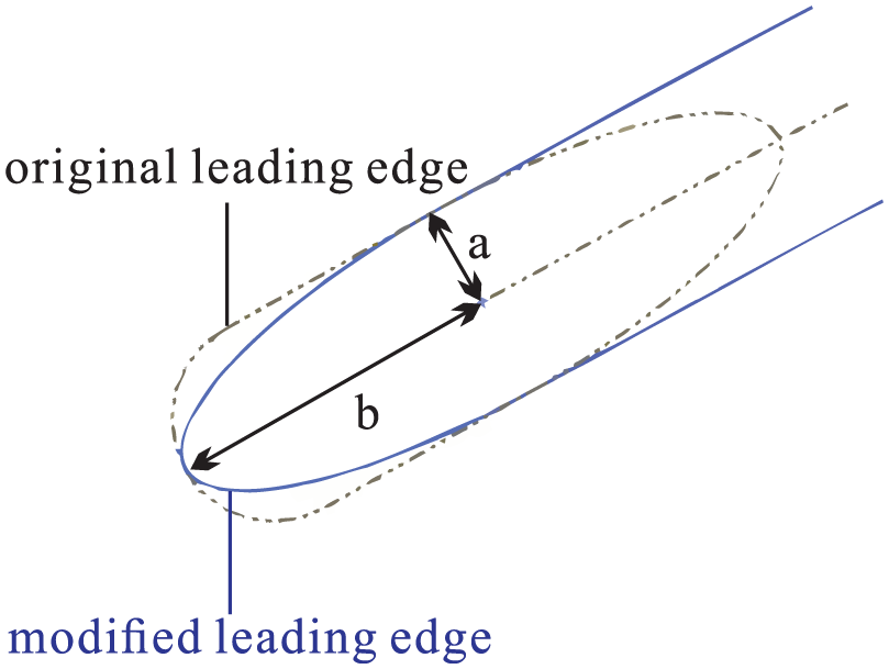
Geometry variation of leading edge.
In order to keep the thickness of all blades constant, the length of minor axis of the ellipse

The investigated blades: (a) blade-ori (
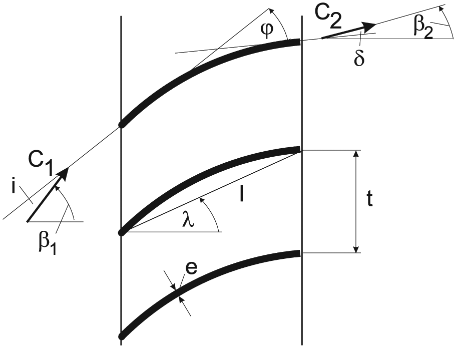
Nomenclature of investigated blades.
Parameters of used blades.

Numerical investigation
Three-dimensional (3D) flow domains were created for all blades with different leading edges. Using the software package Icem CFD from Ansys 15.0, the flow domains were discretized with block-structured grids. In order to determine the flow behavior of the boundary layers, the grids have been refined continuously toward the walls. The maximum spacing of the meshes to the walls is smaller than 0.02 mm, so that the

Grid detail: (a) grid detail on the leading edge and (b) grid detail on the trailing edge.

Flow domain with boundary condition.
The simulation were conducted with software Fluent 15.0. Reynolds-averaged Navier–Stokes (RANS) equations were solved on an unstructured grid. A second-order finite-volume-discretization was applied to a collocated grid. In this article, the flow behavior such as transition from laminar to turbulent boundary and bubbles separations must be considered, so the transition shear stress transport (SST) model was selected as turbulence model. The transition SST turbulence model is based on the coupling of the SST transport equations with the work of Menter et al., 28 who combines the SST-k-ω-turbulence model with empirical correlations for the calculation of the turbulent onset and the length of the transition region.
The numerical investigations are performed with Reynolds Numbers of

with
In order to consider the influence of boundary layer on the sidewall, the velocity profile of incoming flow has been investigated based on the free-flow measurement in the wind tunnel, which is used in the laboratory. These velocity profiles have been implemented in the inlet boundary conditions with a user-defined function (UDF). The used velocity profiles are depicted in Figures 6 and 7. Here,
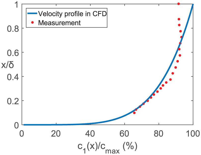
Velocity profile on inlet,

Velocity profile on inlet,
The turbulent intensity
Boundary conditions at each surface.

UDF: user-defined function.
In order to check whether the mesh resolution was sufficient, the grid was coarsened by doubling the mesh spacing within the wall regions. Three different meshes have been tested, and the results are depicted in Figure 8. It was determined that the coarsening of the mesh had no significant influence on the results.

Independence test of mesh number of blade-ori,
Experimental investigation
In this article, the experimental investigation for the original circular arc blade was conducted to guarantee the validation of the numerical results with the experimental measurements.
The measurement was conducted in a wind tunnel, which consists of an inlet nozzle, an axial compressor, a honeycomb rectifier, an acceleration nozzle, and a measuring section. The inlet nozzle has an inner diameter of 710 mm and a length of 1575 mm. Next to the inlet nozzle is an axial compressor, which is controlled by a frequency converter and has the power up to 37 kW. The honeycomb rectifier is used to reduce the swirled flow from the axial compressor by transferring it into a one-directional flow stream. After the honeycomb, the flow goes through the acceleration nozzle to reduce velocity differences and forms an uniform velocity distribution on the measuring section, which is located at the end of the wind tunnel (see Figure 9).

Wind tunnel.
The total and dynamic pressures of the incoming flow are measured by a Prandtl probe, which is located in the center of inflow section (see Figure 10). The pressures on the measuring plane are detected by the five-hole probe, which is mounted in the traverse system. This system consists of the step motors, which can move the five-hole probe in both x and y directions, thus with the computer control the five-hole sonde can measure the pressure of any point on the measuring plane.

Wind tunnel and measurement section.
Two side channel compressors are mounted on the top and bottom of the measuring section. The speed of the side channel compressors is controlled by a frequency converter. The task of both side channel compressors is to ensure that the boundary layers on the upper and lower wall are sucked away so that the flow in y-direction becomes periodic.
Results
Loss coefficient and turning angle
The dimensionless loss coefficient

with

with

Loss coefficient of original circular arc blade.
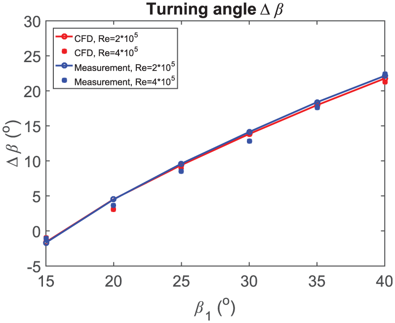
Turning angle of original circular arc blade.
As the results show, the
The dimensionless loss coefficient
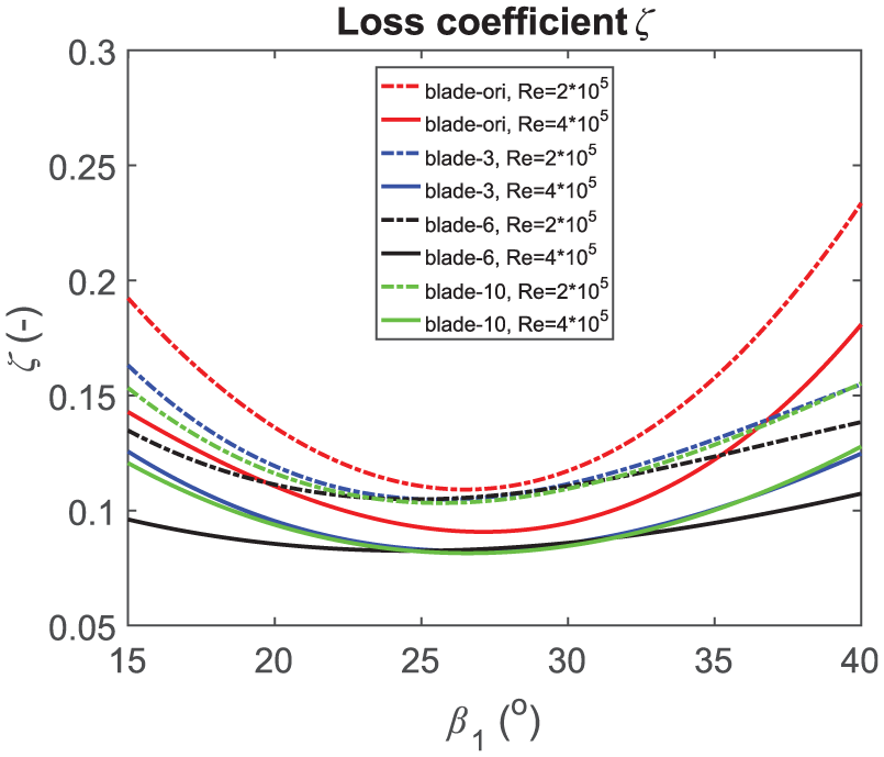
Loss coefficient of the blades with different leading edges.

Turning angle of the blades with different leading edges.
Separation bubbles
Due to an adverse pressure gradient, laminar boundary layer separates from the surface of the blade, then separation bubbles appear and the laminar flow transforms into turbulent flow. The separation bubbles occur usually at the leading edge of thin blades and can modify the flow structure of the blade and consequently have an influence on the blade aerodynamic performance.
The CFD simulation results of the separation bubbles at the leading edge of each blades are depicted in Figures 15–22. With an inflow angle of
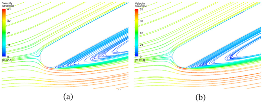
Separation bubbles of blade-ori,

Separation bubbles of blade-3,
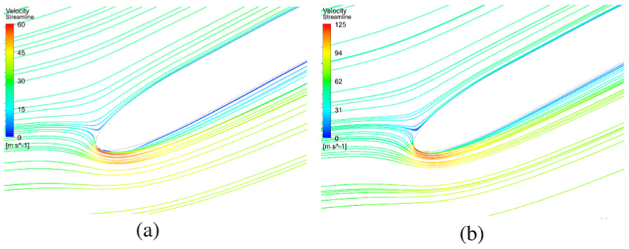
Separation bubbles of blade-6,
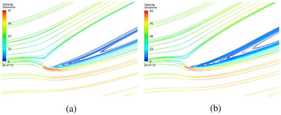
Separation bubbles of blade-10,

Separation bubbles of blade-ori,

Separation bubbles of blade-3,

Separation bubbles of blade-6,
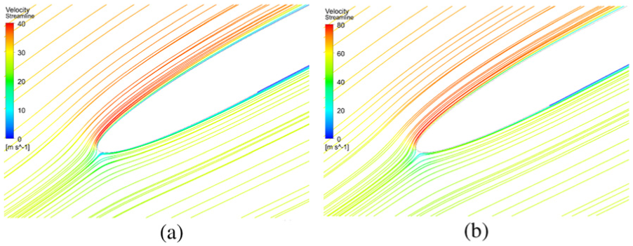
Separation bubbles of blade-10,
When
The length of separation bubbles decreases when Reynolds number is increasing. This result has a good agreement with SCT Perkins and AD Henderson,
21
who conducted the measurement of a blade with circular arc leading edge at Reynolds numbers of
Streamline on the sidewall
Besides the separation bubbles, secondary flow plays also an important role in the flow behavior of the blade. In Figures 23–26, the flow structure (near the sidewall) of each blade are depicted.

Streamline of blade-ori,

Streamline of blade-3,
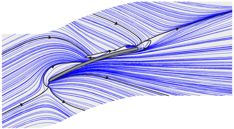
Streamline of blade-6,

Streamline of blade-10,
Due to the viscous effect of the flow and the friction on the sidewall, the flow velocity close to the wall is very small, thus the centrifugal force of the flow is reduced in this region. Since the static pressure is essentially the same in the boundary layer as it is in the adjacent outer flow, it is typical that streamline is curved within the boundary layer of the sidewall (on the sidewall).
The flow structure near the sidewall of all investigated blades is similar. At the inlet area, the streamline flows parallel toward to the blade with the given incidence. When the inflow hits the saddle point near the leading edge of the blade, then the streamline separates into two parts. One part moves toward to the suction side of the blade under the influence of the secondary flow. The other part of the streamline turns and transforms into the secondary flow.
Loss distribution in the sidewall region
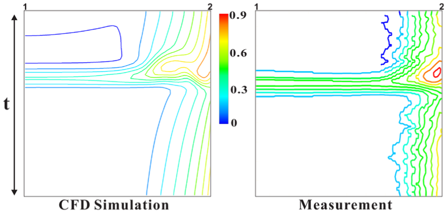
The ζ-distributions of all investigated blades are depicted in Figures 27–36. The ζ-distribution is investigated on the plane, which is parallel to the inflow plane and 50 mm downstream behind the trailing edge of the blade (see Figure 5). On the left side of the figures is the symmetry plane (which is marked as 1), and on the right side of the figures is the sidewall (which is marked as 2); the upper and lower sides of the figures are periodic boundary. Again the friction of the sidewall and the blade affects the inflow velocity, which leads to a lower velocity and therefore to a decrease in the total pressure. Furthermore, this leads to higher flow losses in the corner region between the blade and the corresponding sidewall.

Loss distribution on the measuring plan of blade-ori (original blade),

Loss distribution on the measuring plan of blade-ori,

Loss distribution on the measuring plan of blade-3,

Loss distribution on the measuring plan of blade-6,

Loss distribution on the measuring plan of blade-10,
Loss distribution on the measuring plan of blade-ori (original blade),

Loss distribution on the measuring plan of blade-ori,

Loss distribution on the measuring plan of blade-3,

Loss distribution on the measuring plan of blade-6,

Loss distribution on the measuring plan of blade-10,
Figures 27–33 show that the ζ-distribution of blade-ori of CFD simulation has a relative good agreement with the measurement results. With
When
At the higher Reynolds number, for example, Reynolds number =
Conclusion
In this article, circular arc blades with different leading edges are investigated by numerical method. The investigated blades in this work are applied in guide vane, so the flow losses and turning angle are tested. The main purpose of this article is to find a leading edge geometry of circular arc blade which can reduce separation bubbles and finally decrease the flow losses.
By changing the leading edge geometry of circular arc blade, the separation bubbles can be reduced and flow losses can be decreased. The blade-6 has the best performance of reducing separation bubbles and the lowest flow losses. Regarding of inflow angle
Except the formation of separation bubbles at the leading edge of the blade, the leading edge geometry has no significant influence on the flow structure near the sidewall. Generally, streamline turns in the region which is close to the sidewall. Due to the suitable leading edge, blade-6 has less separation bubbles than the other three blades. The length of separation bubbles increases with the decreasing Reynolds number.
The high flow losses are developed in the corner region between the blade and the corresponding sidewall. Because only small separation bubbles occur at the leading edge of blade-6, the wake behind the blade-6 is also smaller than the other three investigated blades. At the higher Reynolds number, the boundary layer on the blade and the corresponding sidewall is thinner and the flow loss in the corner region between them is lower. Therefore, the loss coefficient
The investigated circular arc blades in this work have a constant thickness. When the thickness is not constant, the separation point of the flow is different, so the flow structure and flow loss are also different.
Footnotes
Handling Editor: Roslinda Nazar
Declaration of conflicting interests
The author(s) declared no potential conflicts of interest with respect to the research, authorship, and/or publication of this article.
Funding
The author(s) received no financial support for the research, authorship, and/or publication of this article.