
Abstract
Within the Cluster of Excellence for Sustainable and Energy-Efficient Aviation SE2A, a blended wing body aircraft is investigated to improve efficiency and carbon emissions of future air transport. By embedding the aircraft engines on the top rear fuselage, parts of the aircraft’s wing boundary layer are ingested, which has the potential to further improve the engine’s propulsion efficiency. Through the ingestion of low momentum fluid, inflow distortion is induced and the fan rotor operates under increased flow incidence, when passing through the distorted flow regimes. To reduce the thereby arising efficiency and pressure ratio penalties in the aircraft engine, alternative design strategies for the fan stage are required. Within this investigation, an active shape morphing mechanism is introduced, which allows to temporarily adjust the fan blading when the fan rotor is exposed to distorted inflow conditions. By integrating piezoceramic actuators into the rotor blading, the blade staggering and turning can be adjusted with the goal to reduce flow incidence and deviation in the distorted flow regimes. For this investigation, the NASA rotor 67 is chosen as an initial test case and its performance under boundary layer ingestion (BLI) conditions is evaluated. For the shape morphing assessment, FEA morphing simulations are coupled with stationary CFD simulations of the actuated fan rotor geometries under distorted inflow. As the achievable deformations for the NASA rotor 67 are however too small to compensate for the strong distortion effects, a fan re-design is conducted. The re-design follows current ultra-high-bypass-ratio (UHBR) fan concepts with a particular focus on the shape-morphing capability of the rotor. Within this investigation the focus especially lies on three-dimensional design adaptions, such as a hub chord reduction as well as dihedral and sweep. By considering carbon fiber reinforced polymers (CFRP) as blade material, the impact of tailored blade architectures on the morphing behavior is additionally considered.
1. Introduction
To increase the energy efficiency of future air transport, new aircraft architectures are investigated. Here, boundary layer ingestion (BLI) is a promising concept to improve overall efficiency. The ingestion of the aircraft structure’s boundary layer allows to improve the propulsive efficiency by exploiting the reduced inflow momentum at the engine intake, (Smith, 2023). Within the Cluster of Excellence for Sustainable and Energy-Efficient Aviation SE2A, a blended wing body aircraft featuring engines embedded on the top rear fuselage is currently researched (Figure 1). The ingestion of low momentum fluid leads to distortion effects in the lower shroud area of the intake. When passing through areas of different flow conditions, the fan experiences flow incidence and instationary aerodynamic effects, which indicates a major drawback of BLI concepts. The dominant inflow condition in the distorted area differ from those of the rotor design point. Especially for modern transonic compressor rotors with an increased tip loading inflow incidence may diminish the BLI benefits through increased losses in the fan stage (Giesecke and Friedrichs, 2019). To align both BLI effects on the overall propulsion efficiency, this research investigates the concept of a shape-adaptive rotor. Adding piezoelectic Macro Fiber Composite™Actuators (MFC) to the blade architecture allows to morph the blade’s shape depending on the circumferential position of the rotor (Figure 1). While passing the distorted flow regime, the piezoelectric actuators provoke a specific adaption of the span-wise blade twist and cambering, according to the prevalent flow angle variations induced by the low momentum fluid. With the highest achievable deformations located toward the rotor tip (Seidler et al., 2022), the shape-adaption concept increases the design flexibility where the highest aerodynamic effects of inflow distortion are expected. Based on generic distortion patterns, this research aims to mitigate the drawbacks of inlet distortion through deriving a suitable actuation concept for the distorted flow regimes. First, the transonic NASA rotor 67 (Hathaway, 1986) is transformed into a shape-adaptive system, as previously described by Seidler et al. (2022). As the applied MFC actuators allow for actuation frequencies up to 10 kHz (Smart Material GmbH, 2023), an actuation once per rotation is technically feasible for high-speed fan rotors, such as the chosen test case. For design speed, the blades of the NASA rotor 67 would pass the distorted flow regimes with 267 Hz (Hathaway, 1986), determining the required actuation frequency. Modern UHBR turbofans, which would be employed in BLI engines, require even lower actuation frequencies in the range of 50 s−1 (Giesecke and Friedrichs, 2019). By investigating the effects of BLI on the stage performance, actuation strategies are specified and a structural morphing assessment for different actuation concepts is carried out. To evaluate the potential of the feasible shape variations, representative stationary CFD simulations are conducted for a rotor and stator passage with maximum distortion.
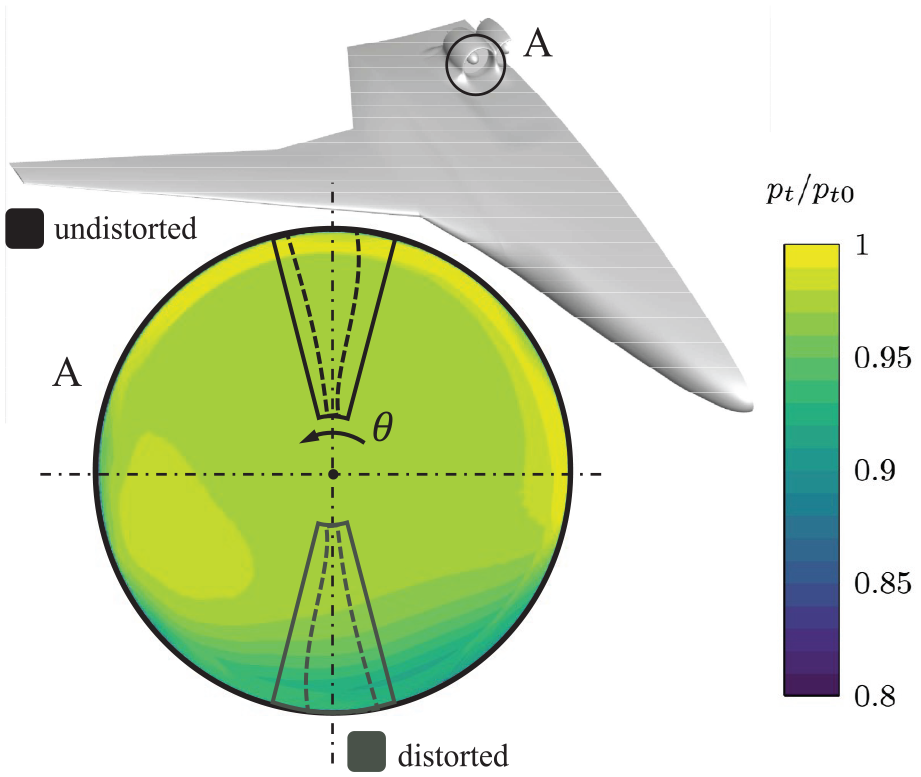
BWB half model with total pressure distortion pattern upstream of the fan due to boundary layer ingestion.
The initial findings are consequently transferred to the geometry of a scaled turbofan rotor with main dimensions comparable to current UHBR fan designs (Seidler et al., 2024a). The rotor reference design is consequently varied to increase its morphing potential and thus the achievable impact on the fan stage performance under distorted inflow conditions. This design study focuses on three-dimensional design adaptions, such as a hub chord length reduction and the application of sweep and dihedral. Alternative blade materials are also considered. While the initial morphing investigations are conducted with titanium alloy blades, the application of carbon fiber reinforced polymers (CFRP) allows for a tailored blade architecture. By optimizing the orthotropic material properties induced by the orientation of the carbon fiber material, the tailored CFRP blade supports the deformability toward a piezoelectric actuation while withstanding the high centrifugal loads during operation. With that, this study aims to investigate piezoactive rotor blading as an alternative to pitch-variable fan blading (Mennicken et al., 2022), variable nozzle geometries (Hall and Crichton, 2006) or an adaption of the stator geometry (Giesecke, 2022) to mitigate BLI induced off-design drawbacks. In comparison, piezoelectric actuation concepts inherit a lower mechanical complexity and weight, while offering the means to individually control the voltage supply for single blades and fractions of the full rotor annulus. Despite remarkable achievements for the active morphing of aircraft wings (Barbarino et al., 2014), wind turbine blades (Krawczyk et al., 2013) as well as simplified stator cascades (Abate and Riemenschneider, 2025), an application of piezoelectric actuators to the complex three-dimensionally shaped blades of a turbofan rotor has so far not been conducted. Suman et al. (2017) experimentally applied Shape Memory Alloy (SMA) actuators to the polymeric blades of an automotive cooler fan, thereby increasing its cambering and therefore the loading coefficient, especially during part-load operation. In a numerical approach, Tweedt (2013) investigated the impact of twist adaptive UHBR turbofan blades on the operating range and efficiency of two fan rotor geometries. Although the deformations were assumed to be variable in span-wise direction, no actuation concept was specified. A positive effect on the surge margin during take-off conditions was however observed, indicating the potential of piezoelectric fan blading for an overall higher propulsive efficiency throughout the flight mission. The positive effect of a piezoactive fan on the overall fuel consumption during different flight missions was later confirmed by Seidler et al. (2024b) through mission-based thermodynamic cycle calculations. The specific effect of piezoelectrically deformed blade profiles on the blade-shock interaction of pre-compression blade profiles is reported in Li et al. (2023). Here, the choking behavior of a simplified 2D cascade was altered by piezoelectrically controlling the pre-compression strength of the profile section investigated. Within the research presented, a numerical model of an established actuation concept (Krone et al., 2017) is therefore combined with state-of-the art fan rotor geometries. Thereby the comprehensive efforts of the authors to evaluate aerodynamic losses due to boundary layer ingestion (Voigt and Friedrichs, 2021) and the transformation of conventional fan geometries into shape-adaptive systems for an increased off-design efficiency (Seidler et al., 2022) are consolidated.
2. Methodology
2.1. Derivation of the distortion pattern
To generate an authentic BLI distortion pattern, compressible, steady state 3D-RANS simulations of the SE2A blended wing body (BWB, Figure 1) reference design were conducted. The aircraft geometry and flight conditions are based on design studies carried out for the next design iteration of the BWB, as described in Karpuk et al. (2020). Nacelles designed following the methodology described in Benjamin et al. (2020) were integrated onto the top rear of the aircraft fuselage. The DLR TAU-Code (Schwamborn et al., 2006), a finite-volume-based Navier-Stokes solver, is used for the CFD simulation, while the mesh is generated with CENTAUR. The mesh is unstructured except for prism layers in the near-wall regions. For turbulence modeling, the k-
2.2. Stage performance evaluation
To evaluate the aerodynamic performance of the fan stage, 3D steady-state passage simulations are conducted in Ansys CFX. For the rotor and stator domain with one blade each, a structured mesh is created with
The dimensionless wall distance
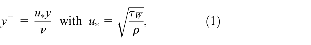
with the friction velocity
2.3. Structural morphing methodology
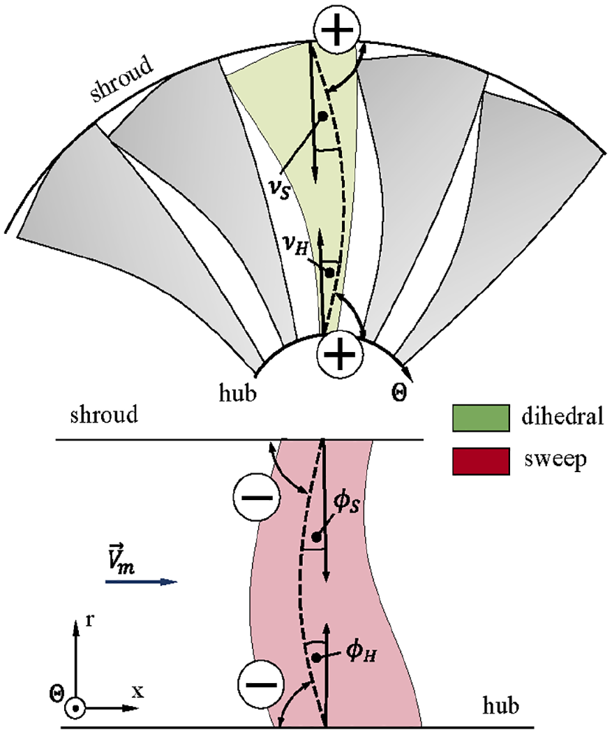
Mitigating the BLI induced drawbacks requires a specific variation of the span-wise blade angles. After these requirements are derived from the CFD results, an angular optimization target for the structural design methodology is defined. For the structural morphing simulation, the blade and actuator geometries need to be created. Here, the blade sections of the reference blade geometry are used to derive a 3D CAD model of the rotor (see Figure 2). These sections also serve as a reference for the definition of the actuators, which are applied onto the suction (SS) and pressure side (PS) of the blade (see Figure 2). The actuators extend over the entire blade span, while in chord-wise direction the actuator dimensions are defined as a fraction of the blade chord l. The maximum chord-wise extent of the actuators is determined by the minimum blade thickness that would be required for an integration of the actuators into the blade architecture. As the profile sections become thinnest at the blade tip, it is the tip section design that determines the feasible actuator length in chord-wise direction.
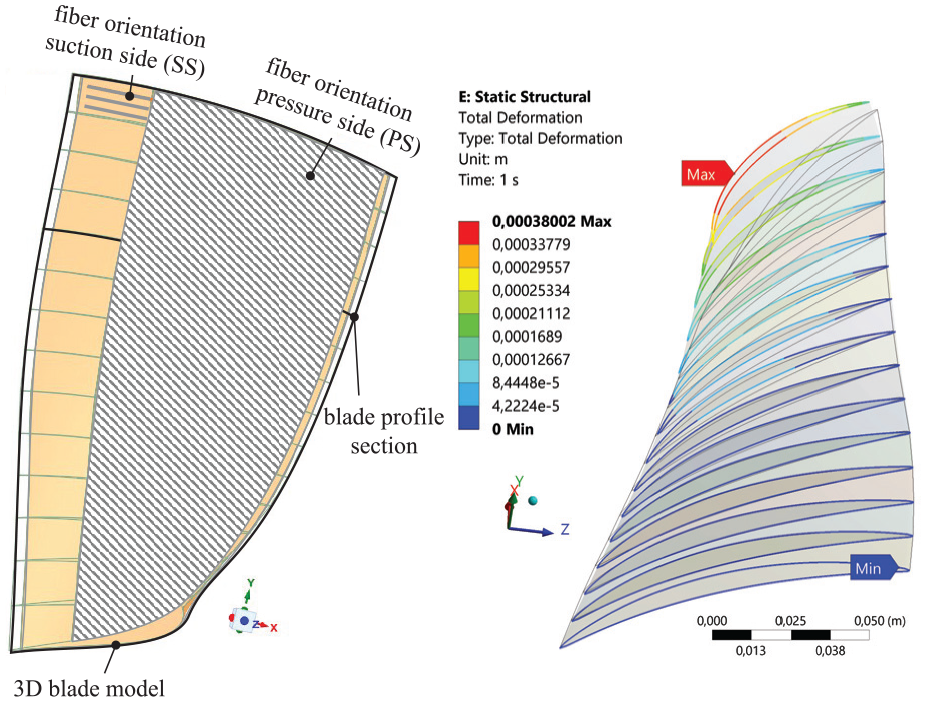
Actuator models based on blade reference sections (left) and simulated deformations at the blade sections (right).
After creating 3D models of the blade and actuator geometries, material properties are assigned. In the structural model, the piezoelectric actuators are implemented as MFC actuators, which consist of expanding/contracting piezoceramic fibers (Smart Material GmbH, 2023). Depending on the aerodynamic morphing target suitable piezoceramic fiber orientations are specified for the MFC actuators, which together with the actuator dimensions and the actuation mechanism determines the deformation behavior of the blade. The blade body can either be designed as a full titanium rotor or as a composite structure. Both materials are investigated in this research. For the composite structure, carbon fiber reinforced polymers are applied. Within this investigation, layers of Epoxy Carbon UD (230 GPa) prepreg and Epoxy Carbon Woven (230 GPa) prepreg are used in combination with Resin Epoxy as the drop-off and cut-off material (Ansys Inc, 2022b). The CFRP blade additionally exhibits an optional foam core (San Foam, 103 kg m−3). For the modeling of the blade’s laminate structure in Ansys Composite PrepPost (ACP), surface models are required as an input. Therefore, surface meshes of the blade’s suction and pressure side are created instead of a fully meshed 3D volume model. Starting from the meshed surfaces, the layers of the laminate are defined, which results in two blade halves. To prevent an overlapping between the blade halves, the layers are cut at a mid-surface, which is defined by the blade sections’ camber lines (see Figure 3). The resulting model is composed of shell elements that are transformed into solid elements for the finite element analysis (FEA). In Ansys ACP, this conversion is executed by extruding from the meshed surfaces of the suction and pressure sides. Accompanied by guided extrusions in the root and tip areas and an adaptation to the mid-surface, the outcome is a solid model that is devoid of overlaps, gaps or offsets. The blade halves are joined utilizing a contact bonding approach. In case an isotropic material like titanium is used, an unstructured 3D mesh is used for the 3D blade geometry. After the structural models are created for the actuators and the blade body (composite or isotropic), the actuators are placed onto the blade surface. To transfer the deformations from the actuators into the blade’s structure, a contact bonding approach between actuators and blade is applied, which also results in combined load bearing between the components. The definition of boundary conditions provides the final step for the structural model (Figure 3), from which then the morphing can be calculated.
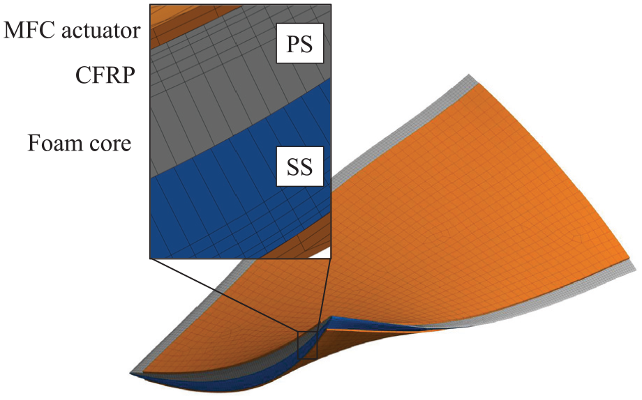
Layers and composition of the structural CFRP model with MFC actuators.
During the preliminary experimental investigations, conducted by Krone et al. (2017) an electric field was exploited to evoke the shape variation of the MFC actuators. In the structural methodology presented, the actuator’s behavior is approximated with a thermal expansion analogy, as described by Kovalovs et al. (2007) and later applied in Kleinwechter et al. (2024). The analogy approximates the deformation that would normally be reached through the introduction of the electric field by defining suitable thermal boundary conditions. To consider the risk of actuator damage due to the centrifugal pre-loading and a maximization of the actuation voltage the applied voltage is limited to
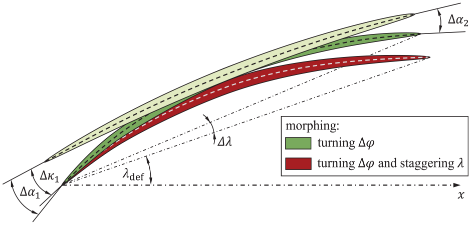
Schematic blade section morphing with angular variations.
The structural morphing results are therefore exported for the aerodynamic design sections. As displayed in Figure 4, an extensive post processing routine transforms the directional displacement for every mesh node into a span-wise aerodynamic blade angle morphing, such as the variation of the leading edge metal angle

with

where def refers to the morphed shape and ref to the blade angles of the reference geometry. The variation of the blade turning is calculated as follows:

With that, a positive angular morphing value corresponds to an increase compared to its original value.
2.4. Blade design
For the turbofan design and its variants, streamline curvature (SLC) design calculations are conducted, following the methodology described in Seidler et al. (2024a). By choosing a span-wise load distribution for the rotor, the SLC procedure allows to estimate the meridional distribution of relevant flow quantities, defining the inflow as well as outflow angles of the rotor. Based on those, a suitable rotor geometry is derived and transferred to the structural morphing analysis. An efficiency evaluation based on Bullock and Johnson (1965) and Cunnan et al. (1978) allows to assess the enthalpy rise through the rotor and to iterate the required design pressure ratio for a pre-selected mass flow. The profile sections are defined with an equal spacing in span-wise direction. The main dimensions that determine the meridional shape of the blade, are the hub-to-tip ratio
For the implementation of sweep and dihedral, the sweep (
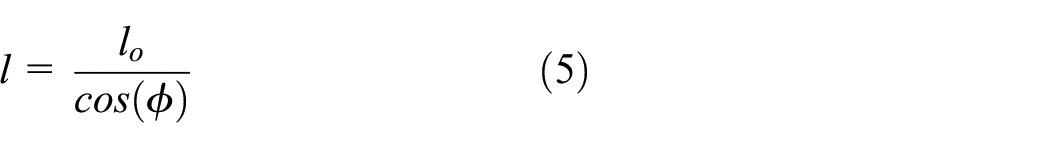
Schematic visualization of the sweep and dihedral angles, defined for the stacking line of the rotor (dashed).
This correlation is well known from aircraft wing design and has been applied in previous research (Eggers et al., 2020; Giesecke and Friedrichs, 2019). Thereby the sweep effect on the span-wise load distribution is mitigated and the aerodynamic designs remain comparable within this investigation.
3. Results
3.1. Impact of BLI on stage performance
Three speed lines at 100%, 85%, and 70% design speed are evaluated for undistorted flow conditions (black) and a distorted blade passage (gray; Figure 1). In Figure 6 the isentropic efficiency
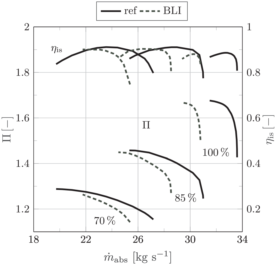
Performance of the reference NASA rotor 67 with upstream distortion (gray) and undistorted inflow (black).
Through the total pressure deficit upstream of the rotor, the required rotor work input increases. The blade loading is elevated, especially affecting the tip region, where the distortion effects are most prominent. Ingesting the boundary layer of the blended wing body’s fuselage reduces the meridional velocity toward the fan. Thereby, the mass flow over all speed lines is decreased. Combined with a constant rotational speed, the relative inflow angle is raised, causing flow incidence, which becomes especially critical under part-load operating conditions. Under distorted inflow conditions, the characteristic increase in tip loading during part-load becomes more critical, which results in the surge margin reduction for all speed lines displayed in Figure 6. The deficit in design point mass flow is highest for the 100% speed line, as the rotor performance is highly sensitive toward the unique incidence condition. Although the inlet distortion reduces the relative inflow Mach number, the flow remains transonic in the outer span of the rotor. With a passage shock occurring in the upper flow regimes of the rotor, BLI mainly affects the unique incidence condition and its characteristic mass flow. With that, flow separation within the blade passage is mainly driven by the strength and position of the passage shock. A similar effect is visible for the right branch of the 85% speed line, where the dependency on the unique incidence condition accelerates the mass flow deficit. With a further reduction of the mass flow a reduced percentage of the rotor operates under the unique incidence condition. With that the rotor performance is increasingly affected through a steeper inflow and the earlier onset of flow separation in the blade passage. The combination of raised blade loading and earlier flow separation are also the dominant effects for the 70% speed line, where the reduction in surge margin is strongest. A significant passage shock only occurs in the upper 15% of the rotor, when the stage operates close to its choke limit. This leads to the higher mass flow deficit toward increased operating mass flow rates. For all speed lines the achievable peak efficiency is reduced, when operating under distorted inflow conditions. With 1.15% the efficiency deficit is highest for the 70% speed line, driven by the increased flow incidence. For higher relative inflow Mach numbers, the BLI effect is dampened by the occurrence of a passage shock resulting in a lower peak efficiency deficit of 0.65% for the 100% speed line (Figure 6).
3.2. Rotor morphing results
The drawbacks of BLI on the fan stage performance are driven by the flow incidence caused by the low momentum flow in the distorted regimes of the fan face. Neglecting the impact of the blade thickness and camber on the flow angles, flow incidence is caused or compensated by a variation of the leading edge metal angle:

To reduce flow incidence, two actuator configurations are derived that temporarily allow to increase the leading edge metal angle
Details of the actuator configurations applied.
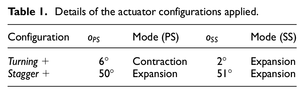
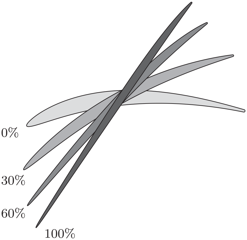
Figure 7 summarizes the achievable variation of the metal angle
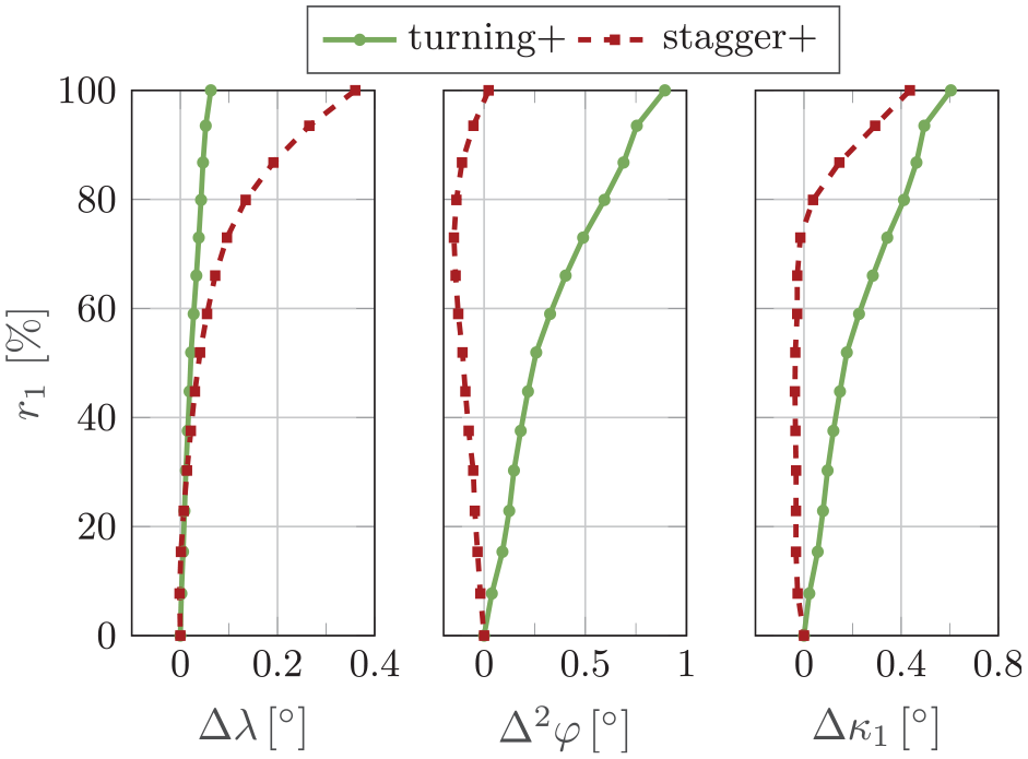
Achievable shape adaption for a stagger and a leading edge camber angle morphing.
Through the centered location of maximum thickness and camber position, an increase of the leading edge camber angle requires actuators that maximize the blade turning. With the orientation of the piezoelectric fibers in the MFC actuator determining the actuation direction and the cantilever of the forces applied into the blading, the structural design yields a piezoelectric fiber orientation that approximates the streamline slope of the tip section. This results in a MFC actuator fiber orientation of
3.3. Morphing effect on stage performance
A higher profile turning of the rotor (turning+) locally increases blade loading (Figure 8). During part-load operation, the characteristic load redistribution toward the blade tipis amplified, which elevates the overall pressure ratio
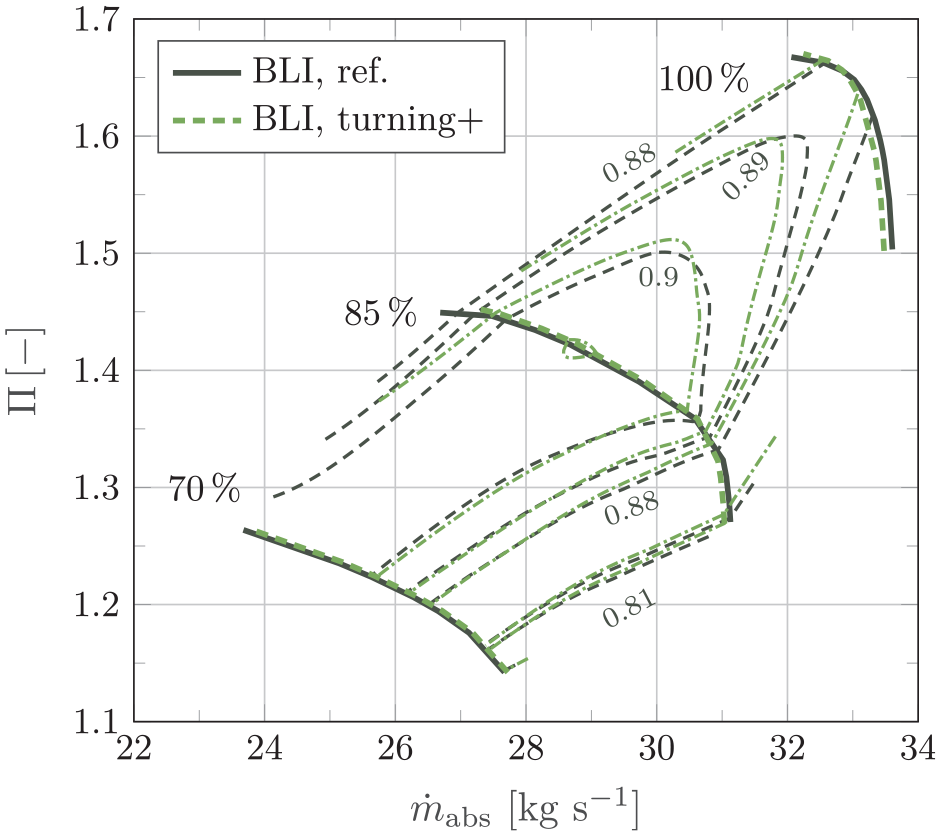
Effect of a blade turning morphing on the rotor performance under BLI influence, displayed for different rotational speeds and the efficiency iso lines.
An increase of the stagger angle (stagger+) constantly shifts the speed lines toward lower mass flow rates (Figure 9). The higher leading edge metal angle
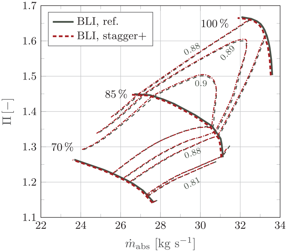
Effect of a blade stagger angle adaption on the rotor performance under BLI influence, displayed for different rotational speeds and the efficiency islands.
3.4. Design of a shape-adaptive fan stage
The chosen NASA rotor 67 test case is therefore substituted by a design, that follows recent UHBR fan design trends. Following Seidler et al. (2024a), a scaled rotor design is chosen, which potentially allows a subsequent test rig application. The potential test rig application defines the maximum fan diameter and yields a hub-to-tip ratio
Blade profile sections at different rotor heights.
Although the improvement potential for a shape-adaptive fan stage under BLI conditions became apparent, the achievable deformations are too small to significantly alter the drawbacks of ingesting low momentum fluid. With the actuator strength being limited, the blade shape and material remain as design parameters for increasing the shape morphing potential. For the re-design of the blade geometry, especially 3D-design measures are considered as an approach to improve its morphing behavior. Within this investigation, five design parameters are introduced: the hub chord length
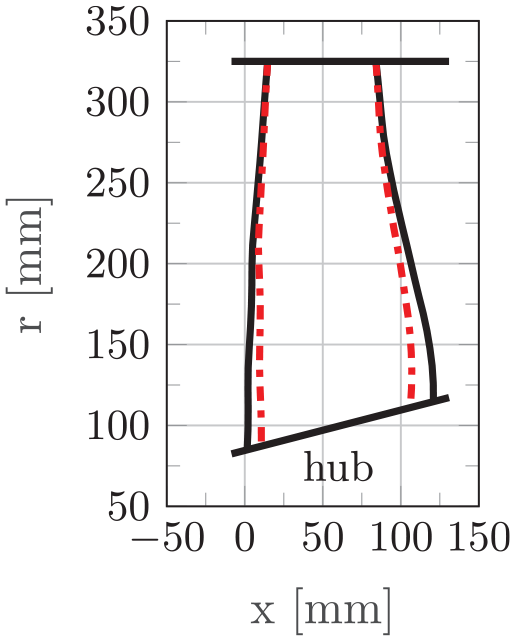
Meridional view of the fan rotor design (black: reference, red: fan design with reduced hub chord length).
For all design alterations, both actuator configurations from Table 1 are applied, keeping the respective fiber orientation, actuation mechanism and relative actuator dimensions constant. With that constraint, the actuator length is adjusted, depending on the design chord length of the rotor. In span-wise direction, the actuators continue to extend from hub to tip.
3.4.1. Hub chord length
A reduction of the hub chord length leads to a leaner blade shape toward the hub (Figure 11). In radial direction, the hub chord length transitions linearly into to tip chord, which remains constant compared to the blade reference design. To guarantee for the structural integrity of the blade even for reduced chord lengths and profile dimensions, the cross section area of the reference hub section is defined as a boundary condition. Adapting the chord length therefore requires an adjustment of the profile thickness parameters until a similar cross-section area is maintained. Within this investigation, the chord lengths are adjusted between 80% and 110% of its original reference length.
3.4.2. Application of sweep and dihedral
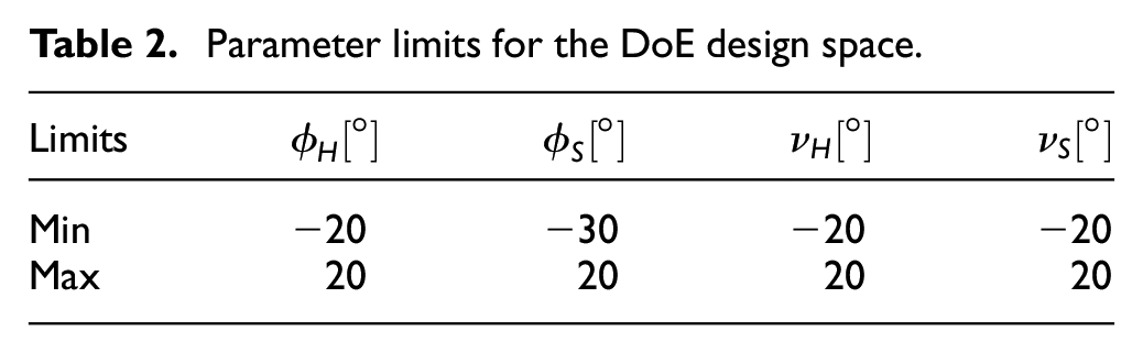
For the evaluation of randomized 3D-adapted blade shapes, a design of experiment (DoE) is conducted with 125 differing parameter combinations. Each design is based on the turbofan reference design and adapted according to the randomly chosen sweep (
Parameter limits for the DoE design space.
For the evaluation of the DoE results, the parameter correlations are considered according to the linear Bravais-Pearson correlation. Following Kronthaler (2014), the correlation analysis yields values between 1 and -1, where negative values indicate an inverse correlation, while correlation parameters below an absolute value of
3.4.3. CFRP blade design
In the structural design process of the CFRP blade architecture, the structural integrity of the blade acts as the primary design constraints. Therefore, a failure analysis is conducted, as the CFRP fan blade will be exposed to operational and morphing loads. One failure criterion employed is the Puck criterion (Puck, 1996), which distinguishes fiber failure, matrix failure, and delamination. Moreover, the maximum stress (MaxStress) and strain (MaxStrain) criteria of ACP (Ansys Inc, 2022a) are utilized to verify that the respective stress and strain components do not violate their thresholds. Based on an inverse reserve factor of less than 0.66, a laminate with the stacking sequence
3.5. Morphing potential of the fan re-design
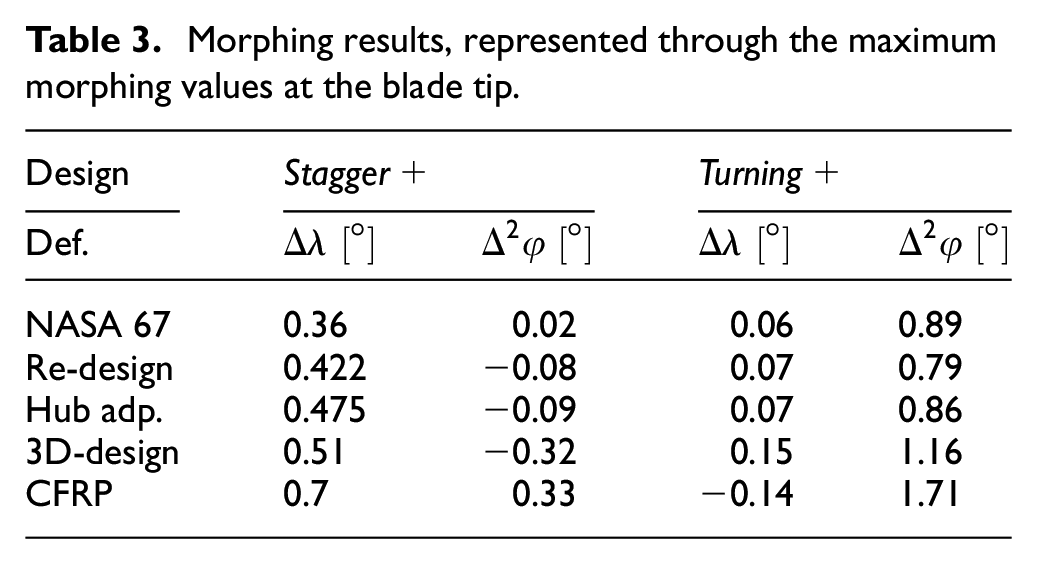
Both actuator configurations are applied to each reference design variation. The results are summarized in Table 3 and evaluated with respect to the operational requirements of the BLI off-design scenario. For each actuator configuration and rotor design the maximum stagger angle variation
Morphing results, represented through the maximum morphing values at the blade tip.
3.5.1. Impact of the fan re-design
Through the increased rotor span, the stagger angle morphing capability is elevated, while the turning morphing capability becomes smaller. For the stagger+ actuation, the actuation cantilever (length in fiber direction of the actuator) is increased, which elevates the achievable stagger morphing at the blade tip. While the stagger angle morphing capability is increased, morphing the blade turning becomes more difficult. The absolute chord length of the re-designed rotor increases compared to the NASA rotor 67. Although the actuator size becomes bigger, the increased blade chord length determines a higher absolute blade thickness due to structural integrity requirements. The actuators need to deform a stiffer geometry and therefore the blade’s resistance against a piezoelectric actuation is elevated. This reduces the deformability and therefore the turning morphing capability of the chosen turbofan design.
3.5.2. Impact of the hub chord length variation
By reducing the hub chord to 80% of its original length, the angular morphing for both actuator configurations is improved (Table 3).
As shown in Figure 12, a stagger+ actuation benefits from a reduction of the hub chord. This benefit becomes smaller when the thickness of the profile sections is adjusted according to the equal area requirement imposed by the structural integrity boundary condition (adp.). For the turning morphing capability (turning+) an adverse effect becomes apparent. A rotor design, where the blade thickness parameters are not adjusted (w.o. adp.) yields a lower increment in morphing potential. Here, the orthogonal distance between actuator surface and blade camber acts as an actuation cantilever. A thicker blade therefore increases the actuation lever, which in turn leads to an elevated turning morphing capability.
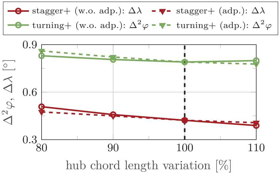
Angular deflections achieved at the blade tip for different hub chord length variations.
3.5.3. Impact of sweep and dihedral
Evaluating the parameter combinations that yield the highest achievable morphing for the respective scenarios (
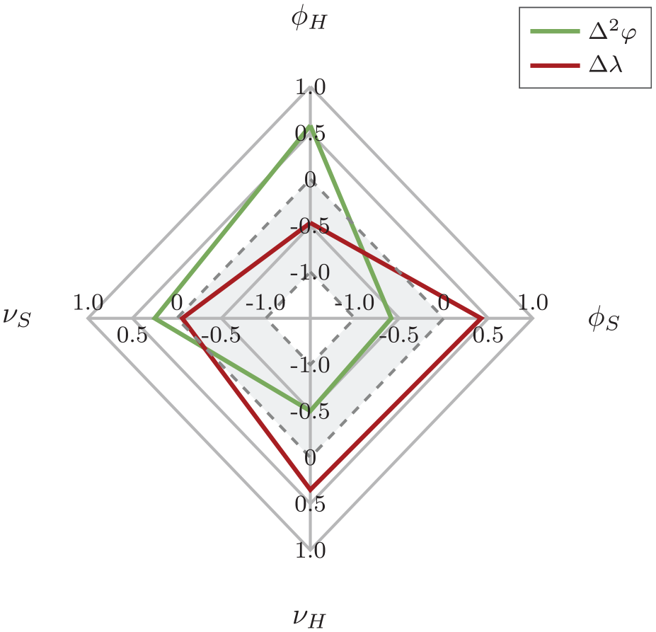
Correlation between 3D-design parameters and achievable angular deformations for the stagger+ actuation.
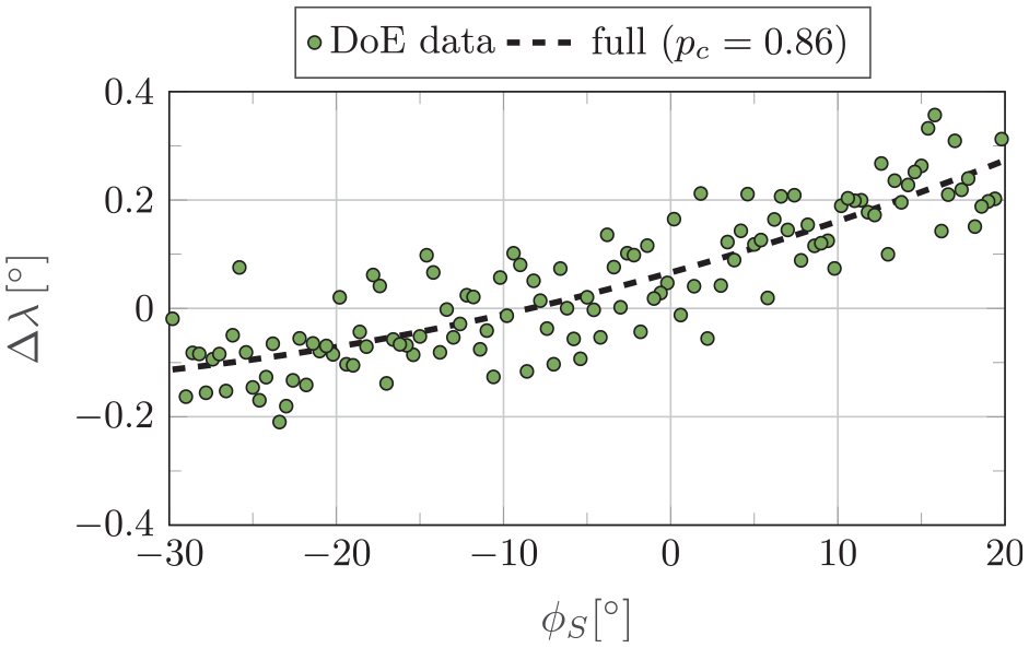
For the stagger+ actuation, all but shroud dihedral (
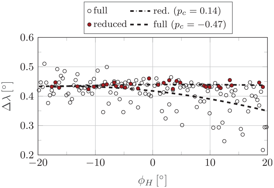
Regression between hub sweep angle
With the application of actuators that target the blade turning (turning+), 3D-design adaptions have no adverse effect on the angular morphing of blade turning and staggering (Figure 15).
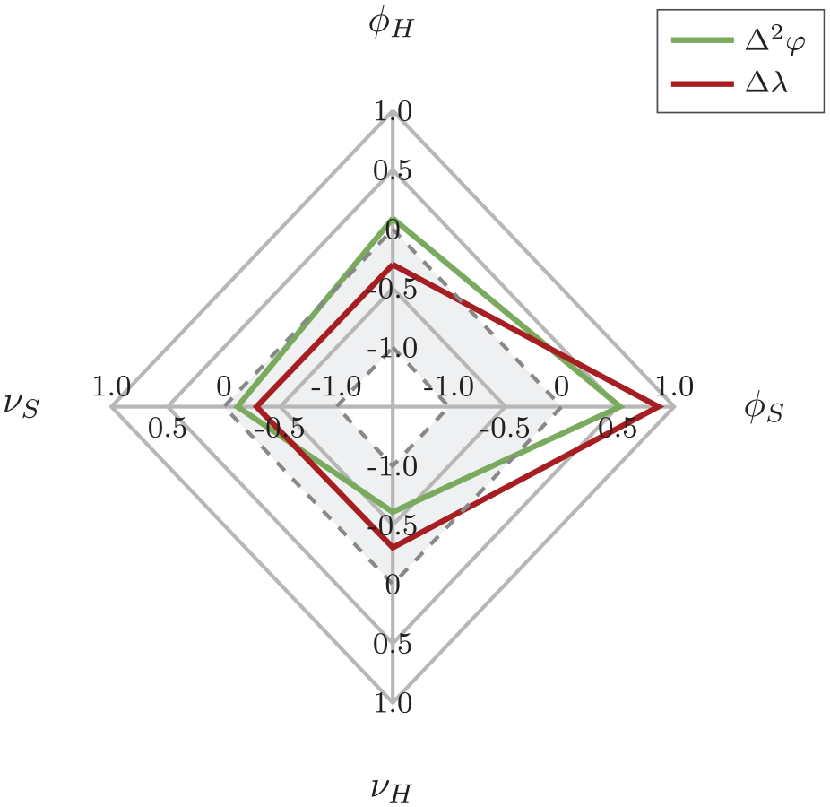
Correlation between 3D-design parameters and achievable angular deformations for a turning+ actuation.
As indicated by the configuration with the highest
Regression between shroud sweep angle
3.5.4. Impact of CFRP as blade material
Substituting titanium with CFRP as blade material yields the highest improvement potential within this investigation. According to Table 3,
Although the use of CFRP as a material shows significant advantages in terms of morphing performance, thermally induced phenomena must be considered for further maturation, which are not included in the basic analysis presented in the turbofan design section. The manufacturing of a CFRP blade specimen with integrated actuators requires curing temperatures between 80°C and 180°C due to the use of prepregs (Hexcel Corporation, 2025). Although these temperatures are below the Curie temperature of the piezoelectric lead zirconium titanate (PZT) fibers (360°C) applied in the actuators, PZT and the carbon fibers have significantly differing Coefficients of Thermal Expansion (CTE; Płaczek and Kokot, 2019). The piezoelectric PZT fibers of the actuators have a CTE of
4. Summary and conclusion
This research investigated the aerodynamic effects of boundary layer ingestion on an isolated blade passage and how the drawbacks induced can be mitigated by introducing a shape-morphing capability for the fan rotor.
4.1. BLI effects
The BLI induced inflow distortion shifts the speed lines to lower mass flow rates, while the overall peak efficiency of the stage is reduced. To uphold the required thrust of the engine, the fan rotor’s work input increases. This elevates blade loading and flow diffusion, especially in the tip region of the rotor. The part-load operating behavior of the fan is accelerated, which reduces the mass flow increment between the current operating point and the stability limit. Usually, the fan is designed for undistorted inflow conditions and the operating point defined by the engine’s working line. With flow distortion the inflow velocity is reduced and flow incidence causes the current operating point and the peak efficiency point to diverge. For a full anulus rotor this effect is less distinct, as the distortion pattern investigated is limited to the bottom area of the fan face. The aerodynamic drawbacks for the fan blades passing through the distorted flow regimes are however comparable (Giesecke and Friedrichs, 2019). An approach to align peak efficiency and current operating point is the reduction of the flow incidence in the distorted flow regimes of the rotor. With the goal to reduce flow incidence, two actuator configurations are introduced.
4.2. Shape adaption
The turning+ scenario achieves this correction by increasing the blade turning and therefore the leading edge camber angle
The stagger+ scenario evokes a speed line shift to lower mass flow rates, thereby increasing the surge margin of the current operating point. With the speed line shift, the mass flow and therefore the achievable total pressure ratio are reduced, which places all speed lines below the BLI reference. Part-load efficiency is slightly increased, which is most distinct for the 100% speed line. Compared to the turning+ scenario, the feasible angular morphing is however small and restricted to the upper 30% of the blade height. This limits the overall improvement potential of the stagger+ actuator configuration.
4.3. Fan re-design and morphing potential
In relation to the overall BLI effect on the fan performance, both scenarios only show a small improvement potential. A primary target of a shape-adaptive turbofan rotor is therefore the increase of the feasible deformations. Choosing a low hub-to-tip ratio fan design with a slender blade determines an overall higher blade thickness and bigger actuators. While the bigger actuators allow for higher actuation cantilevers, the higher blade thickness elevates the stiffness of the blade, counteracting its morphing capability. For the turning+ scenario, the thickness effect is dominant and further limits the morphing capability of the fan blade. The stagger+ scenario on the contrary benefits from the higher actuation cantilevers, which increases the maximum stagger angle morphing at the blade tip by 16%. Three-dimensional design adaptions have shown to further increase the rotor’s morphing potential for both actuation concepts. Here, the reduction of the blade hub profile length as a further 3D design measure has a moderate impact. The main effect that is introduced by sweep and dihedral is however not the achievable improvement of the primary morphing parameter, but an alteration of the morphing characteristic. Although the actuator configurations were optimized to affect only the blade turning or the blade twist, three-dimensionally shaping the blade extends the shape morphing to both parameters. For the stagger+ actuation, this effect is disadvantageous, as the increase in blade stagger angle morphing capability comes with a reduction of the blade turning. For the chosen operational scenario, both effects are contradictory, when measured against the expected reduction of the inflow incidence
4.4. Composite material
Most promising for the blade’s morphing behavior is the substitution of titanium through a tailored CFRP architecture. By designing the layers of the blade to account for the high rotational loads during operation, the deformability of the blade is increased. Especially, the turning morphing capability could be increased, but with the secondary effect of decreasing the blade staggering. As especially the increase in blade stagger angle has a positive impact on the surge margin, such a deformation is contradictory to the morphing goal within this investigation. Combining a CFRP blade with the stagger+ actuator configuration shows a higher benefit for the chosen scenario. Here a strong improvement of the stagger angle morphing is combined with a moderate increase in turning angle variation, allowing for an incidence correction of appr.
5. Outlook
Reducing the complexity of an asymmetric inflow distortion to the investigation of isolated blade passages is a strong simplification of the aerodynamic effects induced by the assumed distortion pattern. Although the chosen simulation approach has proven to be sufficient for the derivation of suitable actuator configurations, full annulus simulations are required to soundly quantify the achievable performance benefits of shape-adaptive fan rotor blading. The preliminary investigation of the interaction of the morphed rotor geometries with the distorted inflow has however shown that the expectable benefit is too small to fully compensate the BLI drawbacks. To accelerate the morphing benefit, different design measures were considered. With the goal of increasing the morphing capability of the fan rotor, an aerodynamically unconventional design was chosen. Especially, the slender rotor design and the chosen dihedral angles deviate from typical fan designs. Their effect on the local fan aerodynamics and the integral fan stage performance needs to be considered in future investigations. Also a combination of the design measures introduced is proposed to further improve the expectable aerodynamic effect. Here, the combination of fiber material structures with 3D-design measures is expected to be promising, as 3D-design adaptions have a significant impact on the deformability and load capacity of the blade. As the design of a shape-adaptive fan rotor blade is a compromise between maintaining structural integrity and providing a sufficient morphing capability, further structural integrity investigations need to conducted, also including the aerodynamic loads the blade experiences throughout a flight mission. The structural investigations proposed should also extend toward experimental investigations to validate the structural morphing methodology. To account for the impact centrifugal and aerodynamic loads have on the morphing behavior of a shape-adaptive fan rotor, stationary structural validation experiments with load equivalents are planned to provide valuable insights for a subsequent application of shape-adaptive turbofan blading in a rotating test rig environment.
Footnotes
Appendix
Declaration of conflicting interests
The authors declared no potential conflicts of interest with respect to the research, authorship, and/or publication of this article.
Funding
The authors disclosed receipt of the following financial support for the research, authorship, and/or publication of this article: We would like to acknowledge the funding by the Deutsche Forschungsgemeinschaft (DFG, German Research Foundation) under Germany’s Excellence Strategy – EXC 2163/1- Sustainable and Energy Efficient Aviation – Project-ID 390881007.
Data availability statement
The data that support the findings of this study are available from the corresponding author, upon reasonable request.