
Abstract
Composite materials/structures are advancing in product efficiency, cost-effectiveness and the development of superior specific properties. There are increasing demands in their applications to load-carrying structures in aerospace, wind turbines, transportation, medical equipment and so on. Thus, robust and reliable non-destructive testing of composites is essential to reduce safety concerns and maintenance costs. There have been various non-destructive testing methods built upon different principles for quality assurance during the whole lifecycle of a composite product. This article reviews the most established non-destructive testing techniques for detection and evaluation of defects/damage evolution in composites. These include acoustic emission, ultrasonic testing, infrared thermography, terahertz testing, shearography, digital image correlation, as well as X-ray and neutron imaging. For each non-destructive testing technique, we cover a brief historical background, principles, standard practices, equipment and facilities used for composite research. We also compare and discuss their benefits and limitations and further summarise their capabilities and applications to composite structures. Each non-destructive testing technique has its own potential and rarely achieves a full-scale diagnosis of structural integrity. Future development of non-destructive testing techniques for composites will be directed towards intelligent and automated inspection systems with high accuracy and efficient data processing capabilities.
Keywords
Introduction
Composite materials/structures are advancing in product efficiency, cost-effectiveness and the development of superior specific properties (strength and modulus). There are increasing demands in their applications to load-bearing structures in aerospace, wind turbines, transportation, medical equipment and so on. 1 Manufacturing of composite materials is a multivariable task, involving many procedures, where various types of defects may occur within a composite product, giving rise to significant safety concerns in service. 2 Detection and evaluation to maintain structural integrity are particularly challenging since composites are usually non-homogeneous and anisotropic. Defects and damage can occur within numerous locations at various levels of scale, making it difficult to track all the damage sites which can result in complex damage mechanisms. 3 In addition, damage accumulation within a composite is closely related to the actual strength, stiffness and lifetime prediction of the component. Therefore, robust and reliable non-destructive testing (NDT) of composites is essential for reducing safety concerns, as well as maintenance costs 4 to minimise possibilities for process disruption and downtime. These factors attract interest from both academic researchers and industrial engineers.
There are a wide variety of NDT techniques built upon different principles. These have demonstrated effectiveness in quality assurance throughout the whole lifecycle of composite products, that is, in process design and optimisation, process control, manufacture inspection, in-service detection and structural health monitoring. 5 There are reviews available on NDT methods used for composite research over different timelines, focusing on various aspects: for general methods and trends over last 30 years refer to,4,6–11 specific areas include those which concentrate on porosity in composite repairs, 12 crack damage detection, 13 bond defect determination in laminates, 14 thick-wall composites, 15 sandwich structures,16,17 large-scale composites, 18 smart structures, 19 as well as inspection and structural health monitoring of composites,20,21 especially for marine, 22 wind turbine23–26 and aerospace applications.27,28 Audiences are recommended to refer to further information on their specific interests.
This article reviews the most established NDT techniques for detection and evaluation to ensure the structural integrity of composite materials/structures; however, a full description of all methods is beyond the scope of this article. Instead, we aim to provide a practical review of the established and emerging NDT techniques and their applications to composite research. The American Society for Testing and Materials (ASTM) has developed more than 130 standards, guides and practices, containing technical specifications, criteria, requirements, procedures and practices for most of the NDT techniques. 29 We also include the standard practices for each NDT method available from the ASTM to provide guidance for researchers and engineers. These make it a unique state-of-the-art review article to cover the most up-to-date practical information for NDT techniques and their applications to composite materials and associated structures.
The article is organised as follows. Section ‘Defects and damage evolution in composites’ introduces the potential defects and damage evolution in composites. Section ‘NDT and evaluation techniques’ provides an overview of development and principles of NDT techniques and then elaborates on eight well-established NDT methods in subsections, covering a brief historic background, principles, standard practices, equipment and facilities for each NDT method in composite research. These include visual inspection (VI), acoustic emission (AE), ultrasonic testing (UT), infrared thermography (IRT), terahertz (THz) testing, shearography, digital image correlation (DIC), as well as X-ray and neutron imaging (NI) and these are described in sections ‘VI’, ‘AE’, ‘UT’, ‘IRT’, ‘THz’, ‘Shearography’, ‘DIC’, ‘XRI’ and ‘NI’, respectively. Section ‘Conclusion and outlook’ compares and discusses the benefits and limitations of above NDT techniques and further summarises their capabilities and applications to composite structures. This article is concluded by the further development of NDT techniques, which is driven by intelligent and automated inspection systems with high accuracy and efficiency in data processing.
Defects and damage evolution in composites
Manufacturing-induced flaws/defects can occur in many forms: unevenly distributed fibres cause resin-rich regions; laminate–tool interactions result in in-plane fibre waviness or out-of-plane fibre wrinkling;30,31 voids and porosities arise from poor resin infusion; inclusions from contaminated ambient conditions; misalignment of ply and fibre orientation; matrix cracking, laminate warping and buckling from build-up of thermal residual stresses during curing and so on.32,33 Flaws/defects act as stress concentration points, promoting crack propagation and delamination to reduce effective strength, stiffness and service time of composite products. 34 Although residual stresses can occasionally be beneficial, especially for producing morphing composite structures,35–38 they are usually detrimental. 32 A wide range of processes have been developed for the moulding of composite materials to reduce flaws, defects and build-up residual stresses that may occur during manufacture. These can involve multi-step processing, expensive consumables and equipment, to meet technical requirements. Typical industrial practice generally includes NDT inspection and evaluation of composite products to ensure their structural integrity and mechanical performance, which can be particularly challenging. 39
Figure 1 summarises the typical flaws and defects that may occur during manufacturing and the in-service damage evolution of a composite material/structure. There are no clear boundaries on the scales of different defects and damage (which also depend on composite constituents); thus, here we provide general guidance according to the published literature.

Manufacturing-induced flaws/defects, and in-service damage evolution of a composite material/structure, with their potential scale dimensions.
In-service damage evolution within a composite material/structure depends on composite constituents and loading conditions. Their failure processes are an accumulation of basic rupture mechanisms that include matrix cracking, fibre/matrix debonding, fibre fracture and pull-out, micro-buckling and waviness, delamination and so on.40,41 The damage process initiates at the nano- or micro-scale, where molecular chains, crystals and amorphous regions (for semi-crystalline thermoplastic polymers) or cross-linked molecular networks (for thermosetting polymers) carry loads until their limits are reached; damage then starts to accumulate on the micro-scale through crack propagation, interface debonding and micro-buckling, fibre fracture and pull-out, which lead to delamination, ultimately developing into macro-scale failure of the composite.
NDT and evaluation techniques
The term ‘NDT’ covers a wide range of analytical techniques to inspect, test or evaluate chemical/physical properties of a material, component or system without causing damage. Early established NDT techniques include ultrasonic, X-ray radiography, liquid penetrant testing (LPT), magnetic particle testing and eddy-current testing, which were initially developed for steel industry. Among these, ultrasonic and radiographic detection are also effective inspection techniques for composite structures. 17 It is difficult to select appropriate NDT techniques for a specific purpose; however, ASTM E2533 5 serves as a practical guide in using NDT methods on composite materials/structures for aerospace applications.
To date, there have been numerous NDT methods based on different principles, see Figure 2. They can be categorised into five groups: (1) VI (i.e. those visible to the human eye); (2) acoustic wave–based techniques, such as AE, nonlinear acoustics and ultrasonic waves; (3) optical techniques, which include IRT, THz testing, shearography, DIC; (4) imaging-based techniques, for example, X-ray/neutron radiography/tomography and micro-tomography; 4 (5) electromagnetic field–based techniques, such as eddy-current testing, remote field testing, magnetic particle inspection and magnetic flux leakage testing. 42

Categories of non-destructive testing and evaluation techniques.
Here, we focus on eight established and emerging NDT techniques and their applications to composite research in categories (1) to (4), with the exclusion of category (5). Since NDT methods in category (5) are based on electromagnetic induction, their applications are limited to conductive materials. 43 Eddy-current testing (ECT), for example, is well established and widely used for detecting cracks and corrosion in homogeneous metallic materials. Although it may be applicable to carbon composites, their conductivities are usually very low and inhomogeneous due to the layup and bundling of the conductive fibres. 44 This leads to further issues and difficulties for ECT to be an efficient and cost-effective solution for most composite NDT applications.
The measurement principles of each elaborated NDT technique depend on the characteristics of the electromagnetic waves based. Figure 3 shows the electromagnetic spectrum with divided wavelength sub-regions: the soft boundaries indicate terminologies for the subsections. Developments in generation and detection within each spectral regime have induced numerous industrial applications. 45 Ionising radiation consists of short-wave ultraviolet (UV), X-rays, gamma-rays or highly energetic particles, such as α-particles, β-particles or neutrons, which are harmful to biological tissues, whereas the remaining part of the spectrum is considered to be non-ionising radiation.
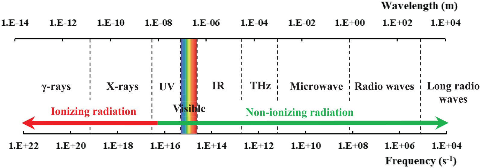
Diagram of the electromagnetic spectrum, defining the various regions of radiation according to their range of frequencies and wavelengths.
To date, there have been a growing number of research activities in this field. We performed an electronic database search on articles published in last 30 years (until 31 December 2019) using the Web of Science Core Collection database, to trace the trends in using various NDT techniques within composite research, see Figure 4. The use of AE on composites has a long history and is well established; it is still active in a relatively steady state. Due to significant developments in equipment manufacture, computing power, imaging processing and acquisition techniques over last three decades, there have been rapid increases in the application of IRT, ultrasonic, DIC and X-ray imaging (XRI) to non-destructive detection and evaluation of composite materials/structures. THz-based NDT technology has become a promising technique for composite inspection within the last decade.46,47 Research articles on the shearography technique are less, but it was promoted significantly by the invention of the laser in the 1960s; 48 thus, it is well-established and widely used for industrial NDT, especially in aerospace.49,50 Although NI shares similar principles to XRI, the generation of neutrons is more expensive than for X-rays, the former requiring either a nuclear reactor or spallation process. 51 This has resulted in relatively few publications on its application to composite materials.

A comparison of publication numbers on various NDT methods and their applications to composite materials/structures in the last 30 years; data are retrieved from Web of Science Core Collection database.
VI
VI is the most basic type of NDT technique to inspect damage. It is quick, economically viable and flexible, while its disadvantages are quite obvious and significant. 11 VI methods include visual and optical testing (VOT) and LPT. VOT analysis is a leading procedure in the monitoring of surface imperfections for acceptance–rejection criteria during composite parts production. 52 The LPT technique is a widely applied, low-cost inspection method. It has been used in non-porous materials to detect casting, forging and welding surface defects including cracks, surface porosity, leaks in new products, in-service fatigue cracks and so on.
VI methods are particularly effective in detecting macroscopic flaws, such as poor joints, erroneous dimensions, poor surface finish and poor fits. It usually employs easy-to-handle equipment such as miniature cameras or endoscopes. 23 VI studies of small integrated circuits have shown that the modal duration of eye fixation from trained inspectors was ∼200 ms. Here, variation by a factor of six in inspection speed led to a variation of less than a factor of 2 in inspection accuracy; inspection accuracy also depends on training, inspection procedures and apparatus (optics, lighting, etc.). 53
AE
Damage occurrences within a composite produce localised transient changes in stored elastic energy; the energy releases stress waves, resulting in fibre breakage, matrix cracking, debonding, delamination and so on. 3 AE-based NDT techniques detect and track these sudden releases of stress waves through arrays of highly sensitive sensors or transducers, 54 as illustrated in Figure 5. Use of the AE method started in the early 1950s when Kaiser 55 first used electronic instrumentation to detect audible sounds produced by tensile deformation of a metallic specimen. His discovery on the effect of sample stress history on the production of AE became known as the ‘Kaiser effect’. 56 AE was first applied to the study of composite materials in the 1970s, 3 and it has now been widely used in various aspects of composite research. 57

Schematic of localised transient changes in stored elastic energy within a material system under loading, showing the measuring principle of the acoustic emission-based NDT technique.
The AE method is unique in that (1) the signals, i.e. stress waves, are emitted by the testing sample, not from external sources (as with other NDT methods); (2) strain or displacement data are usually recorded, rather than as geometrical defects; (3) it monitors dynamic processes in a material, tracking the development of certain defects, which significantly benefits fatigue tests. It has been reported that AE-based NDT can detect fatigue cracks, fibre fractures, matrix micro-cracks, interface debonding as well as delamination. 11 However, there are also certain difficulties. Data collected during the loading of a composite system can be in different forms; the most common is the AE amplitude signal. Processing and analysis of data are time-consuming and require certain skills and experience: 3 in particular, the distribution of amplitudes exhibits overlapped areas, which sometimes causes difficulties in associating these with the damage mechanisms.
Efforts have been made to address these issues. A common approach is to analyse multiple parameters to complement the damage analysis, such as cumulated event counts,58,59 energy, 60 duration 61 or frequency of the received amplitude signals. 62 Other solutions include verifying damage modes through other methods, for example, microscopy, to provide more reliable analysis. 63 Standardised practices of using AE include ASTM E1067 64 on examining glass fibre–reinforced plastic (GFRP) tanks/vessels; ASTM E1118 65 on composite pipes; ASTM E2191 66 on filament-wound composite pressure vessels; ASTM E2076 67 on composite fan blades as well as ASTM E2661 68 on plate-like and flat composite structures for aerospace. Table 1 summarises some of the commercial suppliers of AE-based NDT systems, which may be applied to composite research.
Summary of suppliers of devices and systems used for the acoustic emission-based NDT technique.

NDT: non-destructive testing.
Please note the information in this table is incomplete, and not for advertising purposes – it should not be taken as endorsements by the authors.
There is also some interest in a combined method of AE and UT, namely the acousto-ultrasonic technique (AUT), as first introduced by Vary 75 in 1981. By adopting the ultrasonic transducer, repeated ultrasonic pulses are introduced into a material, and resultant waveforms carry the morphological information that contributes to damage mechanisms. A concept of ‘stress wave factor’ is defined as a relative measurement of efficiency of energy dissipation to indicate regions of damage. 76 In NDT, the AUT is mainly used to determine the severity of internal imperfections and inhomogeneities in composite materials. 11
UT
UT is an acoustic inspection technique, which is expanding rapidly into many areas of manufacturing and in-service detection. 77 It operates through surface wave testing, bulk wave propagation and guided wave propagation, while the guided wave analysis technique is superior for anisotropic materials. 78 For further information, the use of ultrasonic bulk wave testing in the sizing of flaws has been reviewed by Felice and Fan. 79 For NDT inspection of composite materials, elastic waves or ‘Lamb waves’ propagate in selective directions due to their anisotropic nature which makes the technique effective. UT operates in three detection modes, that is, reflection, transmission and backscattering of pulsed elastic waves in a material system. 17 It introduces guided high-frequency sound waves (ranging from 1 kHz to 30 MHz 4 ) to effectively detect flaw size, crack location, delamination location, 80 fibre waviness, 31 meso-scale ply fibre orientation 81 and layup stacking sequence. 82
There are various types of UT systems with hundreds of guided wave modes and frequencies being available. 78 A typical UT system consists of a transmitter and receiver circuit, transducer tool and display devices, see Figure 6. The transmitter can either be arranged at an angle to the sample or in the form of phased array. 83 The guided Lamb waves can be generated using (1) ultrasonic probe, (2) laser, (3) piezoelectric element, (4) interdigital transducer or (5) optical fibre. 84 Table 2 provides some suppliers of UT equipment which may be applied to composites research.

Principle of ultrasonic testing a composite material in transmission mode.
Summary of suppliers for the ultrasonic-based NDT technique.

NDT: non-destructive testing.
Please note the information in this table is incomplete, and not for advertising purposes – it should not be taken as endorsements by the authors.
The potential types of damage that guided Lamb wave-based NDT can provide are summarised by Rose; 77 the mode selection, generation and collection, modelling and simulation, signal processing and interpretation have been well documented by Su et al. 84 A later review on guided waves for damage identification in pipeline structures is provided by Guan et al. 91 UT techniques for composites have been standardised: ASTM E2373 92 gives the requirements for developing a time-of-flight (TOF) UT examination; ASTM E2580 93 for inspections on flat composite panels and sandwich structures in aerospace applications; ASTM E2981 94 for filament-wound pressure vessels in aerospace applications.
IRT
IRT is a method used to detect and process infrared energy emissions from an object by measuring and mapping thermal distributions. 95 Infrared energy is electromagnetic radiation with wavelengths longer than visible light, see Figure 3. The discovery of thermal radiation dated back to the early 1800s. 52 Every object with a temperature higher than absolute zero emits electromagnetic radiation that falls into the infrared spectrum. 96 IRT has undergone rapid development in the last 30 years with developments in infrared cameras, data acquisition and processing techniques. It provides capabilities in terms of non-contact, non-invasive, real-time measurement, high resolution and covering large volumes. 97
The IRT method is effectively used to monitor the entire life of a product, from manufacturing (on-line process control), to the finished product (NDT evaluation) and to in-service maintenance and diagnostics. 52 It has been applied to research and various aspects within the industry, including NDT, 98 building diagnostics, 99 adhesion science, 52 condition monitoring, 100 predictive or preventive maintenance, 101 medical diagnostics, 102 veterinary medicine 103 and many more. As for composite materials and structures, IRT-based NDT has also been widely used, especially during manufacturing for aerospace applications. It is used to detect inclusions, debonding, delamination and cracked networks. 27 Both Boeing and Airbus have used IRT for structural health monitoring to ensure the integrity of their composite products. 97
A typical IRT system contains an infrared radiometer, with/without energy source, synchronising and control panel, display software, see Figure 7. The radiometer is the core of the IRT system; it absorbs IR energy emissions and converts them into electrical voltage or current signals. They are then transmitted and displayed as infrared images of temperature distribution. 52 The use of IRT can be implemented through (1) passive and (2) active thermography (AT). 104 In passive thermography (PT), thermal radiation is directly emitted from surfaces of the test body under natural conditions and subsequently monitored. For AT, a heating or cooling flow is generated and propagated into the test object, and thermal responses according to the Stefan–Boltzmann law are then detected and recorded to reveal internal structures. Recent advances in signal processing techniques and equipment developments have made the AT method more practical and effective than the conventional PT approach.105,106 Table 3 gives some suppliers of IRT equipment which may be applied to composites research.

Schematic of the measurement principles for an infrared thermography system in reflection mode.
Summary of commercial infrared thermography systems and their key parameters applied to composite research.

Please note the information in this table is incomplete, and not for advertising purposes – it should not be taken as endorsements by the authors.
Based on energy stimulation methods, the AT method has developed into different categories. First, optical thermography is the most traditional form of IRT, using optical sources such as photographic flashes, halogen lamps or lasers, which are also known as pulsed thermography, 117 modulated (lock-in) thermography 118 or laser thermography,119,120 respectively. Second, induction thermography, which shares similar principles to ECT, that uses electronic or magnetic currents to induce energy waves.121–124 Third, mechanical thermography, which uses mechanical waves to interact with internal structures to detect thermal waves from defects; 125 it can be implemented through vibrothermography,126,127 microwave thermography128,129 or ultrasonic lock-in thermography 130 which attracts increasing interest. Yang and He 131 have presented a comprehensive review of the optical and non-optical IRT methods and their NDT applications in composite materials/structures. The reader is referred to ASTM E2582 132 for standard practice on using IRT with composite panels and repair patches in aerospace applications.
THz testing
THz waves lie within the electromagnetic spectrum from 100 GHz to 30 THz, 133 which belong to non-ionising radiation and are not harmful to biological tissues (Figure 3). There are many THz wave sources in nature, although previously it has been difficult to generate and detect THz waves, so for many years, there have been few applications. 134 Due to breakthroughs in ultrafast lasers and ultra-micro machining technologies during the 1980s,135,136 there has been a rapid expansion in applications for THz science and technology. 46 THz-based NDT technology has also started to be a promising technique for composite inspections,2,47 offering advantages in terms of higher resolution and better penetration in most materials compared to other techniques. 137
THz waves have good penetrating power for non-metallic, non-polar materials, including foams, ceramics, glass, resin, paint, rubber and composites. THz-based NDT techniques use the wave characteristics to detect, analyse and evaluate material systems, which has attracted wide interest in various fields, leading to rapid expansion. 138 Figure 8 shows an example of a typical setup of the THz-based NDT method, presenting the basic measuring principles in transmission mode. 45 The system induces THz short waves into a material, which interact with different phases, inclusions, defects or damage. Internal structures within the material are determined by detection and analysis of reflected or transmitted THz waves. Therefore, the multi-phase and multi-layered nature of composites are well-suited to THz-based NDT – it offers multi-scale, more comprehensive information to detect and reveal internal structures and damage within a composite. 47
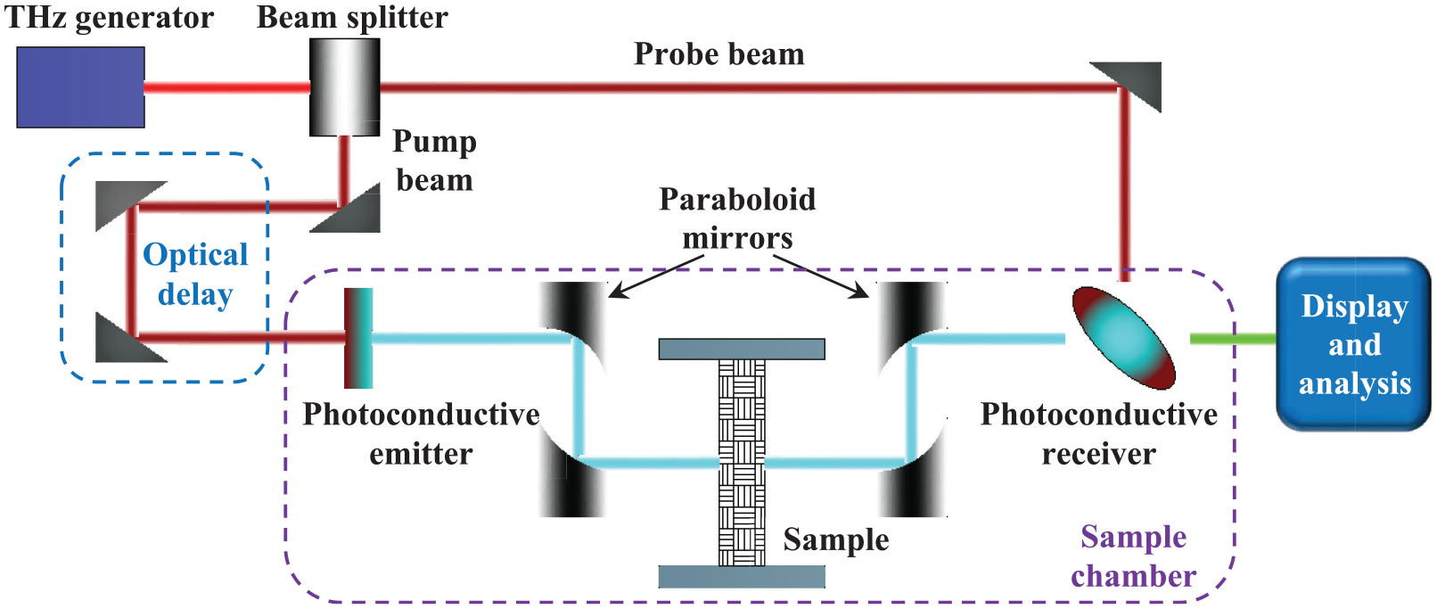
Schematic showing the measurement principles of THz time-domain spectroscopy using photoconductive antennas.
The THz-based NDT technique is usually implemented through (1) a THz time-domain spectroscopy system (THz-TDS), also known as pulsed spectroscopy, or (2) a continuous wave (THz-CW) system. The detection setup determines how information is evaluated within composite materials. In the THz-TDS system, short-pulsed THz waves are generated by optical excitation of a photoconductive antenna using a laser pulse emitting in the femtosecond regime, 133 the time-dependent evolution of the THz electric field of a single pulse is measured, which can be used to determine phase information within a composite. For the THZ-CW system, high-power THz waves are produced through gas lasers, quantum cascade lasers or parametric sources 2 and phase information is measured by recording the average intensity (related to the amplitude of the wave) of the electromagnetic field. Table 4 shows some of the commercialised THz-based NDT systems and their key parameters. As an emerging NDT technique, standardised practice on using the THz approach is still developing.
Summary of terahertz-based NDT system suppliers.
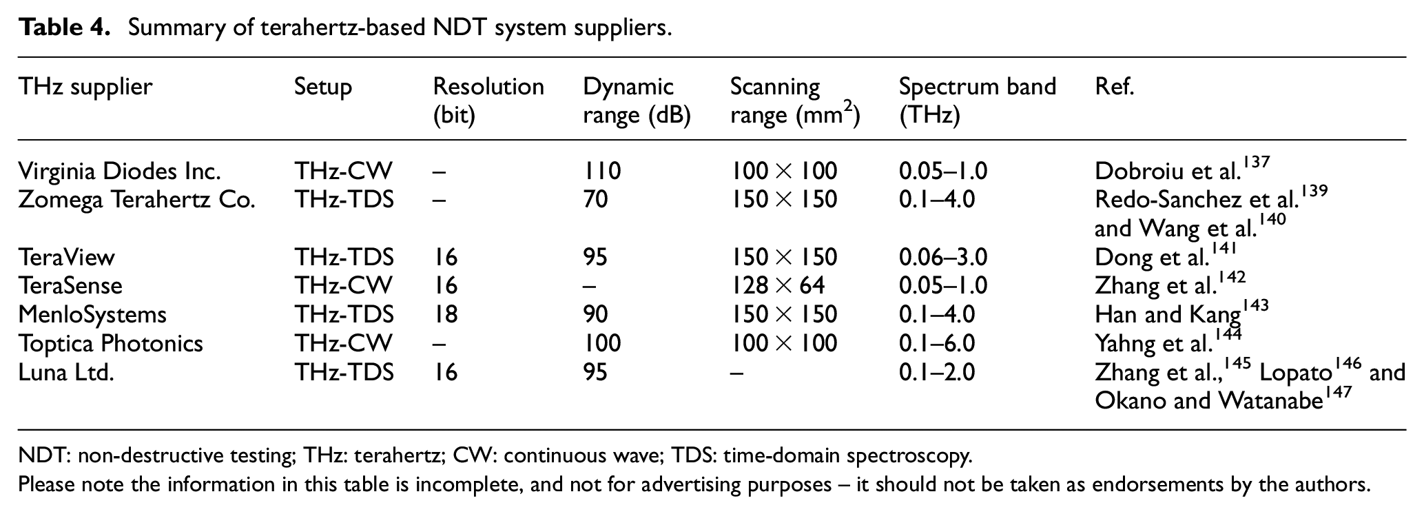
NDT: non-destructive testing; THz: terahertz; CW: continuous wave; TDS: time-domain spectroscopy.
Please note the information in this table is incomplete, and not for advertising purposes – it should not be taken as endorsements by the authors.
There have been several reviews regarding applications of the THz-based technique, focusing on different aspects: Dhillon et al. 46 presented a comprehensive review on the roadmap of THz science and technology; Jansen et al. 148 reviewed progress and applications of THz systems in the polymer industry; Amenabar et al. 2 summarised the detection and imaging methods using THz waves, as well as their applications in composites; Zhong 47 further summed up the most recent advances.
Shearography
Shearography testing (ST) is a laser-based non-contact NDT technique, using a full-field speckle shearing interferometric method to overcome the limitations of holography testing. 49 This technique was first described and applied by Leendertz 149 and Leendertz and Butters 150 in the 1970s. To date, it has been used in various fields as a practical quantitative inspection tool to detect flaws and defects,151–153 leakage, 154 delamination and damage,155,156 as well as measurement of displacement and strain,157,158 curvature,159–162 residual stress,163–165 mechanical analysis,166,167 surface profiling 168 and dynamic vibration.169–171
A typical shearography setup is shown in Figure 9. A laser beam illuminates a sample surface, and the beam is then scattered and reflected. The resulting speckle pattern is imaged through a shearing device (Michelson interferometer or diffractive optical element), which divides it into two coherent images with one being monitored during deformation. A controlled stressing process is essential and is applied through thermal,172,173 vacuum,163,174 vibration, 153 microwave 175 or mechanical loading. 176 The interferometric pattern is then captured and recorded by a charge-coupled device (CCD) camera, which results in a fringe pattern that contains structural information. 177 It has been adopted for inspection and evaluation in various composite products, for example, pipes,178,179 sandwich structures,16,17,180 wind turbine blades, 181 aerospace structures,182–184 as well as racing tyres. 185 An example of standard practice using shearography for polymer composites and sandwich core materials in aerospace is represented by ASTM E2581. 180 Some suppliers of commercialised shearography systems are given in Table 5.

Schematic illustration of a shearography system.
Summary of commercialised shearography system suppliers, and their key parameters applied to composite research.

Please note the information in this table is incomplete, and not for advertising purposes – it should not be taken as endorsements by the authors.
DIC
DIC is a simple and cost-effective optical NDT technique for measuring strain and displacement, which are critical parameters within engineering and construction projects. It was developed in the 1980s 193 and has become widely used only in recent years due to the rapid development of computers and image acquisition methods. Images are usually captured through CCD cameras, possibly with the aid of microscopy. The DIC system tracks blocks of random pixels on a sample surface and compares digital photographs at different stages of deformation to build up full-field two-dimensional (2D) or three-dimensional (3D) deformation vector fields and strain maps. 194 Thus, any changes in the structure or surface can easily be reflected to give details on surface strain, deformation or crack propagation, making it ideal for studies of crack propagation and deformation. It offers more accurate strain monitoring than conventional extensometers or strain gauges, which often suffer from imperfect attachment to the measured surface and the limitations imposed by values that are averaged over the gauge length. 195
Figure 10 shows a typical DIC system for strain mapping of a composite sample; here, special illumination may be required. The sample is sprayed with a white stochastic speckle pattern prior to testing and two CCD cameras need to be calibrated each time. Imaging data can be analysed through commercialised software to reveal changes in speckle with reference images and strain or deformation can be calculated during the tests. Thus, quality of the speckle pattern is vital for accuracy and precision in the DIC technique. 196 Pan 197 presented the historic developments, recent advances and future of DIC for surface deformation measurement; Hild et al. 198 discussed the capabilities of DIC in damage measurements; Aparna et al. 199 summarised studies on fatigue testing of composites using the DIC technique. Therefore, they are not elaborated here. Table 6 summarises some suppliers of DIC systems and certain examples in the literature. Audiences are recommended to refer to each supplier for full details.

Schematic of a typical stereo-DIC setup for strain mapping of a composite sample sprayed with stochastic speckle pattern.
Summary of suppliers of DIC systems and their key parameters applied to composite research.
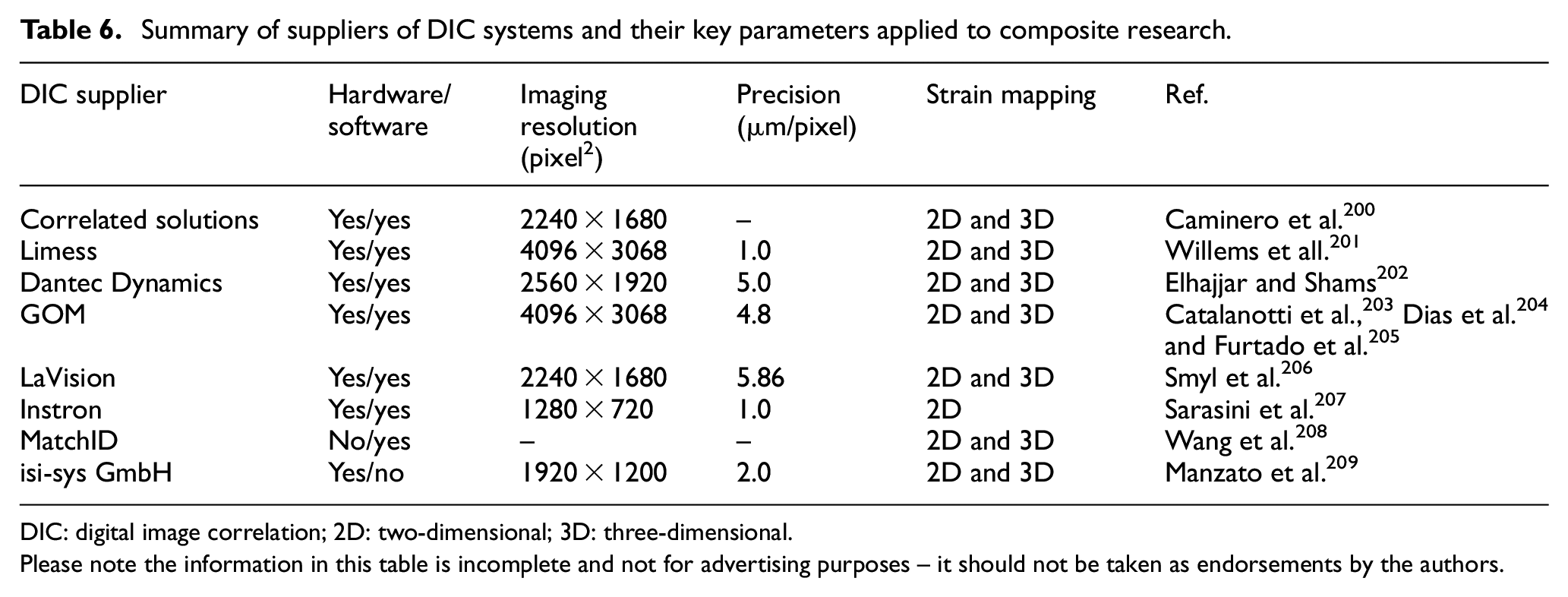
DIC: digital image correlation; 2D: two-dimensional; 3D: three-dimensional.
Please note the information in this table is incomplete and not for advertising purposes – it should not be taken as endorsements by the authors.
Given the flexibility and versatility of DIC systems, standardisation of the DIC technique is difficult or even impossible to be applicable to each individual situation. 197
Imaging techniques
Imaging techniques refer to the NDT methods that are based on phase-contrast imaging, which were first developed in the 1930s. 210 They enable high-resolution imaging (a few angstroms), making it possible to distinguish features at atomic or molecular levels. Developments in digital imaging technology and synchrotron radiation facilities have promoted the use of imaging techniques since the 1990s. 211 To date, it has been reported that XRI is carried out either through lab-based X-ray tubes or synchrotron light sources; alternatively, NI uses neutrons generated from fission reactors or spallation sources. 212 Both X-ray and neutron radiography have developed to be indispensable tools in various research fields ranging from solid matter to soft tissues. 211
Synchrotron X-ray and neutron radiation are NDT techniques that provide insights into micro-structures, residual stress, strain and stress fields, crystallographic textures and so on, at atomic and crystalline levels. Their measurement and detection principles are similar, mainly depending on scattering techniques, see Figure 11. The incident light beams (monochromatic or white) are directed onto a sample, the scattered beams are captured by the detectors as a function of momentum transfer and/or transferred energy ΔE. 213 Diffraction patterns from a material in (a) can be used to characterise the crystalline structure, residual stress and crystallographic textures; in (b), small-angle scattering (SAS) uses smaller scattering angles than (a) to investigate material structures with various substances to provide quantitative statistical information at nanoscale levels; in (c), reflectometry is used to study the surface morphology of thin films or multi-layered composites and so on; 214 in (d), spectroscopy is performed to determine electronic, vibrational or magnetic excitations and diffusional processes in solids and liquids.

Schematic of synchrotron and neutron measurement techniques: (a) diffraction, (b) small-angle scattering, (c) reflectometry and (d) spectroscopy.
Although synchrotron and NI share basic principles, the neutron technique is superior in terms of penetration depth; that is X-rays (photons) can only be used non-destructively for examination in the near-surface regions. 215 Neutrons carry no electric charge, so there is no electrostatic interaction with the electron cloud of an atom. 213 The characterisation and analysis of residual stresses in materials science using synchrotron and neutron radiation has been documented by Fitzpatrick and Lodini, 213 and Hutchings et al. 216 Also Banhart et al. 212 have reviewed the applications of X-ray and NI to materials science and engineering.
XRI
A commonly used laboratory-based X-ray source for imaging is the X-ray tube, as schematically illustrated in Figure 12. A bias voltage of 30–60 kV is applied between the filament and metallic target in an evacuated X-ray tube, causing electrons emitted from the filament to collide with the metallic target at high velocity (energy) and radiate X-rays. The wavelengths of the X-rays are about 0.5–2.5 Å and depend on the target material. The most commonly used metallic target is copper, which emits strong X-rays with a wavelength of 1.54 Å. 217 Laboratory XRI systems are usually cheaper and easier to access and are suitable for materials with higher phase contrast, such as glass fibre–reinforced composites. The acquisition time for laboratory XRI ranges from minutes at low resolution (sub-millimetre) to hours or even days at high resolution (sub-micron). 218
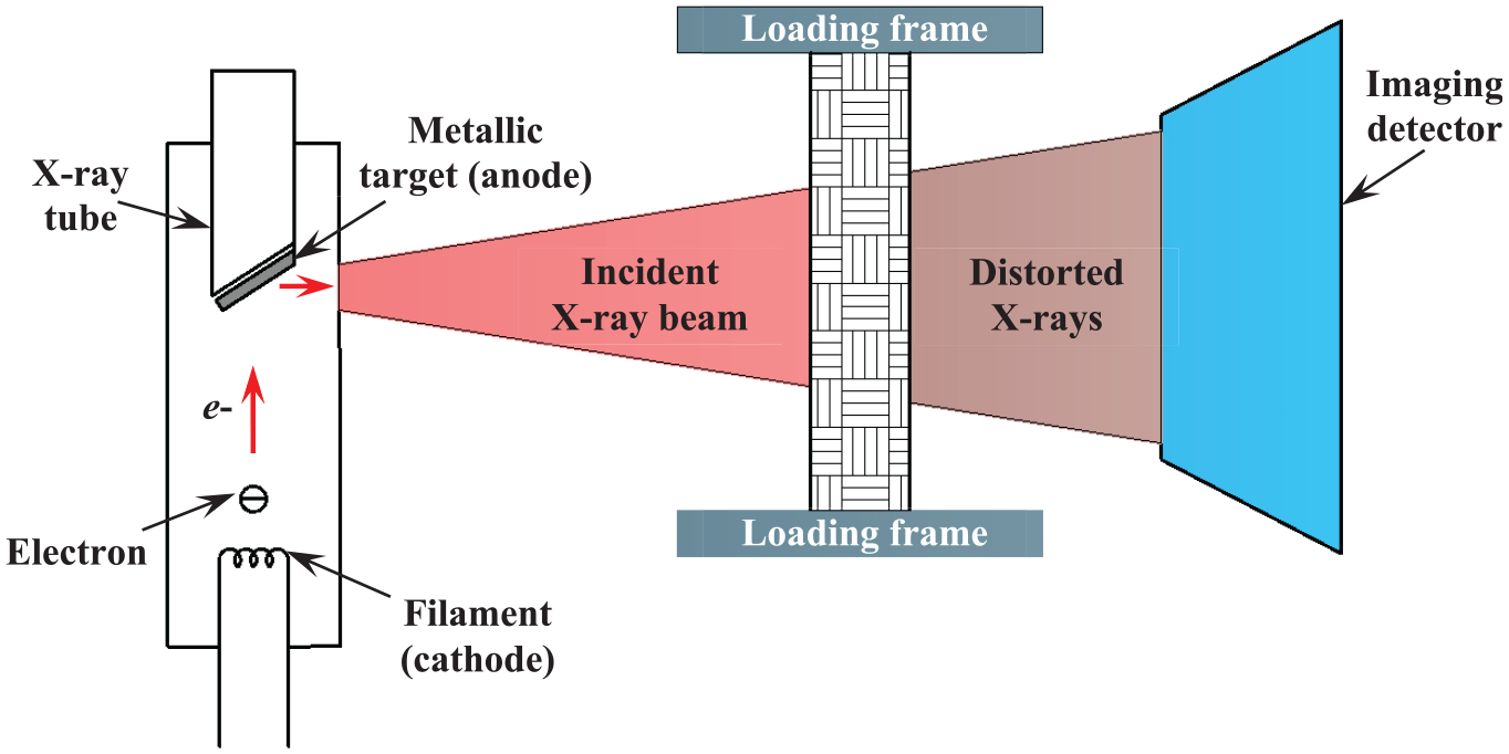
Schematic representation of laboratory-based X-ray imaging.
A major disadvantage of laboratory XRI systems is the lack of capability to penetrate deeply into engineering materials, which depends on X-ray energy and wavelength. 216 Although gamma-rays have higher penetrating capacity than X-rays, they are usually generated from a radioactive source, which cannot be turned off and is difficult to adopt as a compact source to provide a photon flux comparable to an X-ray tube; thus, detection efficiency is fairly low and long measuring times are required. 219
The limitations on penetration depth have been overcome by the rapid development of synchrotron facilities. Laboratory X-ray sources produce polychromatic and divergent X-ray beams, while a synchrotron X-ray beam is parallel, monochromatic, more coherent, with higher orders of flux and brightness. These factors determine the image quality and acquisition time. A synchrotron XRI system offers much higher levels of both signal-to-noise ratio and phase contrast, which makes it superior for low contrast materials, such as carbon fibre–reinforced composites. The high flux and brilliance of the X-ray beam allow very fast imaging acquisition with high resolution; for example, 1 tomogram per second with 1.1 μm spatial resolution using the TOMCAT beamline at the Swiss Light Source facility. 220
Synchrotron facilities have gone through four generations of technical evolution. The first-generation synchrotron facility was built in the United States in 1946 and was primarily used for high-energy particle physics. The second-generation synchrotrons were dedicated to the production of synchrotron light in the 1980s, which used bending magnets to generate synchrotron light. The third-generation light sources originated in the 1990s, 221 with facilities that used insertion devices (wigglers and undulators) to produce intense and tuneable X-ray beams. The fourth-generation facilities will be based on free electron lasers which offer more advanced capabilities to generate brighter light sources. 222 Currently, there are about 50 synchrotron facilities around the world, supporting various investigations in engineering, health and medicine, materials science, chemistry, cultural heritage, environmental science and many more.222–231 Table 7 summarises the third- and fourth-generation synchrotron light source facilities throughout the world. Given that the first third-generation synchrotron facilities were built in 1993, some will be subjected to upgrading in the near future. 231
Summary of third- and fourth-generation synchrotron light sources in operation and under construction worldwide.

Brilliance (brightness) is shown in photons/s/mrad2/mm2/0.1%bw.
XRI can also be implemented through different methods as recently presented by Liu et al.; 210 Garcea et al. 218 reviewed the applications of X-ray computed tomography (CT) to polymer composites. Standard practice in using computed radiography (X-rays or γ-rays) for metallic and non-metallic materials is recommended in ASTM E2033; 232 ASTM E2662 233 provides guidance on the radiographic examination of flat composite panels and sandwich core materials for aerospace applications.
NI
The neutron was discovered by Sir J Chadwick 234 at Cambridge in 1932 through the collision of beryllium by α-particles from polonium. Neutrons have a wave character, their wavelengths are in the order of interatomic distances (∼0.1 nm) and kinetic energies close to atomic vibration energies (∼10−2 eV). Thus, they give rise to the possibilities of diffraction and inelastic scattering studies, which were experimentally demonstrated in 1946 by Wollan and Clifford using the Graphite Reactor at Oak Ridge National Laboratory, in the era of the Manhattan Project in the United States. 213 Important progress was made on neutron strain scanning (NSS) during the 1960s and 1970s. Techniques such as small-angle neutron scattering (SANS), neutron TOF scattering, backscattering or spin-echo techniques and neutron reflectivity subsequently broadened the applications of NSS to larger scientific domains such as solid-state chemistry, liquids, soft matter, materials science, geosciences and biology. 235
A schematic example of NSS using ENGIN-X (ISIS Neutron and Muon Source, Rutherford Appleton Laboratory, UK) is presented in Figure 13. 236 The pulsed neutron beam with a wide range of energy travels to the sample and, being scattered, the detectors then collect the diffracted neutrons at a fixed angle of 2θb. As neutrons can penetrate deeply into composite materials, strain/stress can be non-destructively measured. 237 Neutrons are difficult and expensive to produce – neutron sources are usually generated through either nuclear fission reactors (continuous neutron sources) or neutron spallation (pulsed neutron sources). Neutron source facilities are summarised chronologically in Table 8.213,238,239
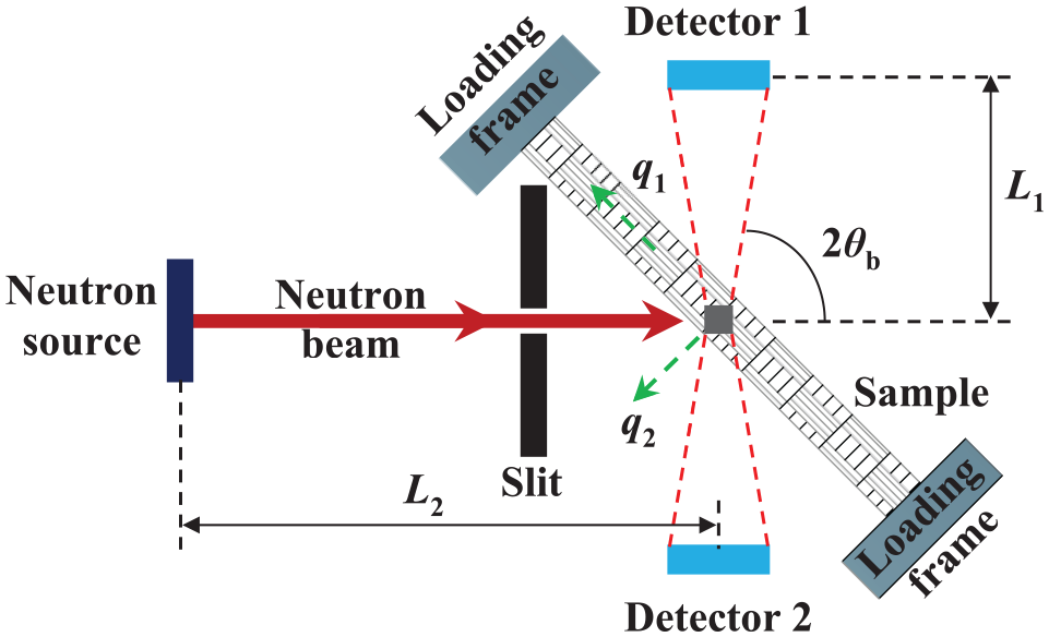
Schematic representation of a time-of-flight neutron strain scanner at the ENGIN-X. The elastic strain is measured along with the directions of the impulse exchange vectors, q1 and q2, through the two detectors.
Summary of neutron source facilities worldwide and their basic parameters.

NI has progressed as a reliable NDT technique, in the forms of neutron topography and radiography; specialised instrumentation at pulsed neutron sources includes RADEN@J-PARC 240 and IMAT@ISIS. 241 Neutron tomography allows 2D or 3D imaging of the attenuation coefficient distribution within a material system; thus, internal structures and material composition can be visualised; 242 neutron radiography is a transmission imaging technique for heterogeneous materials, taking advantage of the scattering and/or absorption contrast between different elements. 243
NI offers a typical spatial resolution of a few hundred microns 244 and below 10 μm in the best case. 245 Although XRI is able to provide sub-micron resolution, NI offers better sensitivity to light elements, especially hydrogen. 245 In terms of efficiency, NI may take several hours (days) compared to minutes or even seconds for XRI; this is due to the low neutron flux, dependency on the number of slices/rotation steps and the materials under investigation. The fundamentals, instrumentation and early applications of NI are covered by Strobl et al.; 246 for recent advances and applications, refer to Kardjilov et al. 247 and Woracek et al. 245
Conclusions and outlook
NDT techniques are invaluable as tools for testing and evaluation, as may be required during various stages within the lifetime of a composite product. It is clear that each technique has its own potential but rarely achieves the capabilities for a full-scale diagnosis of possible defects and damage evolution in a composite system. Table 9 presents the benefits and limitations of the reviewed NDT methods. Appropriate selection of a suitable NDT technique can be challenging but is clearly essential to provide appropriate information for maintaining the structural integrity of composite materials and structures.
Benefits and limitations of established non-destructive testing techniques used in composite research.

NDT: non-destructive testing; VI: visual inspection; AE: acoustic emission; UT: ultrasonic testing; IRT: infrared thermography; THz: terahertz; ST: shearography testing; DIC: digital image correlation; XRI: X-ray imaging; NI: neutron imaging; 2D: two-dimensional; 3D: three-dimensional.
The applications and capabilities of each reviewed NDT technique for detection and evaluation of defects and damage evolution in composite materials/structures are summarised in Table 10. As the volume and structural complexity of composite parts continue to grow, the uses of multi-NDT techniques are becoming increasingly popular in maintaining structural integrity; research in this approach is also growing rapidly.
Applications and capabilities of established NDT techniques for composite inspection and evaluation.

NDT: non-destructive testing; AE: acoustic emission; UT: ultrasonic testing; IRT: infrared thermography; THz: terahertz; ST: shearography testing; DIC: digital image correlation; XRI: X-ray imaging; NI: neutron imaging.
The initial development and application of various NDT techniques are driven by demands from aerospace industries, which rapidly expand to other fields. AE, ultrasound, IRT, shearography, DIC and XRI represent the main techniques within composite industries and continue to play essential roles especially in aerospace, automotive, marine and construction applications. NDT techniques based on ultrasound, IRT and DIC are versatile and cost-effective solutions, which have been used extensively in many industrial fields, as well as academic research tools. THz waves can pass through opaque materials and detect internal defects and damage; thus, it is a promising NDT technique, possessing great potential in the near future. Innovation and development of compact and portable NDT devices will continue to have a major role for future NDT equipment as these will offer in-service or in-situ inspections to facilitate the decision-making process.
Considering the complex nature of defects and damage detection in composites, the future development of NDT techniques will increasingly depend on intelligent and automated inspection systems with high accuracy and efficiency in data processing. Machine learning and deep learning provide significant potential for the NDT evaluation of composite materials – artificial intelligence–based approaches offer fast decision-making without human interference. Various automated diagnostic systems have been proposed for different NDT techniques to offer fast and accurate analysis. These are achieved through artificial neural network coding or algorithms to enable automatic detection and recognition of defects/damage. Examples include applying pattern recognition to discriminate failure modes in composites using AE data; 307 damage classification in carbon fibre–reinforced polymer (CFRP) laminates using artificial neural networks in UT; 308 automatic defect detection through IRT in CFRP laminates 309 and honeycomb composite structures; 310 an automated shearography system for cylindrical surface inspection using machining learning; 252 neural network-based hybrid signal processing for THz pulsed imaging. 311 Despite the exciting achievements in NDT techniques, there is still substantial work required to develop fast and affordable systems for both equipment and data processing methods to promote their practical implementation in industry.
Although X-ray and NI are powerful tools for NDT tests offering super high resolution, both imaging techniques are based on ionising radiation, that is, specimens have to be analysed using radiation facilities which are inconvenient compared to other NDT techniques. Also, locations and availability of synchrotron facilities are very limited, which further constrain their accessibility and costs. Portable X-ray or neutron generators have been commercialised to provide easier access. While they have found applications in aerospace, marine, construction and pipeline inspection, their capabilities for composite industries are limited. The use of NI depends on advances in neutron production and instrumentation, while its research community is growing rapidly. Free electron lasers and modern spallation sources are promising techniques that should enhance the future development of NDT technology towards more advanced capabilities.
Footnotes
Handling Editor: James Baldwin
Declaration of conflicting interests
The author(s) declared no potential conflicts of interest with respect to the research, authorship and/or publication of this article.
Funding
The author(s) received no financial support for the research, authorship and/or publication of this article.