
Abstract
When precision cutting titanium alloy, the cutting part of cutting tool is mainly concentrated in the cutting edge area, so there is a strong emphasis upon the cutting edge’s geometric parameters. Studies have found that putting a micro-texture on the cutting surface can reduce the cutting force. This article looks at the milling force involved in cutting titanium alloy with a micro-textured ball-end milling cutter with different shaped cutting edges. First, a milling model relating to different cutting edges is established based on the traditional model of milling force. Then, the effects of different cutting edge geometry parameters and micro-texture parameters on milling force are simulated and tested using a finite element method. With milling force serving as the evaluation index, the optimum micro-texture parameters for a blunt circular cutting edge are a micro-pit diameter of 40 μm, a distance between micro-pits of 175 μm, a distance from the cutting edge of 110 μm, and a blunt circle radius of 60 μm. For a negative chamfer edge, the optimum parameters were a micro-pit diameter of 50 μm, a distance between micro-pits of 175 μm, a distance from the cutting edge of 120 μm, an edge width of 200 μm, and an edge angle of 10°.
Keywords
Introduction
Titanium alloy is one of the most important metals used in 21st-century society. As science and technology have developed, the global demand for titanium alloy and its range of applications have increased. Titanium alloy is now widely used in aerospace, medical equipment, and other fields because of its outstanding strength and performance. The extent of its application has become emblematic of a country’s manufacturing sophistication and expertise. However, its low deformation coefficient, high specific strength, and general toughness can result in a number of problems during its machining. These include the large cutting force required per unit area, its high cutting temperature, and the rapidity with which it wears out cutting tools. In the case of precision milling, excessive milling force is the main cause of tool wear and high temperatures.
When cutting metal, the shape of the cutting edge has a significant impact on the thermal aspects of the machining and the surface quality of the workpiece. This is particularly the case for precision cutting where the amount of metal removed is very small and most of the cutting is accomplished by the cutting edge. In recent years, as the demand for precision cutting has grown, it has begun to attract more research interest. In precision cutting, the cutting edge is the first part of the tool to come in contact with the workpiece. Therefore, the shape of the cutting edge directly affects the stress distribution in the cutter–workpiece contact area, thus affecting the cutting force. Because of this, the cutting force of cutting tools with different shaped cutting edges can vary significantly, making it possible to keep the cutting force to a minimum by choosing the right shaped cutting edge for the material.
Zheng et al. 1 used AdvantEdge 3D software to simulate and analyze the process of milling 45 steel with a blunt circular edged cutter with different radii. They concluded that the main effect of the blunt circle radius was upon the feed force, with the milling force increasing as the blunt circle radius increased. Rech et al. 2 used powder metallurgy high-speed steel (PM-HSS) inserts with different blunt edge radii when milling hardened steel after annealing. They found that optimizing the radius of the cutting edge could significantly reduce tool wear and increase tool life. Bouzakis et al. 3 studied the optimization of the radius of an obtuse circular edge when milling with cemented carbide physical vapor deposition (PVD)-coated cutting tools.
Zheng 4 has looked instead at negative chamfer width and the influence of a negative chamfer angle on the cutting force when using a polycrystalline cubic boron nitride (PCBN) tool to cut a V571 powder metallurgy valve seat ring. The results showed that the cutting force increases gradually and then decreases as both the negative chamfer angle and negative chamfer width increase. Wang et al. 5 used AdvantEdge to simulate the cutting of stainless steel by cemented carbide tools with a chamfered edge. Here, it was found that both the principal cutting force and the feed resistance increased as the chamfer width and angle increased. The increase in feed resistance was particularly noticeable. Yen et al. 6 used AdvantEdge 3D to simulate and analyze the cutting of 0.2% carbon steel with cemented carbide blades with different shaped edges. The results showed that when the negative inverted edges had a large width, the cutting force increased significantly with an increase in the negative inversion angle. The increase of the inversion angle had a greater effect on the axial force than the cutting power, with the axial force increasing from 16% to 30%, while the cutting force increased by less than 10% when the inversion angle increased from 15° to 25°. M. Y. Noordin et al. 7 Studied the influence of cutting edge on cutting force and surface roughness of workpiece. It was found that when cutting with chamfered edge, the radial force will decrease with the increase of cutting speed, and the sharper the edge, the lower the surface roughness of workpiece. Hua et al. 8 studied the influence of the shape of the cutting edge (sharp, blunt circular, chamfered, and so on) on the residual stress in turning and came to the conclusion that it had a major impact upon residual stress.
Recently, a number of studies have found that when cutting titanium alloy and other difficult materials, adding a micro-texture to the surface of the tool can improve the quality of the workpiece and improve the service life of the tool. The micro-texture reduces wear and tear during the cutting process by reducing the cutting force and the cutting temperature. A range of parameters, including the diameter of the individual micro-pits, the distance between them, their distance from the cutting edge and their depth, will all have a different effect on the cutting force and cutting temperature during machining. The optimum selection of micro-texture parameters can play a significant role in improving the machining quality of the tool and its cutting performance. When looking at how to improve disk wear, Ranjan et al. 9 designed and machined grooves with a depth of 10 μm and a width of 20 μm. The results here showed that a microgroove texture array can significantly reduce the amount of contact friction between a disk and a magnetic head, thus reducing the wear and improving the life of the hard disk. Etsion 10 made use of laser processing technology to process a micro-texture onto the surface of a friction pair. Two friction pairs, textured and untextured, were then ground together to study the effect of the micro-texture on the pair’s lubricity. The results showed that the micro-textured surface provided better lubrication performance.
With regard to simulations of cutting force in this domain, Sheng 11 studied the force required to cut titanium alloy TC4 during milling by comparing various previous research models and using a finite element model to solve the cutting force. The model was developed in ABAQUS/Explicit, and based on this, general principles relating to the force required to cut titanium alloy were established. After this, the general relationship between cutting force and various cutting parameters during an orthogonal cutting process were investigated using an orthogonal turning experiment. The results were compared with the simulation results and the feasibility and accuracy of using finite element simulations in this way were verified. The material characteristics of a PCBN cutting tool and a titanium alloy Ti6A14V workpiece were used by Li 12 to study the characteristics of the cutting force using a single-factor experiment. The results were compared with other cutting tool materials and it was concluded that a better cutting force could be obtained for PCBN tools using a high-speed feed. Yang 13 tried machining titanium alloy after adding a micro-texture to the tool face and found that the required cutting force was significantly reduced. This study also found, however, that if the area covered by the micro-texture is too large, the strength of the front face is reduced.
In view of the above, it can be seen that shape of the cutting edge and micro-texture parameters cannot be ignored when seeking to improve the machinability of titanium alloy and reduce the associated cutting force. However, the influence of these two factors on the cutting of titanium alloy has seldom been studied, despite the obvious advantages of obtaining an optimal cutting edge shape and micro-texture. In this article, the influence of the shape of the cutting edge and various micro-texture parameters on the workability of titanium alloy will therefore be investigated and the optimum combination of the two will be established.
In outline, first of all, this article will examine the traditional orthogonal cutting model and a milling mechanics model relating to the use of blunt circular and chamfered edges will be established. Then, the influence of different shaped cutting edges on milling force will be analyzed. The results of both a simulation and an experiment regarding various combinations of different cutting edge shapes and micro-texture parameters will be presented and their impact on cutting force will be analyzed. Finally, the optimal combination of different cutting edge forms and texture parameters based on milling force is obtained.
Micro-texture geometric parameter model for a cemented carbide ball-end milling cutter
A laser marking machine was used to process a micro-pit texture onto a carbide end milling ball head. A hyper-depth microscope was then used to check and measure the resulting texture, as shown in Figure 1. It can be seen that in cross-section, the micro-pits are inverted cones, that is, the upper end is larger but they are smaller toward the lower end. When laser machining the micro-pits, the hole wall area increases with the depth of the pit. This results in weaker energy reaching the bottom of the pit and a large amount of plasma jetting that further prevents the laser from penetrating to the bottom of the hole. Thus, after laser processing, the shape of each micro-pit is similar to that of a rotating parabola. The lowest point of this rotating parabola can be taken as the origin of a system of coordinates. The equation for the rotating parabola is


Diagram of hyper-depth microscope and micro-pits geometrical structure: (a) hyper-depth microscope and (b) geometric structure of a micro-pit fabricated by a laser.
If the lowest point of the rotating parabola is at the point (a0, b0, c0), equation (1) can be rewritten as follows

A coordinate system can be established with the lowest point as the origin, as shown in Figure 2. At this point, the coordinates for the lowest point of the micro-pit are (h, ξ1, δ1). The equation for the micro-pit-based texture can then be expressed as follows

where h is the depth of the micro-pit texture.

Geometric parameters for the micro-pit texture on a ball-end milling cutter: (a) sketch map of tool coordinates and (b) micro-pit texture coordinate parameter diagram.
A point A (0, ξ2, δ2) in the Z-Y plane is now taken on the edge of the micro-pit with a vertical height of z. The lowest point of the micro-crater is then also taken. As this point is on the same parabola, the equation for the whole rotating parabola can now be obtained

As δ2 = δ1, ξ2 – ξ1 = D, so, from equation (4), we can get

where D is the radius of the micro-pit.
From equation (5), corresponding micro-pit depths can be calculated in relation to different micro-pit radii. A fiber laser was used to process the front face of various tool blanks according to the planned parameters, with a micro-texture computer-aided design (CAD) diagram being imported into the fiber laser software. By focusing the fiber laser and machining the tool face using specific drawn figures, the uniformity and integrity of the micro-texture were guaranteed. Burrs formed at the edge of the micro-pits were removed using sandpaper and all of the specimens were cleaned in acetone by an ultrasonic cleaner for 15–20 min. The cleaning equipment is shown in Figure 3. Once the micro-textured surface on the tool had been obtained, the actual depth of the micro-pits was measured using a hyperfield. The theoretically based results and actual measured results are shown in Table 1.

Equipment used for cleaning after laser processing: (a) metallographic sandpaper and (b) ultrasonic cleaner.
Texture parameters for the micro-pits.
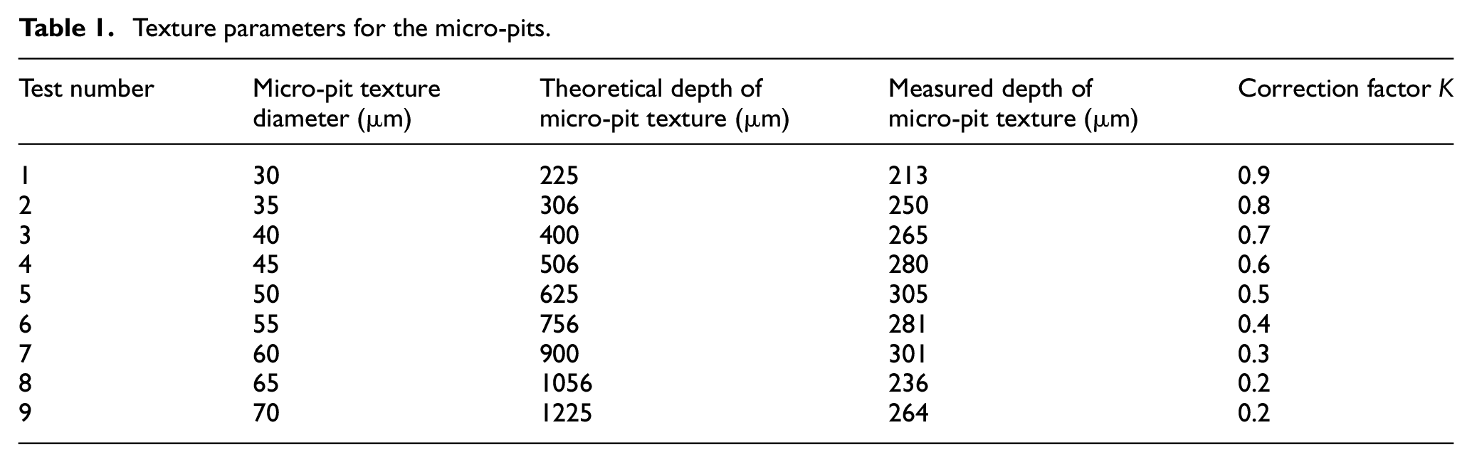
In view of the fiber laser error and the influence of the laser on the properties of the material, we introduced a correction coefficient, K. The relationship between the correction coefficient for different micro-pit diameters is shown in Figure 4. The theoretical calculations and experimental results show that as the diameter of the micro-pits increases, the ratio between the theoretical value and the experimental value (i.e. K) decreases linearly. As a result, equation (5) can be rewritten as


Test results for the micro-pit parameters.
The value range of K is 0.2–0.9.
As this article has established a relationship between micro-pit diameter and depth, this enables the cutting performance of micro-textured ball-end milling cutters to be obtained solely based on the diameter of the micro-pits on. Thus, the depth of the micro-pits is not directly considered as an influencing factor because it is implicitly captured by the diameter.
Mechanical model for the cutting edge
During the milling process, the cutting resistance of the workpiece acting against the cutter’s teeth, F, can be decomposed into the principal cutting force Fc, the radial force Fcn, and the axial force F0 (see Figure 5(a)). An axial force is produced because the cutting edge follows a helical trajectory with a helical angle, ω, to the axis of the cutter. The larger ω is, the greater the axial force (see Figure 5(b))

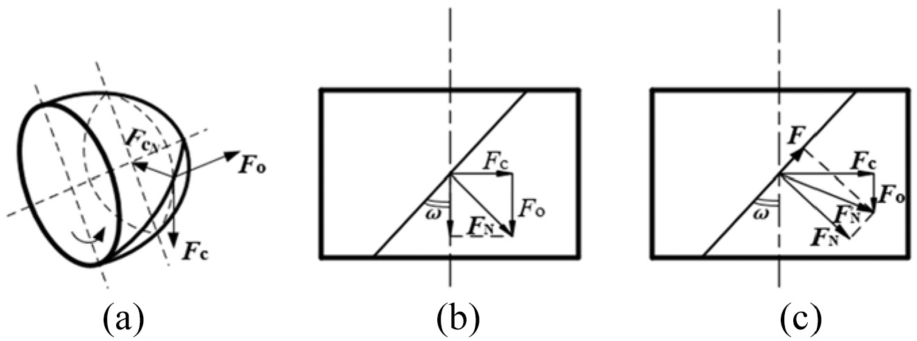
Composite forces constituting milling resistance for a helical cylindrical milling cutter (a) Schematic diagram of each component of the workpiece acting on the cutter teeth, (b) Schematic diagram of axial force generation and (c) Diagram of comprehensive force.
The above equation does not take into account the friction force, FT, of the chip flowing out along the helical front face of the cutting tool. FT works in the opposite direction along the axis to the axial force, F0, thus offsetting part of the axial force, as shown in Figure 5(c). Taking into account the counter-effect of the friction force, the axial force can be calculated using the following formula

The axial force,

The area of this micro-element,

Assuming


where

Section of the cutting layer and its area.
To solve the principal cutting force, Fc, the force for the length of the micro-element, dx, at the cutting edge x will be as follows

As can be seen from Figure 6

Entering the value of dAx into the equation, we get

where kc is the unit cutting force.
As the cutting thickness increases, the unit cutting force decreases; therefore

where C is a coefficient relating to the metal being processed and the working conditions, and y is an index that will depend on the material of the workpiece, the degree of tool wear, and the duration of the milling. In this instance, y = −0.2 to −0.4. Therefore

Substituting equation (9) into equation (16), we get

Rewriting equation (12) in the form of equation (18) gives

When the contact angle between the cutter and the cutting layer is less than 45°, the following approximation can be used

If M = ψx1,
Therefore

Taking the integral of the whole cutting edge, the principal cutting force for the whole cutting edge will be given as follows

In Figure 6, it was seen that

where B is the width of the cutting layer (mm), which refers to the part of the workpiece to be removed.
Thus

Mechanical model for a blunt circular edge
Limitations in tool preparation technology or the strength of the cutting edge during actual machining usually result in there being a blunt circular edge to the cutting tool. Even after grinding, and even if the edge is very sharp, it always retains a blunt circular radius to some degree. In actual use, the cutting edge also becomes blunt quite quickly. The simulation shows that the radius of the blunt edge has the greatest influence on the cutting performance of the tool, so it is very necessary to establish a milling force model under the action of the blunt edge.
During milling, the actual cutting radius will initially become smaller and then increase as it adopts a blunt circular shape. As shown in Figure 7, it can be seen that
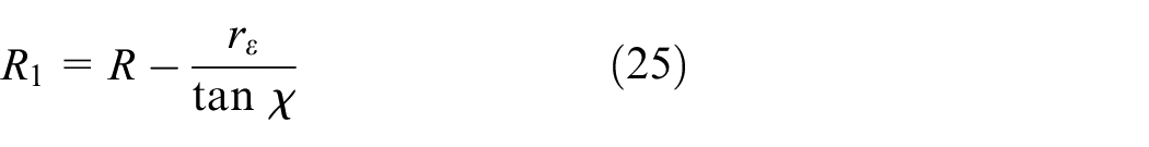

where R is the theoretical cutting radius, R1 is the actual cutting radius, and

The blunt radius of the cutting edge.
It is known that

Translating equation (26) into the form of equation (27), we get
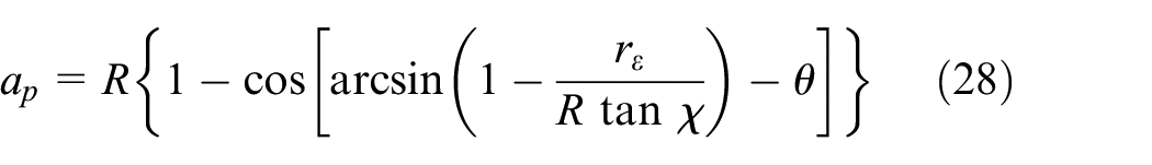
Equations (9) and (28) can now be rewritten in the form of equation (24), to give the theoretical milling force,

From equation (29), it can be seen that the milling force will decrease when the blunt radius rε is introduced and other variables are unchanged. This proves that the radius of the blunt circular cutting edge will have an effect on the milling force. As the cutting force changes, the milling temperature will also change. When the blunt cutting edge is adopted, the structural strength of the cutting tool will be increased, the wear of the cutting tool will be reduced, and the milling force will be reduced.
Mechanical model for a chamfered edge
Another kind of edge that can be encountered is a negative chamfer. Along the main cutting edge, a narrow negative antegrade plane can be produced. This is a negative chamfer. A negative chamfer can increase the strength of the blade and improve its capacity to dissipate heat, thus increasing the service life of the tool. When a negative chamfered edge is used for milling, the maximum cutter radius is less than it would be without the chamfer (see Figure 8). For this kind of edge, the relationship between the theoretical cutting radius, R, and the actual cutting radius, R1, is as follows


A micro-textured ball-end milling cutter with a negative chamfered edge.
When milling titanium alloy with a micro-textured ball-end milling cutter with a negative chamfered edge, there are two possible variations in the cutting depth, as follows:
1. When ap < b cos ι. Here, the actual cutting radius,


where b is negative inverted chamfer’s width, ι is the negative angle of the inverted chamfer, and γ1 is the angle between the front cutting surface and the drawing surface.
2. When ap ≥ b cos ι. In this case, both the cutting depth ap and the actual cutting radius R1 show a transient increase. The actual cutting depth is ap – b cos ι at the start of the cutting process. It then gradually changes to ap. R1 will gradually change from what is shown in equation (33) to what has already been demonstrated in equations (4)–(26)

R 1 reaches its maximum value after a brief increase, at which point the cutting process is mainly accomplished by the increased cutting radius. From equations (24), (27), and (32), the milling force model for a negative inverted chamfer edge can be represented as follows

where

can be simplified as
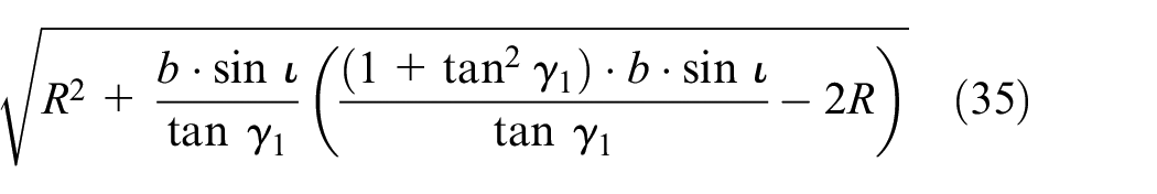
From equation (35), it can be seen that
To sum up, both a blunt circular edge and a negative chamfered edge will have the theoretical effect of reducing the required amount of milling force. This, in turn, will lead to a reduction in milling temperature and tool wear and an improvement in the surface quality of the workpiece. This illustrates the importance of examining the effect of different shaped cutting edges on the performance of cutting tools milling titanium alloy.
Simulation and analysis of milling titanium alloy with different shaped cutting edges
Simulation boundary conditions and mesh generation
To further study the impact of different shaped cutting edges on the milling of milling titanium alloy, the theoretical analysis was subjected to a finite element simulation. The finite element model of the tool and the workpiece was based on the mathematical model presented above. When undertaking this kind of simulation, the quality of the grid has a direct effect on the accuracy of the results. To properly capture the contact conditions for the tool and the workpiece and to ensure the accuracy of the simulated cutting force, it was necessary to remove some severe distortion from the grid. The advantage of grid re-partitioning is that it can make the partitions uniform, ensuring the accuracy of the simulation and helping the calculations to converge. An adaptive mesh partitioning method was therefore used to divide the mesh so that the whole workpiece was divided into 0.1 mm units, with a minimum mesh size ratio of 1:4. A thinning pane was added near the cutting edge of the tool and the part of the workpiece surface in contact with it. The mesh size was set in the refinement pane to 0.05 mm, thus ensuring the accuracy of the simulation results, while avoiding any loss of efficiency. The partitioned mesh is shown in Figure 9.

Adaptive mesh partitioning.
To preserve the accuracy of the simulation results and keep them as close as possible to their real values, boundary conditions had to be added to the workpiece and the tool. While using deform for the grid nodes, constraints were added such that for selected surfaces, they would have no direct contact with the tool in an X, Y, or Z direction. Thus, zero degrees of freedom were assigned to the relevant nodes. Contact conditions for the tool and the workpiece were added at the same time, with the shear friction coefficient being set to 0.6 and the heat transfer coefficient to be 45, so as to be able to simulate the stress and strain when calculating the initial conditions. For this particular study, the cutting tool needed to be able to translate and rotate at the same time for two different kinds of considerations: the feed speed and the speed of rotation. Finally, the cutting tool and workpiece had to be given an initial temperature and a heat transfer surface. The initial temperature was set to be 20° at room temperature, and the heat transfer surfaces were taken to be the surface of the two different cutting edges and the surface of the workpiece.
Simulation design
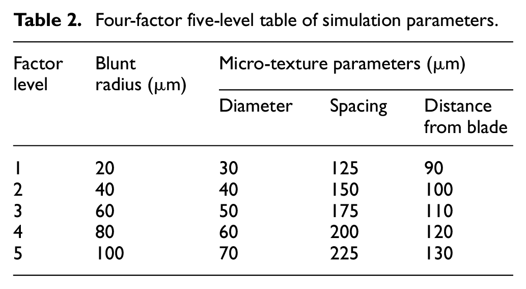
The cutting parameters used in this study were cutting speed, vc = 120 m/min; feed, fz = 0.08 mm; cutting width, ae = 0.5 mm; and cutting thickness, ap = 0.3 mm. Therefore, as an example, Figure 10 shows the micro-texture distribution where the diameter of the micro-texture was 30 μm, the spacing between the micro-pits was 125 μm, and the distance of the texture from the edge of the blade was 90 μm. Based on the above parameters, a table of four factors and five levels was designed to study the effect of the micro-pit texture on the cutting temperature and the cutting force (Table 2). From this, we were able to obtain the influence of the micro-pit diameter on the cutting performance, so micro-pit depth was not considered as a factor.

Micro-texture distribution.
Four-factor five-level table of simulation parameters.
Milling force for a blunt circular edge
Range analysis was used to process the average cutting force generated during the simulations. The resulting data are shown in Table 3. According to an extreme difference analysis of the four factors listed in the table, the order of influence of the texture parameters on the average cutting force when using a blunt circular edge was radius of the edge > micro-pit diameter > micro-pit spacing > distance from the cutting edge. Therefore, from this, we can say that the blunt radius of the edge will have the greatest influence on the average cutting force and the distance of the texture from the cutting edge will have the least effect.
Extreme difference analysis of simulated milling force under blunt circular edge.
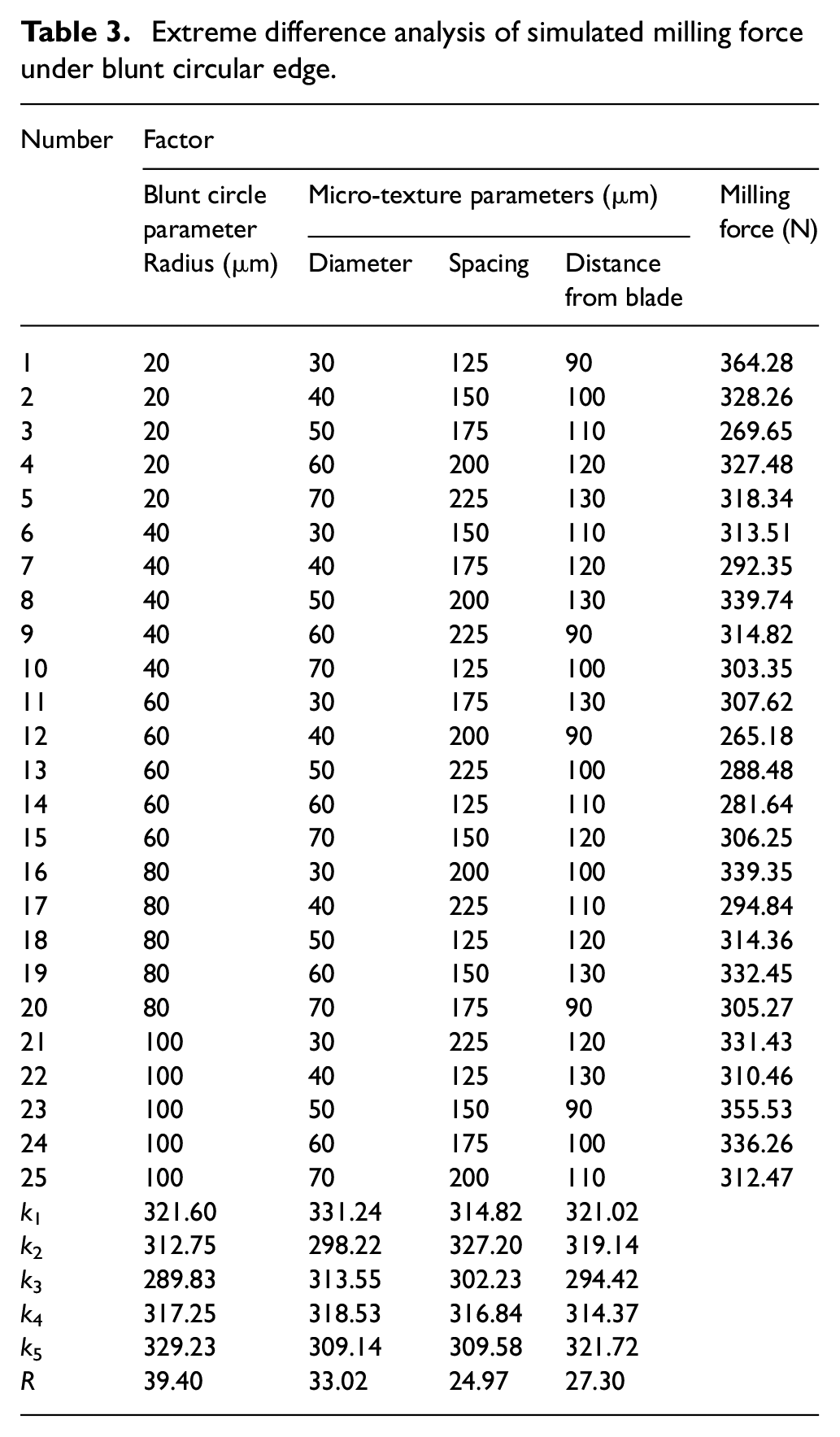
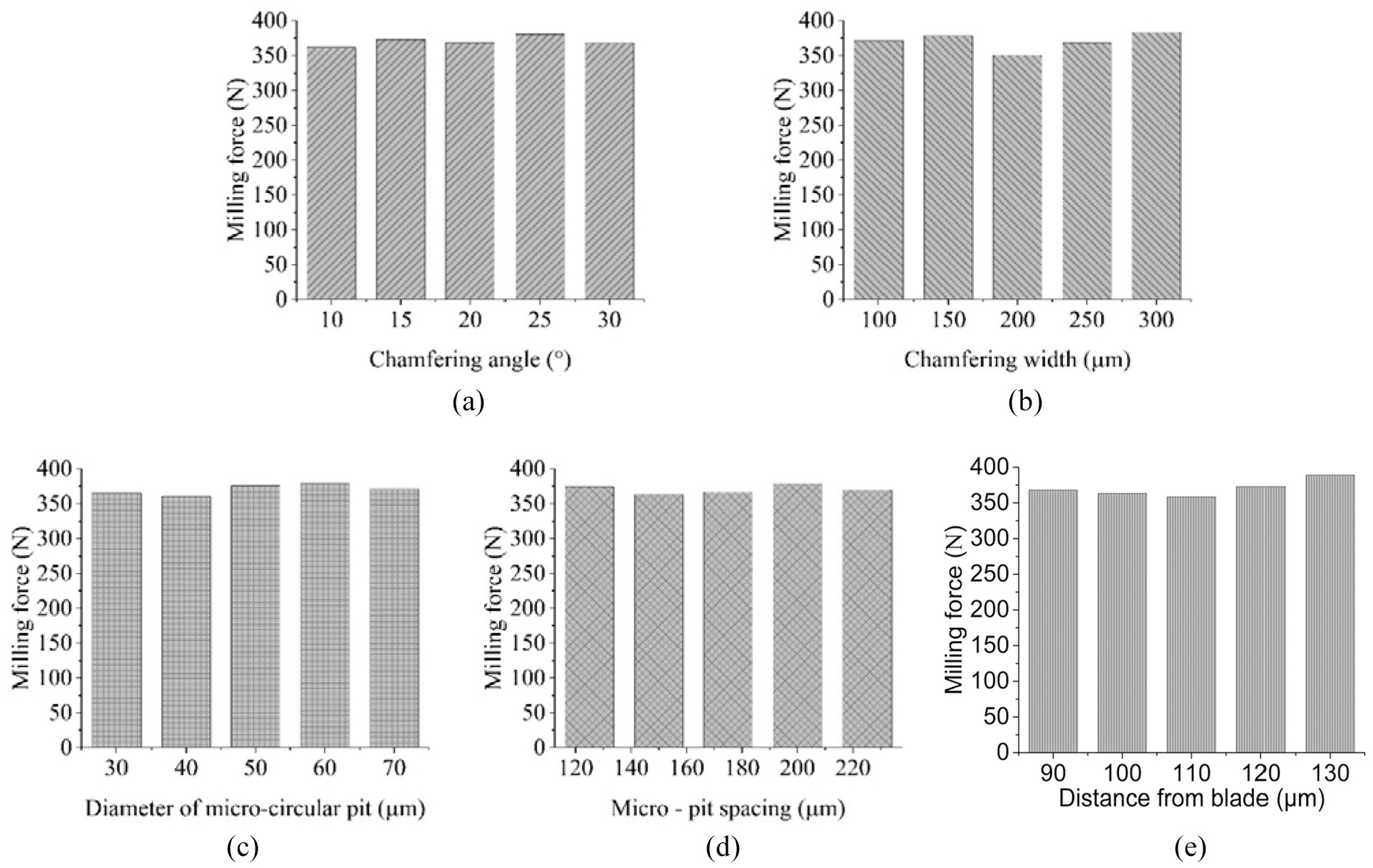
As shown in Figure 11(a), as the radius of the blunt edge increases, the average cutting force initially decreases and then increases. Figure 11(b) indicates that as the micro-pit diameter increases, the average cutting force initially decreases, then increases slightly, then decreases further, with the overall trend being a decrease. Figure 11(c) shows how an increase in the distance of the texture from the cutting edge will initially result in a decrease in the average cutting force, followed by an increase. In Figure 11(d), it can be seen that an increase in the micro-pit spacing will first bring about an increase in the average milling force, then a decrease, then another increase, and then a further decrease. Therefore, when the average cutting force is taken as an evaluation index, the optimum parameters for the micro-texture are a micro-pit diameter of 40 μm, a distance between micro-pits of 175 μm, a distance between the micro-texture and the cutting edge of 110 μm, and a blunt circular edge radius of 60 μm.

Effect of the micro-texture parameters and blunt edge parameters on the simulated milling force: (a) influence of the cutting edge radius on the simulated milling force, (b) influence of the micro-pit diameter on the simulated milling force, (c) influence of the distance of the texture from the edge on the simulated milling force, and (d) influence of the micro-pit spacing on the simulated milling force.
Milling force for a negative chamfered edge
The setting of the boundary conditions and the mesh for the simulation of milling titanium alloy with a negative chamfered micro-textured edge was the same as it was for a blunt circular edge. An orthogonal simulation experiment was designed, with the average cutting force for milling with a negative chamfered edge being subjected once again to range analysis. The related data are shown in Table 4. According to an extreme difference analysis of the six factors listed in the table, the order of influence of the texture parameters on the average cutting force when using a negative chamfered edge was the width of the negative chamfer > the distance between the texture and the cutting edge > the angle of the negative chamfer > the micro-pit diameter > the distance between the micro-pits. Therefore, from this, we can say that the width of the negative chamfered edge will have the greatest influence on the average cutting force, while the spacing of the micro-pits will have the least effect.
Extreme difference analysis of simulated milling force under negative chamfered edge.

Figure 12 shows the influence of the micro-texture parameters and negative chamfered edge parameters on the average cutting force. As shown in Figure 12(a), as the negative chamfer angle increases, there is an initial increase in the average cutting force, then a decrease, then another increase, and then a further decrease. Figure 12(b) shows that as the negative chamfer width increases, the average cutting force initially increases, then decreases, and then increases further. In Figure 12(c), it can be seen that as the micro-pit diameter increases, the average milling force first of all decreases, then increases, and then decreases again. Figure 12(d) illustrates how an increase in the micro-pit spacing results in an initial decrease in the average cutting force, followed by an increase, then a further decrease. Figure12(e) shows that an increase in the distance between the micro-texture and the cutting edge leads to an initial decrease in the average cutting force and then an increase. Therefore, when the average cutting force is taken as an evaluation index, the optimum micro-texture parameters are a micro-pit diameter of 30 μm, a micro-pit spacing of 150 μm, a distance from the cutting edge of 110 μm, a negative chamfered edge width of 200 μm, and a negative chamfer angle of 10°.
Effect of the micro-texture parameters and negative chamfered edge parameters on the simulated cutting force: (a) influence of the negative chamfer angle on the simulated milling force, (b) influence of the negative chamfer width on the simulated milling force, (c) influence of the micro-pit diameter on the simulated milling force, (d) influence of the micro-pit spacing on the simulated milling force, and (e) influence of the distance of the texture from the edge on the simulated milling force.
Experimental verification
To assess the viability of the milling force models established above, physical cutting experiments were conducted so that the results could be compared. The experimental results are presented in the following.
Assessment of the blunt circular edge milling force model
From the range of four factors measured during the physical experiments that are presented in Table 5, the order of influence of the micro-texture and blunt circular edge parameters on the average cutting force can be determined as follows: the radius of the edge > the micro-pit diameter > the micro-pit spacing > the distance between the texture and the cutting edge. Therefore, the experimental data suggest that the radius of the blunt circular edge will have the greatest influence on the average cutting force, while the distance of the texture from the cutting edge will have the least effect.
Extreme difference analysis of milling force experimental data for blunt circular edge.
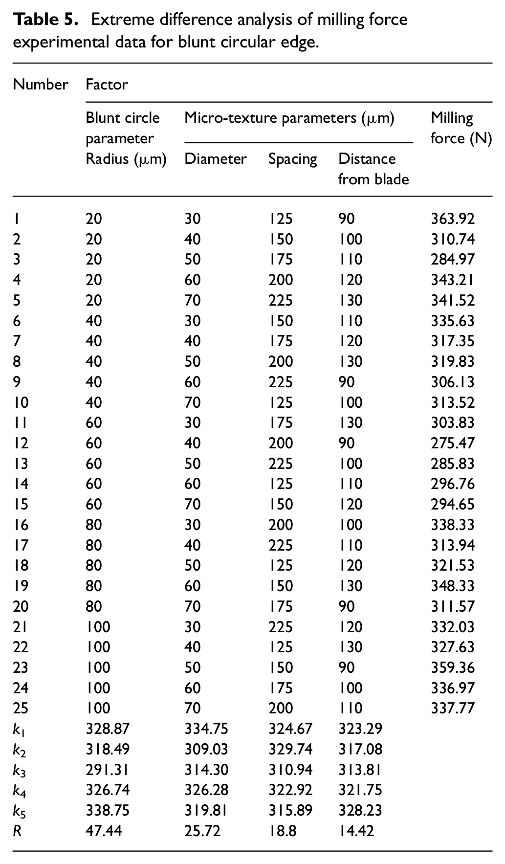
Figure 13 shows the relationship obtained from the cutting test between the micro-texture parameters and blunt circular edge parameters and the average cutting force. As shown in Figure 13(a), when the radius of the blunt circular edge increases, the average cutting force initially decreases sharply and then increases slightly. The reason for this is that when the radius of the cutting edge is 20 μm, the cutting edge is relatively sharp, which makes it prone to significant wear, leading to a skipping phenomenon. When the radius of the cutting edge is greater, its structural strength increases, helping it to resist wear and reducing the necessary milling force.

Influence of the micro-texture and cutting edge parameters on the average milling force: (a) effect of the blunt circular edge radius on the milling force, (b) influence of the micro-pit diameter on the milling force, (c) influence of the micro-pit spacing on the milling force, and (d) influence of the distance between the micro-texture and the edge on the milling force.
Figure 13(b) shows that as the micro-pit diameter increases, the average cutting force initially decreases, then increases, and then decreases again. This is because when the diameter of the micro-pit increases, it becomes more effective at capturing chips and abrasives, thus reducing the abrasive wear and increasing the wear resistance. This leads to a reduced milling force. As the diameter of the micro-pit continues to increase, its shape becomes closer to a plane, and the phenomenon of “secondary cutting” at the edge of the micro-pit decreases, so the milling force continues to decrease. The anti-wear and anti-friction effect of the micro-texture exceeds the effect of the “secondary cutting,” so the milling force continues to decrease as the diameter of the micro-pit gets bigger.
In Figure 13(c), it can be seen that as the micro-pit spacing increases, the average cutting force first of all increases, then decreases, and then increases again before a further decrease. When the micro-pits are closer together, the amount of micro-texture in the tool–chip contact area is greater, which increases the surface roughness of the tool. At this point, the effect of the micro-texture is less than the friction caused by the roughness of the tool’s surface. As the micro-pit spacing increases, the average milling force increases as well until, at a certain point, the roughness of the rake face decreases and the effect of the micro-texture comes to the fore, making the average milling force decreases. When the micro-pit spacing continues to increase, however, the extent of the micro-texture in the tool–chip region reduces to the point where the milling force increases again. As the tool–chip contact area increases, however, the number of micro-pits is further decreased, reducing the roughness of the tool’s surface, so the milling force decreases again.
Figure 13(d) shows how the average cutting force decreases, then increases, as the distance between the micro-texture and the cutting edge is increased. The reason for this is that as this distance increases, the micro-texture in the close contact area plays a greater role in reducing the wear and friction, so the amount of cutting force is decreased. As the distance continues to increase, however, it becomes less pronounced and the milling force gradually increases. Therefore, it can be seen that when the average cutting force is taken as an evaluation index, the optimum micro-texture parameters are a micro-pit diameter of 40 μm, a micro-pit spacing of 175 μm, a distance of 110 μm between the micro-texture and the cutting edge, and a blunt circular edge radius of 60 μm.
Assessment of the negative chamfered edge milling force model
The equipment, processing parameters, and workpiece size for the experimental milling of titanium alloy with a negative chamfer edged micro-textured ball-end milling cutter were all the same as those used for the experiments with a blunt circular edged tool. The order of influence of the micro-texture and negative chamfered edge parameters on the average milling force was determined according to the magnitude of the extreme difference for the six factors listed in Table 6. The order was the negative chamfer width > the distance of the micro-texture from the cutting edge > the negative chamfer angle > the micro-pit diameter > the micro-pit spacing. Therefore, the width of the negative chamfered edge has the greatest influence on the average milling force and the micro-pit spacing has the least.
Extreme difference analysis of milling force experimental data for negative chamfered edge.

Figure 14 shows the relationship between the micro-texture and negative chamfered edge parameters and the average cutting force obtained from the cutting experiments. As shown in Figure 14(a), as the width of the negative chamfer increases, the average milling force initially increases as well, then decreases, then continues to increase. The reason for this is that when the width of the negative chamfer is between 100 and 150 μm, the change in the tool–chip contact length leads to an increase in chip curling deformation and thus the cutting force. When the width of the negative chamfer is between 150 and 200 μm, there is more friction between the tool and the chip and the temperature rises, leading to a softening of the material being processed. However, as the developing chips on the negative chamfer become softer and are replaced by actual chips, the milling force is reduced significantly. As the chamfer width continues to increase, the negative chamfer becomes the rake face and the length between the tool and the chip remains stable, leading to a further, slow reduction in the milling force.

Influence of the negative chamfer and micro-texture parameters on the experimental milling force: (a) influence of the negative chamfer width on the experimental milling force, (b) influence of the negative chamfer angle on the experimental milling force, (c) influence of the micro-pit diameter on the experimental milling force, (d) influence of the micro-pit spacing on the experimental milling force, and (e) influence of the distance from the cutting edge on the experimental milling force.
In Figure 14(b), it can be seen that as the negative chamfer angle increases, the average milling force initially increases and then decreases. When the negative chamfer angle increases from 10° to 25°, the wedge-shaped angle of the cutting edge increases along with the negative chamfer angle. This increases the chip deformation, so the cutting force tends to increase as well. When the negative chamfer angle increases from 25° to 30°, the cutting force decreases. This is because, when a negative chamfered tool is used, the cutting is mainly concentrated in the negative chamfer area. As the negative chamfer angle increases, the contact area between the tool and the workpiece increases as well, resulting in a large amount of heat energy being generated, which increases the rate at which the metal softens, so the cutting force tends to decrease.
Figure 14(c) shows that as the micro-pit diameter increases, the average milling force first of all decreases, then increases, and then decreases again. When the micro-pit diameter increases from 30 to 50 μm, the number of micro-pits in the tool–chip contact area decreases, so the surface roughness of the tool decreases, allowing the anti-wear and anti-friction properties of the micro-texture to come into play. When the micro-pit diameter increases from 50 to 60 μm, the number of pits decreases, reducing the anti-wear and anti-friction effect and making the milling force increase. As the diameter increases from 60 to 70 μm, the number of micro-pits continues to decrease, but so does the surface roughness of the tool, reducing the amount of friction, so the milling force decreases.
As shown in Figure 14(d), when the micro-pit spacing increases, the average milling force starts off by decreasing, then it increases, before decreasing again. When the distance between the micro-pits increases from 125 to 175 μm, the overall number of micro-pits decreases, so the roughness of the tool surface decreases as well, leading to a reduction in the friction force on the rake face. When the distance between the micro-pits increases from 175 to 200 μm, the number of micro-pits in the tool–chip contact area decreases, limiting the anti-wear and anti-friction effect and making the milling force increase. When the distance between the micro-pits increases from 200 to 225 μm, the number of micro-pits further decreases. At point m, as the number of micro-pits continues to decrease, the roughness of tool rake face decreases too, leading to a reduction in the friction on the rake face and a decrease in the milling force.
Figure 14(e) shows that as the distance of the micro-texture from the cutting edge increases, the average milling force initially decreases and then increases. As the distance increases from 90 to 120 μm, the cutting force decreases because the micro-texture is getting farther away from the cutting edge, so the strength of the cutting edge increases. At the same time, the presence of the micro-texture in the contact area gives full play to the anti-wear and anti-friction effect, helping the cutting force to decrease. When the distance continues to increase to 130 μm, the micro-texture gradually moves out of the tool–chip contact area, weakening the anti-wear and anti-friction performance and leading to a gradual increase in the cutting force.
Therefore, Figure 14 shows that when the average cutting force is taken as an evaluation index, the optimal combination of parameters is a micro-pit diameter of 50 μm, a micro-pit spacing of 175 μm, a distance between the micro-texture and the cutting edge of 120 μm, a negative chamfer edge width of 200 μm, and a negative chamfer angle of 10°.
Conclusion
This article mainly studies the influence of different cutting edge forms and micro-texture parameters on milling force when the tool is milling titanium alloy. First, the milling mechanical model under the action of blunt and chamfered edges is established through theoretical analysis. Then, the influence law of different cutting edge parameters and micro-texture parameters on milling force is obtained by simulation and experiment. Finally, the milling force is taken as the evaluation standard, and the optimal combination of the optimal parameters of different cutting edges and micro-texture parameters is finally optimized. The following conclusions were obtained from the study:
From the theoretical model, it can be deduced an increase in the radius of a blunt circular edge rε, the width of a negative chamfer b and a remapping of the negative inverted angle ι, will all reduce the milling force.
Through the simulation analysis and experimental verification of the milling process under different cutting edges, when using a blunt circular cutting edge, the order of the influence of various parameters on the average cutting force was as follows: the radius of the blunt circular edge > the micro-pit diameter > the micro-pit spacing > the distance of the micro-texture from the cutting edge. As the radius of the blunt circular edge increases, the average milling force initially decreases sharply, then slightly increases. When the micro-pit diameter increases, the average milling force decreases first of all, then increases, then decreases again. With an increase in the micro-pit spacing, the average milling force initially increases, then decreases, then increases again, then decreases further. As the distance of the micro-texture from the cutting edge increases, the average milling force first decreases and then increases. When using a negative chamfered edge, the order of influence of the various parameters on the average milling force was as follows: the negative chamfer width > the distance from the cutting edge distance > the negative chamfer angle > the micro-pit diameter > the micro-pit spacing. As the width of the negative chamfer increases, the average cutting force increases as well. When the negative chamfer angle increases, the average milling force increases first of all, then decreases. An increase in the micro-pit diameter results in the average milling force initially decreasing, then increasing, then decreasing again. With an increase in the micro-pit spacing, the average milling force first decreases, then increases, and then decreases again. As the distance from the cutting edge increases, the average milling force first of all decreases and then increases.
For a blunt circular edge, if the average milling force is taken as an evaluation index, the optimal micro-texture parameters are as follows: a micro-pit diameter of 40 μm, a micro-pit spacing of 175 μm, and a distance from the cutting edge of 110 μm, with a blunt circle radius of 60 μm. For a negative chamfered edge, the optimal parameters are a micro-pit diameter of 50 μm, a micro-pit spacing of 175 μm, and a distance from the cutting edge of 120 μm, with a negative chamfered edge width of 200 μm and a negative chamfer angle of 10°.
Footnotes
Handling Editor: James Baldwin
Declaration of conflicting interests
The author(s) declared no potential conflicts of interest with respect to the research, authorship, and/or publication of this article.
Funding
The author(s) disclosed receipt of the following financial support for the research, authorship, and/or publication of this article: This work was supported by The National Natural Science Foundation of China (grant number 51875144) and Construction of Scientific Research Collaborative Innovation Platform Advanced Manufacturing Intelligent Technology.