
Abstract
In the milling of titanium alloy, the distribution of milling force and its related law of change seriously affect the physical properties of workpiece materials, the stress distribution on a cutter’s rake face and the interaction between the workpiece, the cutter and the chip. This article reports on a study of the stress field distribution under the conditions of anti-friction and anti-wear when cutting titanium alloy with a micro-textured ball-end milling cutter. Milling test data were used to establish empirical models of milling force and the contact area between the cutter and the chip. Based on this, the force density function of the cutter coordinate system was obtained and the equivalent stress and displacement of the cutter were simulated and analyzed. This in turn provided the means to acquire the instantaneous stress and strain relating to the cutter at any time. Analysis of the simulation results shows that the position in which the stress and strain are concentrated on the cutter is consistent with actual processing. This confirms the accuracy of the force density function and provides the basis for further study of thermo-mechanical coupling behaviors when engaged in using micro-textured ball-end milling cutters for the cutting of titanium.
Introduction
In the high-speed milling of titanium alloy, the distribution of milling force and associated law of change seriously affect the physical properties of the workpiece, the distribution of stress on the rake face of the cutter and the interaction between the workpiece, the cutter and the chip. An uneven distribution of milling force results in a significant increase in friction, deformation of the workpiece and a local rise in temperature.1,2 Study of the stress field created by milling titanium alloy with cutters such as carbide ball-end milling cutters can therefore help with identifying how to reduce wear on the cutter and obtain better machined surface integrity. However, as cutting titanium alloy is a highly dynamic and nonlinear process, the addition of micro-textures to cutters can have a further impact on the stress field during milling. 3 To investigate this, a force and density function can be used to directly simulate the distribution of the stress field.4,5 In that case, the stress field when milling titanium alloy with micro-textured carbide ball-end milling cutters was analyzed in the research reported in this article, so as to establish the force density function and the laws shaping its influence upon the cutting process. This then provides the basis for studying thermal–mechanical coupling behaviors in high-speed cutting.
There can be many reasons for an uneven distribution in cutter force, so the distribution of stress fields during cutting has been studied by a number of researchers. Cheng Y, for instance, have studied the force density function associated with three-dimensional (3D) complex groove milling blades. Using an orthogonal milling experiment, they were able to establish the force density function for the rake face. Analyzing this in turn, it was found that the stress on the blade was mainly distributed around the main tool edge and concentrated near the cutter nose during the cutting process. 6 Zhang took the milling force density function as a boundary condition and used this to study and simulate the stress field on the rake face in a similar circumstance of using a 3D complex groove milling cutter. Here, it was found that the negative shear at the moment of cutting out during milling was a unique phenomenon in an interrupted cutting process. The slip deformation and plastic deformation of the negative shear caused significant stress at the cutter nose, putting it in a dangerous state with an elevated risk that the cutter would break. The rake angle and relief angle of a milling blade can fundamentally change the situation.7,8 Kim and Heikkala have simulated the static and dynamic forces involved in milling. By taking into consideration the machine tool and fixture, they established a mathematical model of the component force of milling cutters. A range of cutting experiments with different milling cutters and workpiece materials were carried out and consistent results were obtained.9,10 Sun et al. have simulated the micro-milling of aluminum alloy and examined the influence of blunt tool edge radius using ABAQUS. The cutter rotation angle at different cutting speeds, the blunt tool edge radius and the stress distribution at different feed rates were all studied, thereby founding finding a specific research interest in micro-milling machining mechanisms. 11 Taking into account the characteristics of high-speed face milling processes, models of the stress fields for two types of high-speed face milling cutters have been proposed by Zheng and Jiang. Using finite element analysis of the stress field for high-speed face milling cutters, a law of influence on stress fields under the conditions of high rotational speed for cutter structures, cutter sub-assemblies and the fixing rake of blades was acquired. This foundational study provided a complete reconstruction and analysis of the stress field in its cutter model, thus establishing the core model of evaluation for the dynamic cutting performance of high-speed face milling cutters. The results of high-speed face milling experiments and frequency spectrum analysis of dynamic cutting forces indicate that high-speed face milling cutters with a fixed rake angle of zero degrees and fewer sub-assemblies can produce better high-speed dynamic cutting performance. 12 Li has focused on the problem of blades being prone to breakage and failure for turning processes with materials that are difficult to machine, such as stainless steel 1Cr-18Ni-9Ti and high-strength steel 2.25Cr-1Mo-0.25V. Here, the force and temperature distribution at the rake face of the cutter was the main object of research. The force density function of the rake face of an H-groove carbide cutter was established. This served as a boundary condition for finite element analysis of the stress and temperature field of the blade in turning. It also provides the basic reference data for offsetting the bond damage mechanism. 13 Pan et al. studied the effect of dynamic evolution of microstructures on processing force. A material-microstructure-mechanics-affected machining scheme is proposed to account for the influence of material microstructural evolution on cutting mechanics. An explicit calculation of material microstructural evolution path is provided. To blend the material microstructure states into the thermo-mechanical coupling process, the material microstructure terms are introduced into the traditional Johnson–Cook model. As an application, the machining forces and the average grain size are predicted in the orthogonal turning of titanium alloys. This method provides a more comprehensive way to explore microstructure–thermo-mechanical coupling in the machining process. 14 Qiang et al. studied the cutting performance of a micro-textured ball-end milling cutter in milling titanium alloy. A multilevel fuzzy comprehensive evaluation approach based on multi-objective decision theory is used to assess tool cutting performance during the machining of titanium alloy. This includes an exponential scale of Analytical Hierarchy Process (AHP) weights for each index. They studied two different kinds of cutting tools, one with an applied micro-texture, and conducted a comprehensive evaluation of their performance when engaged in the ordinary milling of titanium alloy. This was based on surface roughness, surface hardening, chip formation and tool wear. We also undertook a comparison of the required cutting force and cutting temperature. The results show that, in the process of cutting titanium alloy, the micro-texture of the surface has an anti-wear effect and stores impurities. This can improve a cutting tool’s workpiece and chip contact environment as well as its actual processing performance. The overall evaluation value for a micro-textured ball-end milling cutter was found to be 0.62. Against this, the value for a common milling cutter was 0.38. These results form an important basis for improving the machinability of titanium alloy. 15
While the above studies have been effective, the research regarding stress fields remains small. Therefore, based upon an examination of anti-wear and anti-friction mechanisms for micro-textures, this article will be analyzing the stress distribution for micro-textured ball-end milling cutters engaged in milling titanium alloy. Initial experiments provided the empirical formulas for milling force and the contact areas between the cutter and the workpiece. The force density function of the milling force was then established. Through analysis of the load boundary conditions, a simulation of the stress field was carried out and analyzed using the ANSYS Workbench. This then provided the basis for a study of cutter structure optimization and the thermo-mechanical coupling behavior of micro-textured ball-end milling cutters when milling titanium alloy.
Test milling of titanium alloy with the micro-textured ball-end milling cutter
Purpose of the test
To study the thermo-mechanical coupling behavior of micro-textured ball-end milling cutters when milling titanium alloy, we first of all wanted to examine changes in milling force over time. We therefore set up a platform to measure changes in milling force during a milling process. This then provided the basic data for uncovering the force density function. The specific aspects of the test and their purpose were as follows:
Calculating the cutting circle for milling titanium alloy with a micro-textured ball-end milling cutter and then measuring the milling force over a milling cycle. The purpose of this was to fit the function of milling force changes over time.
Measuring the milling force values for each set in an orthogonal experiment by changing the cutting parameters (cutting speed, cutting depth and feed rate). The common equations for the milling force and the cutting parameters were then established and the empirical formulas for cutting were fitted. This provided the basis for studying the force density function of the rake face.
The relationship between the contact length and the feed rate as well as between the contact width and the cutting depth was studied using an orthogonal cutting test to establish the relevant empirical formulas. This provided further basis for studying the force density function.
Test equipment
The milling force was measured with a Kistler 9257B dynamometer with a response frequency of 5000 Hz. The dynamometer consisted of four sensors designed to measure three forces. These were mounted between the substrate and the top plate, an area of strong rigidity. The data acquisition system was a Donghua DH5922_1394 signal test and analysis system. This contained the signal conditioner (strain, vibration and other conditions), a direct current (DC) voltage amplifier, a low-pass filter, an anti-mixing filter, a 16-bit A/D converter, the sampling control and all of the computer communication hardware. This also provided control and analysis software for the operation system, which was a computer-based intelligent dynamic signal test analysis system that provided for usability. First of all, the dynamometer was fixed on the computer numerical control (CNC) machine tool and connected to a dynamometer oscilloscope. Second, the three channels from the dynamometer oscilloscope were connected to the DH5922_1394 signal and test channels 1, 2 and 3, to measure the three directions of the milling force (see Figure 1). Finally, the DH5922_1394 signal test and analysis system was connected to the computer with data lines to collect the three directions of the milling force. The test platform is shown in Figure 1 and the test acquisition system is shown in Figure 2.
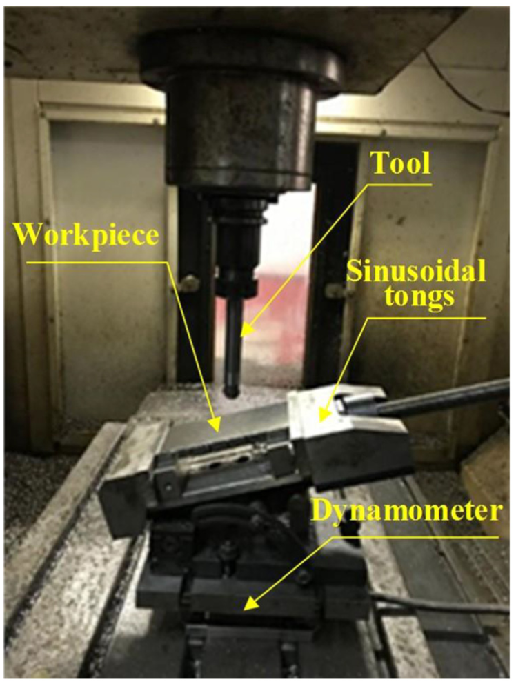
Test platform.
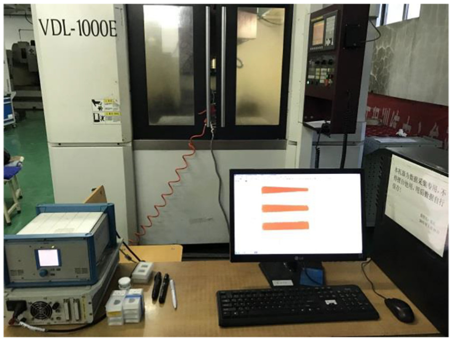
Test acquisition system.
The test material was titanium alloy TC4. The workpiece was made by wire electrical discharge machining (WEDM) with an inclined angle of 15°. The micro-textured ball-end milling cutter used in the test had a diameter of 20 mm, with the micro-texture etched into the rake face. The shape of the micro-texture was micro-pits with a diameter of 50 μm and a depth of 35 μm. The distance from the micro-pits to the cutting edge was 120 μm and the distance between any two adjacent micro-pits was 120 μm, with an offset angle of 1.007°. When plane milling is being conducted, the cutter nose participates in the cutting and the line speed is always zero. This produces wear on the cutter nose, reducing the cutter life and affecting the surface quality of the workpiece being processed. Some researchers have found that when the inclined angle of the workpiece is 15°, the cutter can achieve a better cutting performance. This is why the workpiece was positioned at an angle of 15° for the test. The processing mode was down milling.
Experimental design
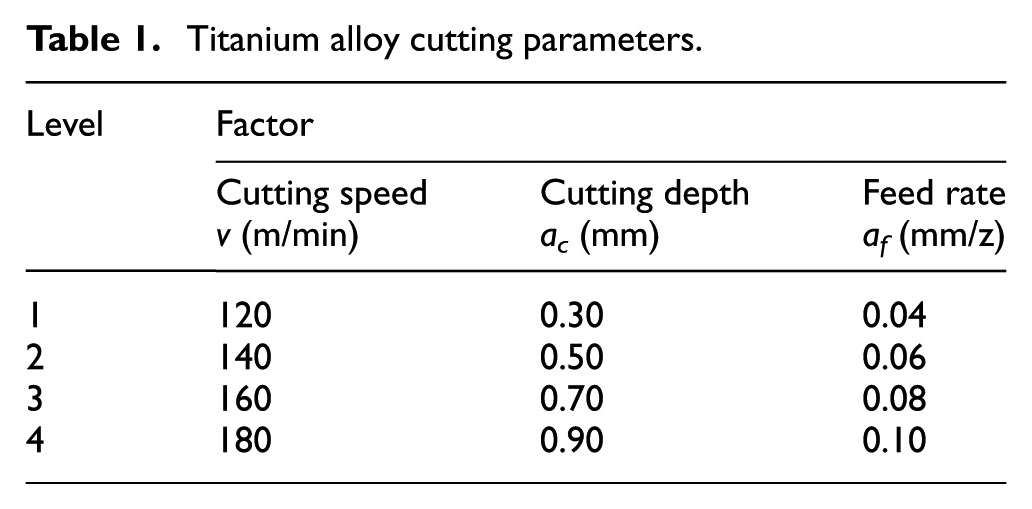
The milling experiment was conducted as an orthogonal test. The milling process temperature and changes in force over time, together with the contact length and width changes according to the feed rate and cutting depth, were studied by changing the cutting parameters in the milling process. The orthogonal test was designed to include three factors (the cutting speed, the cutting depth and the feed rate), which contained four levels, as shown in Table 1. The orthogonal table is L16 (45).
Titanium alloy cutting parameters.
From the orthogonal table, it can be seen that there were 16 tests. The total length of feed was a layer in each test with a group of cutting parameters. Six points were set at an average distance along the length of the workpiece and a set of cutting force values were measured at each point. The cutting forces under the group of cutting parameters in the three directions X, Y and Z were calculated by calculating the average value of the six groups of data in each layer. This provided the basic data for the empirical formulas. At the same time, the milling temperature and force changes over time were measured at a central location.
Analysis of the milling force test results
When a cutter is cutting into a workpiece, the waveform mutates. Therefore, when dealing with milling force data, it is necessary to capture the waveform of the milling force, intercept the beginning signal and save the smooth cutting signal. In the processing of the data, the average values of the smooth signal were calculated. This represents the cutting force. The sampling frequency of the dynamometer was 5000 Hz, so the milling force was collected every 0.0002 s. In this way, 16 groups of milling forces were obtained during the orthogonal test. Taking one group as an example, the cutting parameters n = 2729 r/min, ac = 0.7 mm, af = 0.08 mm/z and the milling force for the X, Y and Z directions over a milling cycle are shown in Table 2.
Milling forces for a micro-textured ball-end milling cutter over a milling cycle.
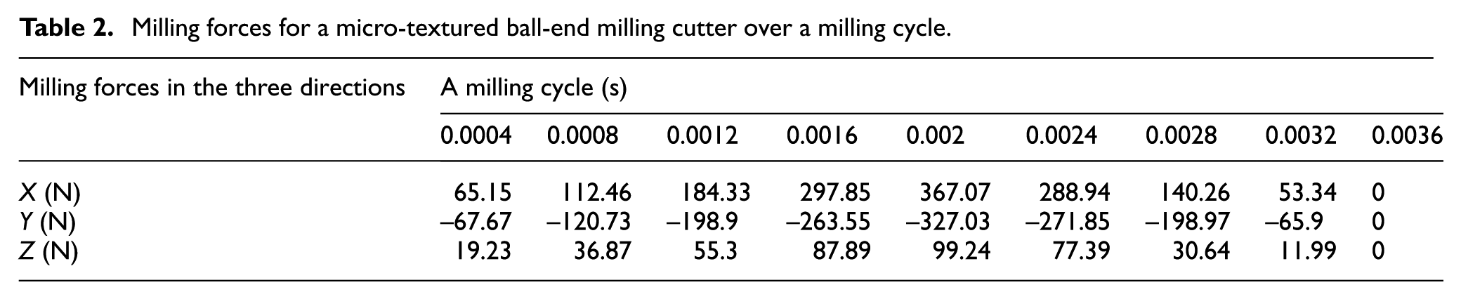
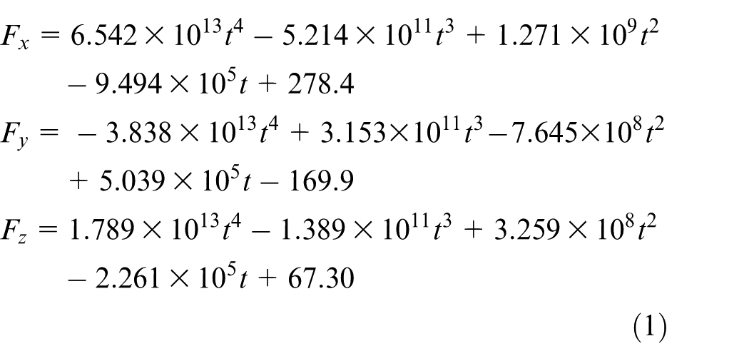
The data for the three directions of milling force were fitted using the MATLAB software and the equations for changes in milling force over time were fitted in the three directions. The program was written to fit the equations across a cutting cycle. This then provided the foundation of the force density function for the micro-textured ball-end milling cutter
Analysis of the test results for the contact length and width between the cutter and the chip
When cutting titanium alloy, the contact area has a very important impact on the temperature field calculations for the second deformation zone, tool wear and the distribution of the cutter milling force. The theoretical formula for calculating the contact area in the cutting process is very complicated and cumbersome. In that case, a contact pattern method was used to study the contact area.
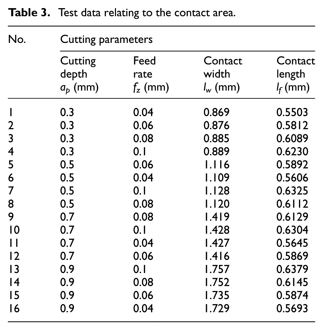
The contact area was observed using a super-depth microscope and the contact length and width were measured, as shown in Figure 3. It can be seen from the figure that the contact area can be treated approximately as a rectangle. The contact width lw in the direction of the tool edge of the cutter becomes longer as the cutting depth ac increases. The data for the contact length and width measured by the super-depth microscope are shown in Table 3.
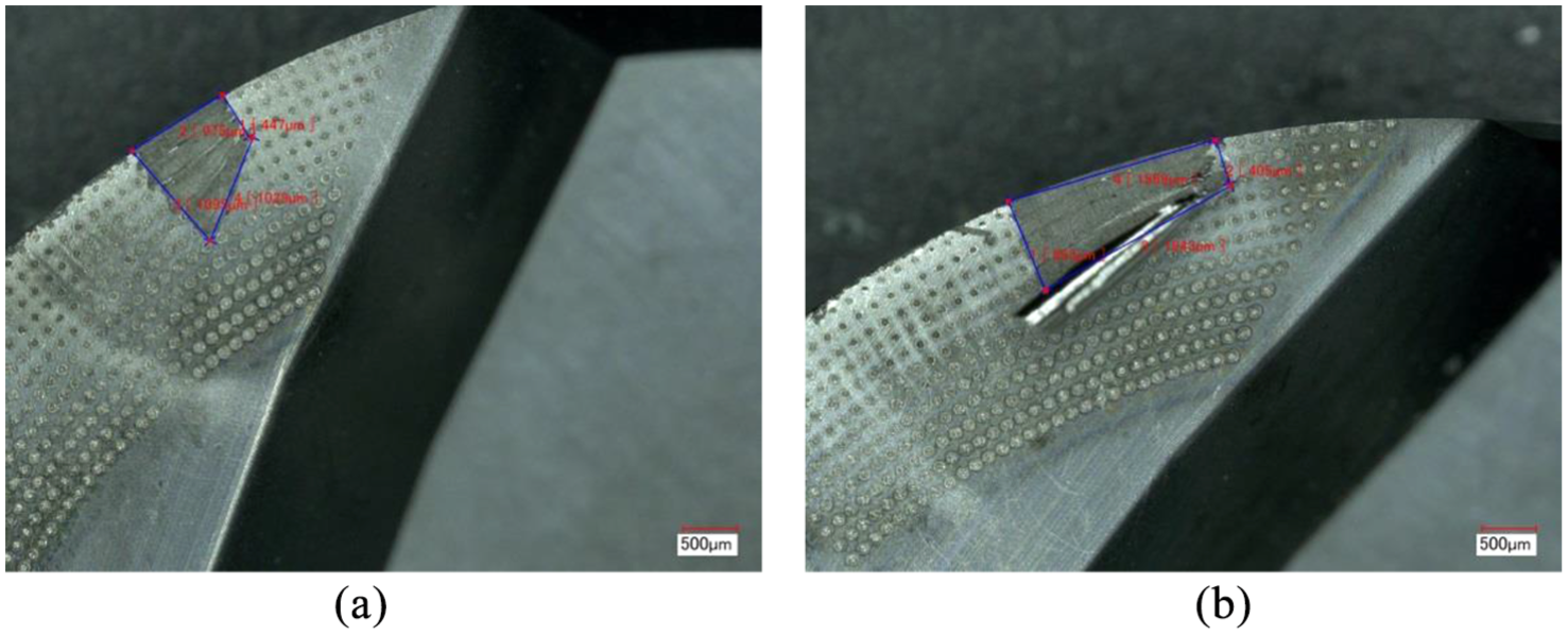
Test pictures of the contact area: (a) cutting depth ap is 0.3 mm and (b) cutting depth ap is 0.7 mm.
Test data relating to the contact area.
The force density function
The empirical formula for the milling force
In high-speed milling, intermittent cutting is the most widely used process. For milling titanium alloy with ball-end milling cutters, this is typically interrupted cutting, which has a specific cutting cycle.16,17 The cutting cycle is considered to be the time from cutting into the workpiece to the cutting out of the workpiece at the tool edge. The cutting cycle determines not only the final state of the cutting out, but also the size and direction of the instantaneous milling force when the ball-end milling cutter cuts out, thus affecting the distribution of the stress field on the rake face. Therefore, for milling cycle T, the cutting angle
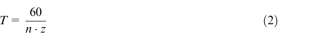
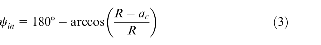

where n represents the spindle speed (r/min), z represents the number of teeth on the tool edge and R represents the tool edge radius.
The selection of the cutting parameters also has a great impact on the stress distribution on the rake face. Among the three cutting factors, the cutting speed indirectly influences the cutting force by changing the friction state between the chip and the rake face, so it can be neglected. However, the influence of the cutting depth and feed rate on the cutting force is both direct and significant. The relationship between the three factors is not a simple linear relationship, but rather a complex exponential one.
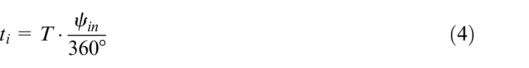
As shown in Figure 4, in a cutting layer, the expressions for the cutting depth ac and the cutting width ae are

where ψ denotes the tooth position angle in degrees and af denotes the feed rate per tooth in mm/z.
Three cutting elements.
The empirical formula for the milling force can be obtained from the power function by linear fitting of the cutting force test data for different cutting depths and feed rates. By applying linear regression and taking the cutting depth and feed rate per tooth as variables, it is possible to solve the milling force index. The empirical formula for the milling force is

Its calculating logarithm is

The linearization of formula (8) is

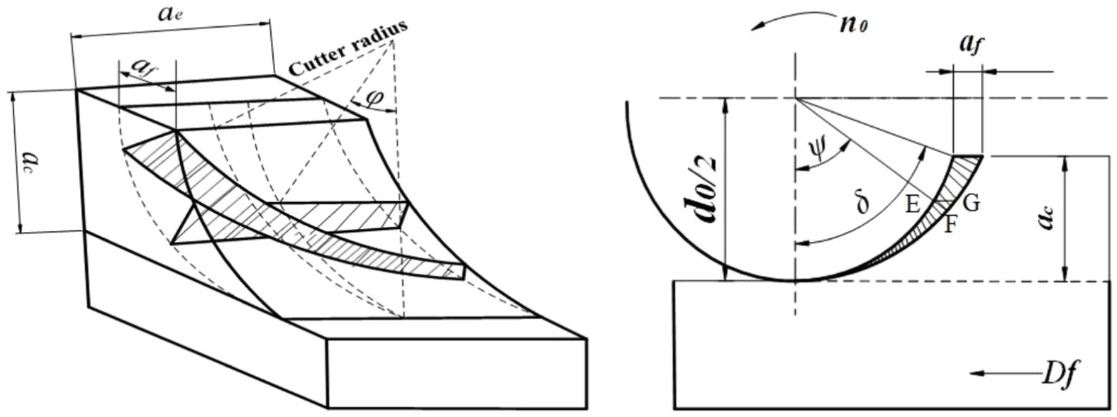
The milling force test data and calculation results are shown in Table 4. With the aid of MATLAB regression processing for the date function and curve fitting function, the coefficients and exponents of the empirical formula were solved. As can be seen from the table, when the cutting depth is constant, the cutting force increases with an increase in the feed rate. When the feed rate is constant, the cutting force increases with an increase in cutting depth.
Test data and calculation results.
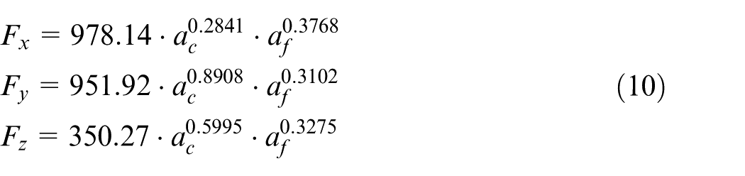
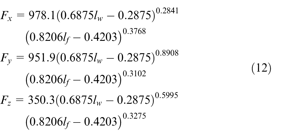
The empirical formulas for the three directions obtained by fitting are
The empirical formula for the contact area between the cutter and the chip
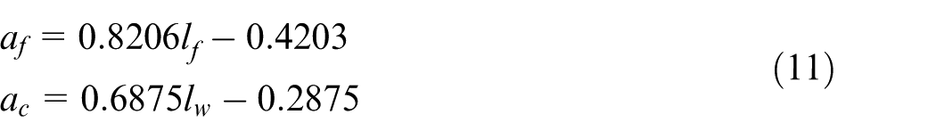
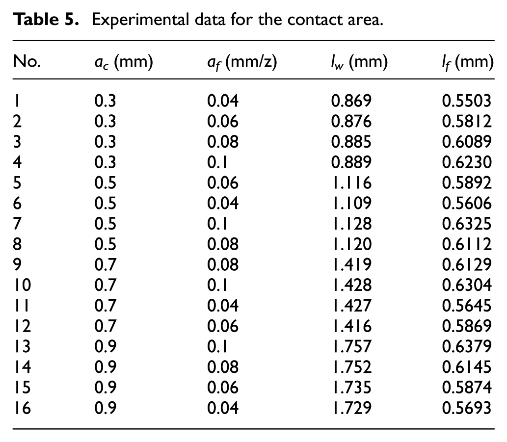
For the area of close contact between the cutter and the chip, if the normal force is a constant, the friction coefficient increases and decreases in tandem with an increase or a decrease in the nominal contact area. The application of a micro-texture can reduce the contact area, thus producing an anti-wear and anti-friction effect. This also affects the milling force. In that case, it is necessary to determine the force density function for milling titanium alloy with a micro-textured ball-end milling cutter by calculating the contact area. The contact area is determined by the contact length and the contact width between the cutter and the chip. The theoretical calculation for this is complex and tedious, so data fitting and data analysis can be carried out using the experimental data instead. The test data are shown in Table 5. The relationship between the contact width, contact length, cutting depth and the feed rate was analyzed using Origin software (see Figure 5). As can be seen from the diagram, the contact width is related to the cutting depth and increases as the cutting depth increases. The contact length is related to the feed rate and increases as the feed rate increases. MATLAB linear fitting was used to obtain the relationship between the contact length lf and the feed rate af, and the contact width lw and the cutting depth ac. These are, respectively
Experimental data for the contact area.
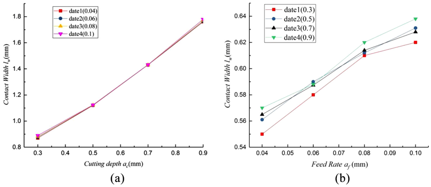
Relationship between (a) the contact width and the cutting depth and (b) the contact length and the feed rate.
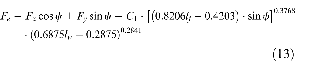
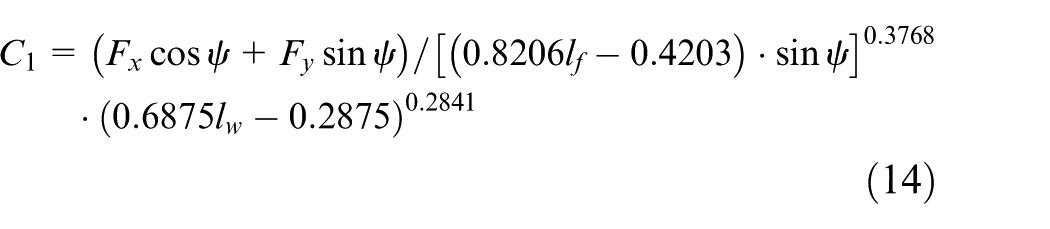
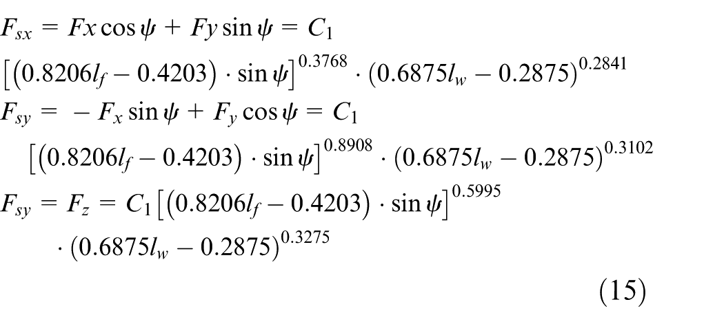
On the basis of formulas (12) and (13), the milling force for milling titanium alloy with a micro-texture ball-end milling cutter can now be obtained
The force density function for the rake face of a micro-textured ball-end milling cutter
The cutting force acting on a micro-textured ball-end milling cutter changes over time and the degree of variation in the milling force affects the magnitude of the stress, thereby affecting the service life of the cutter. The reason for solving the force density function for the rake face of a micro-textured ball-end milling cutter, in that case, is to identify a point that reflects the mutational cutting force. Once this is known, the cutter structure and distribution of the cutting force can be improved. This is not just a matter of solving the average milling force per unit area for the rake face. The characteristics of intermittent cutting mean that the milling force changes periodically over time, so the load boundary condition is not a fixed value, but rather a function of this changing milling force. In that case, the application of load boundary conditions is equal to a function of the solution of the cutting force changing over time, with all of the milling forces being considered in the solution belonging to the same cutting cycle.
The empirical formula for instantaneous milling force is F瞬
According to formula (16), the instantaneous milling force model for the three directions is
On the basis of the milling force test, the functions for changes in milling force over time in the directions of X, Y and Z can now be fitted and then obtained.
Thus, the milling force and the contact area between the cutter and the chip are not linearly proportional to each other. Instead, it is necessary to solve the partial derivative function. The partial derivative function can reflect the instantaneous cutting force and assist in finding the point that represents the instantaneous mutational force. For the derivation of formula (15), the initial force density function for the rake face is
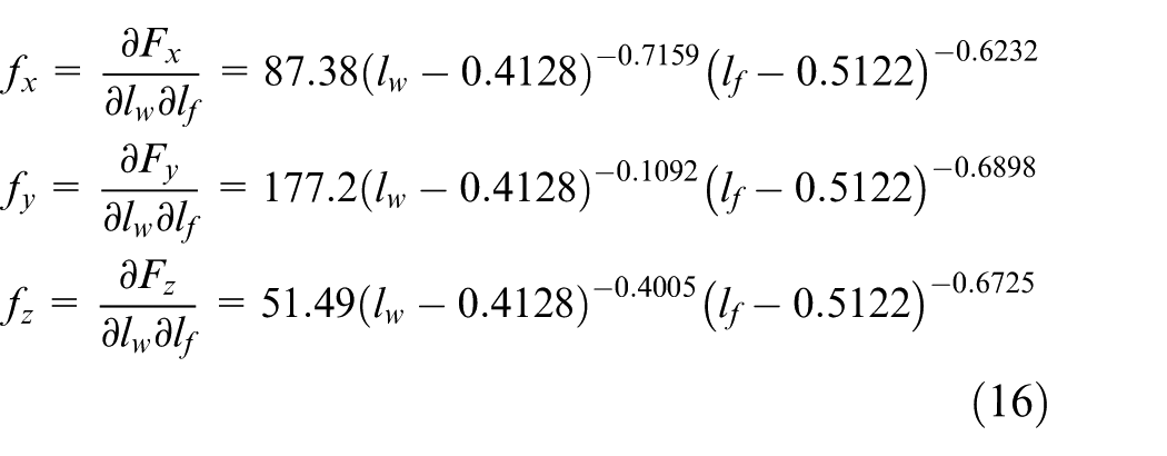
where
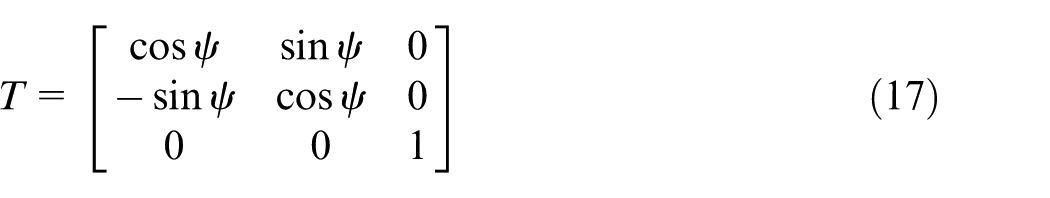
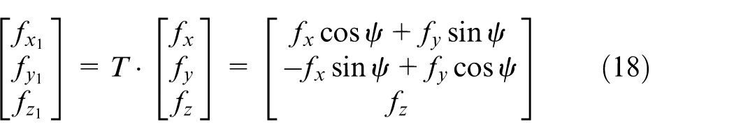
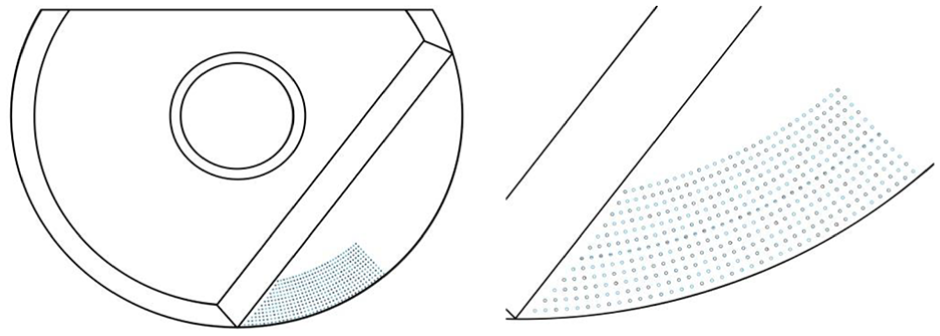
The force density functions in the above equation can be solved using a machine tool coordinate system. Thus, when the micro-textured ball-end milling cutter has rotated for one cycle, the instantaneous force can be found in the cutter coordinate system, as shown in Figure 6. The force density function for the rake face can be obtained by undertaking a coordinate transformation for when the cutter cuts out. The matrix for the transformational relation is
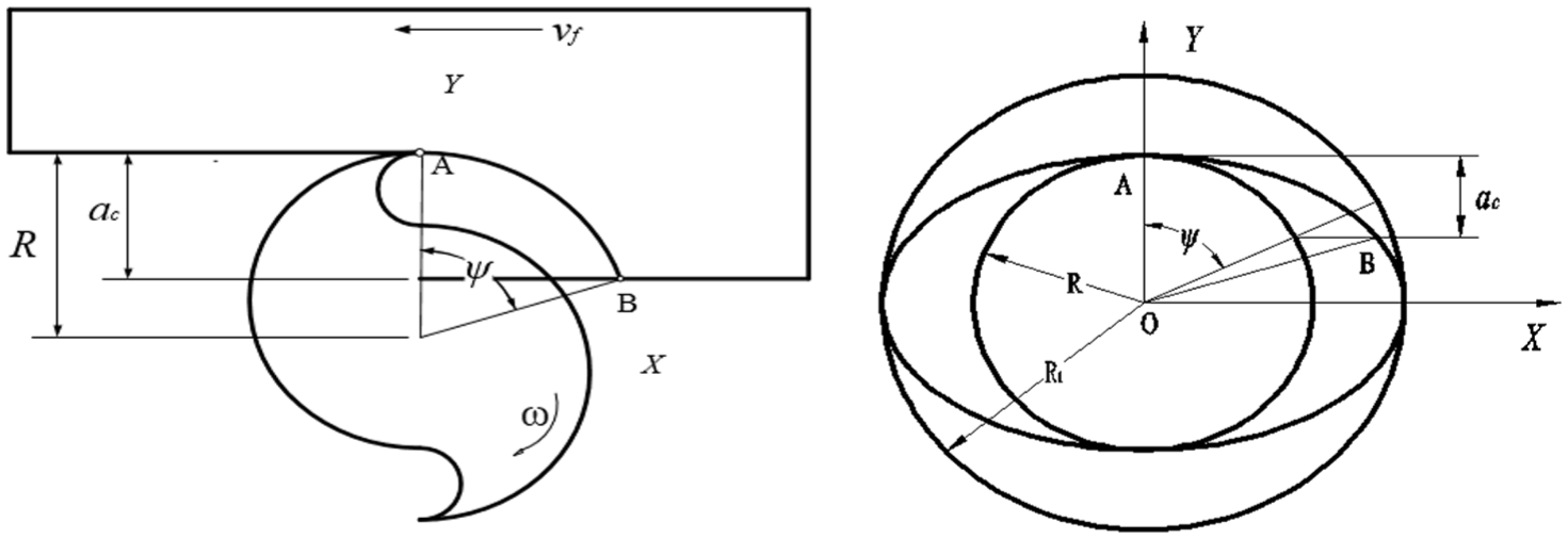
Diagrammatic sketch of the cutting in and cutting out of a ball-end milling cutter.
On the basis of formula (17), the force density function for the rake surface can now be obtained
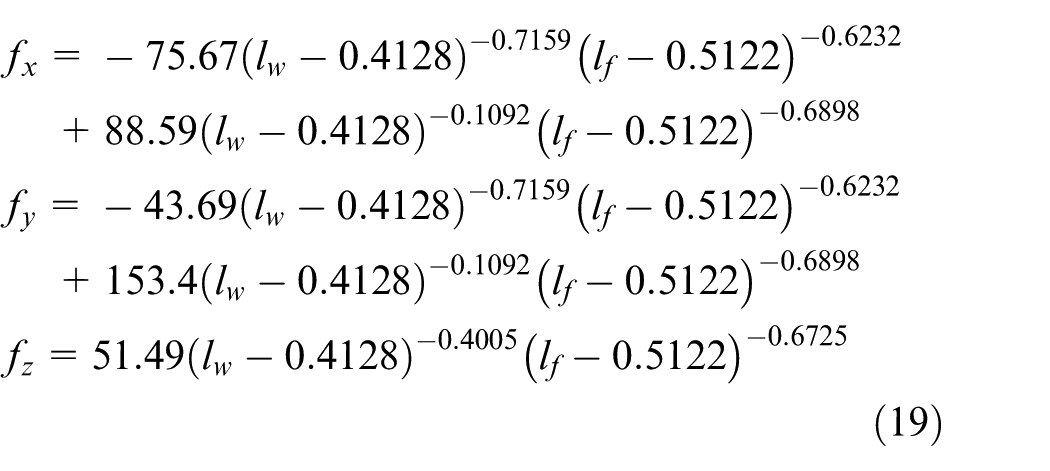
where
According to formula (18), the cutting force acting on the micro-textured ball-end milling cutter varies with any change in the contact area, while the material properties themselves do not change, that being so the force density function of the cutter can be used widely to analyze the cutting force of the same material under different working conditions, thus providing the basis for improving cutter performance.
The force density function was analyzed using MATLAB to observe the cutting force distribution on the cutter’s rake face visually. As shown in Figure 7, the force acting on the rake face is uneven in the two directions of the contact length and the contact width. The cutting force is concentrated in the close contact area between the cutter and the chip, especially around the cutter nose. The closer one is to the cutter nose, the greater the force density function value will be. This indicates that the cutting force near the cutter nose is uneven, so the number of potential mutation points for the cutting force in this region is large. At the same time, it can be seen that the force acting on the rake face in the direction of the contact width is greater than the force acting in the direction of the contact length. It can also be seen that the force acting on the rake face in the direction of the main tool edge is greater than the force acting in the radial direction. So, the obtained force density function is larger than the force per unit area. The main reason for this is that a micro-textured ball-end milling cutter is not a rigid body. When the cutter is in contact with the workpiece, the cutter deforms elastically, making the contact area between the cutter and the workpiece become larger. Thus, the measured value of the milling force will become smaller.
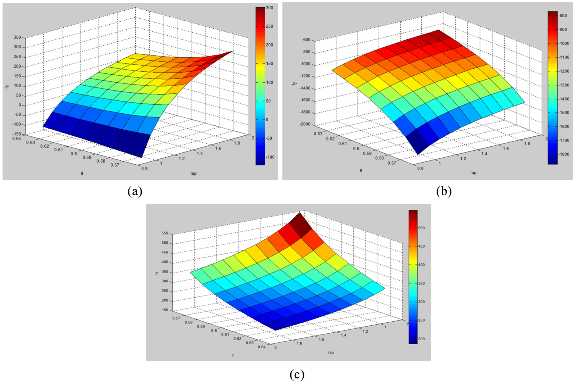
Distribution of the force density function in (a) the X direction, (b) the Y direction and (c) the Z direction.
Simulation analysis of the stress field
Establishing the simulation model
In high-speed milling, failure due to wear is a serious problem. The law of change relating to the milling force determines the degree of tool wear and this affects the surface quality of the workpiece. It is therefore necessary to analyze the force distribution for the cutter. In view of the high cost of conducting experiments, a finite element physical simulation is usually used to simulate the force distribution for tools such as micro-textured ball-end milling cutters. 18 The texture and geometric parameters of the cutter were optimized using a simulation analysis. This can provide the basis for optimizing the cutter structure design and studies of thermo-mechanical coupling behavior. Since the milling force changes over time during the milling process, the stress field in the simulation process is taken to be the instantaneous stress field.
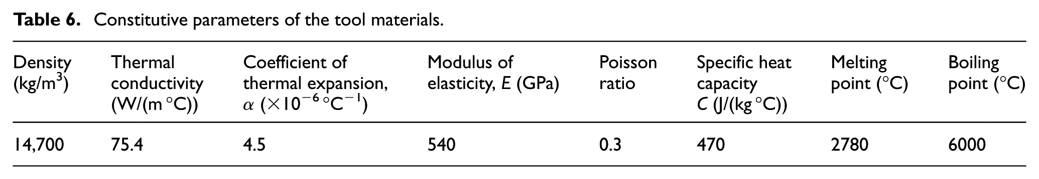
The force distribution for a micro-textured ball-end milling cutter can be simulated using the ANSYS Workbench. At the same time, SolidWorks can be used for modeling. In the process of modeling, calculating the simulation for the whole tool is too large and is time-consuming, so the model needs to be simplified. The location of the micro-texture is the contact area between the cutter and the chip on the rake face, so the simulation was only carried out for the forces relating to the blade. The blade model is shown in Figure 8. The blade in the figure is taken to be indexical of micro-textured ball-end milling cutters more generally. The blade diameter is 20 mm and the micro-texture is etched into the rake face. The shape of the micro-texture is micro-pits with a diameter of 50 μm and a depth of 35 μm. The distance from the micro-pits to the cutting edge is 120 μm and the distance between any two adjacent micro-pits is 120 μm. The material parameters of the cutter are shown in Table 6.
The blade model.
Constitutive parameters of the tool materials.
After modeling, a force distribution simulation of the micro-textured ball-end milling cutter was carried out, following the steps of inputting the model, defining the material attributes, partitioning the meshes, defining the boundary conditions, analysis and solutions, and image analysis. The generation of the meshes is the most important part and the uniformity of the mesh determines whether the force distribution will also be uniform.19,20 By refining the meshes, especially those in the area relating to the distribution of milling force, they can mostly be divided into tetrahedra. Most of them are second-order elements, for which the mesh quality does not need to be very great. The optimized meshes are shown in Figure 9(a). The accuracy and speed of calculation can be affected by simulation with these kinds of meshes, so the meshes need to be optimized.
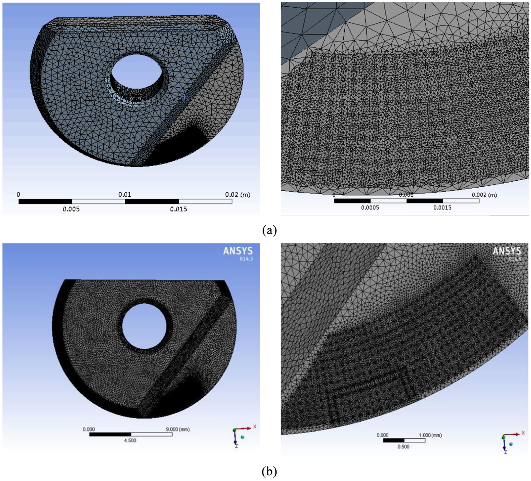
Mesh generation: (a) meshes that are not optimized and (b) optimized mesh.
Mesh optimization is performed using the ICEM CFD module in the ANSYS Workbench. The ICEM module is able to perform computer-aided design (CAD) model restoration, automatic middle surface extraction, unique mesh sculpting and editing. It also offers extensive solver support. There are three kinds of ICEM mesh models: hexahedral mesh, tetrahedral mesh and prismatic mesh. Among these, hexahedral mesh can generate multi-extension block structures and unstructured mesh. Tetrahedral mesh is suitable for fast and efficient meshing of complex models, which is realized through automatic mesh generation. Prismatic mesh is mainly used for mesh refinement at the boundary layer or for the transition between meshes of different shapes. Compared to tetrahedral mesh, it is more regular and can provide better computational regions at the boundaries. In our study, we needed to be able to examine the effect of micro-textures on the force distribution for ball-end milling cutters involved in processing titanium alloy. The magnitude of these micro-textures is very small. As the phenomenon of stress concentration is at its most obvious in the contact area, the meshes here need to be finely divided, so the calculation takes a long time. Optimized tetrahedral meshes need to be used to solve the equivalent stress and equivalent displacement. However, the meshes can be large outside of the contact area, though the transition from the small units to the large units does need to be smooth. After division, the mesh accuracy can be checked and distorted meshes can be modified. An optimized mesh is shown in Figure 9(b). There are fewer optimized mesh nodes, making the calculation more accurate and faster. The force distribution for the simulated micro-textured ball-end milling cutter proved to be very close to that witnessed in actual machining.
Boundary conditions and applied loading
When the meshes are divided evenly, the displacement and load boundary conditions can be set in the loading area. As the blade is fixed to the cutter body, this imposes constraints that limit the movement of the blade in the radial and axial directions. In other words, all of the degrees of freedom for the micro-textured ball-end milling cutter are constrained. As the stress field relating to the milling force is very complex, the application of loading conditions determines the accuracy of the simulation. In that case, the applied boundary conditions need to be simplified to the force of the blade. The farther the cutting force is away from the tool edge, the smaller the milling force will be, with the milling force becoming equivalent to the linear surface loading. Evidently, then, the loading only needs to be applied in the close contact area. The loading boundary conditions were set up according to the above. Then the finite element simulation was solved. Further analysis of the force relating to the milling of titanium alloy with a micro-textured ball-end milling cutter can be conducted at any time. The boundary conditions for the micro-textured ball-end milling cutter are shown in Figure 10.
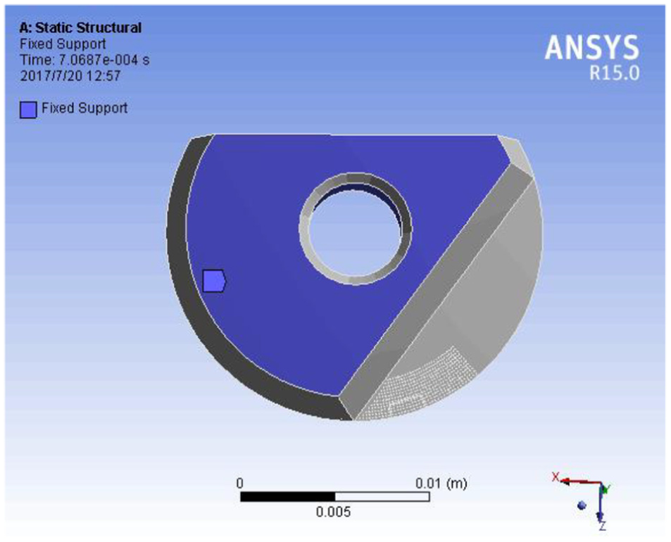
Boundary conditions for the micro-textured ball-end milling cutter.
Analysis of the simulation results
The solution of the finite element simulation provided the equivalent stress and equivalent displacement for the micro-textured ball-end milling cutter. After the boundary conditions had been set up, the simulation calculation was done and the equivalent stress and equivalent displacement were obtained at 0.002 s, as shown in Figure 11. As can be seen from the diagram, the stress concentration was at its most serious at and below the tool edge, with a maximum value of 724.83 N. The stress concentration from the tool nose to the cutter body decreases gradually. The reason for this is that, during the finishing of titanium alloy, the plastic deformation of the workpiece causes the cutter and the workpiece to be extruded into the contact area. This extrusion causes changes in the metallurgical structure of the contact area, which results in stress concentration. This is consistent with the force density function and with the main position of tool wear encountered in actual processing. Alongside this, the stress on the rake face is also large. However, the maximum equivalent displacement occurs at the cutter nose and along the main tool edge, which is the weakest region of the tool in relation to deformation. Thus, it is consistent with the main location of cutter deformation in actual machining processes. Through the simulation analysis of the equivalent stress and displacement, it can be concluded that a more reasonable tool structure would improve cutting performance, reduce tool wear and prolong cutter life.
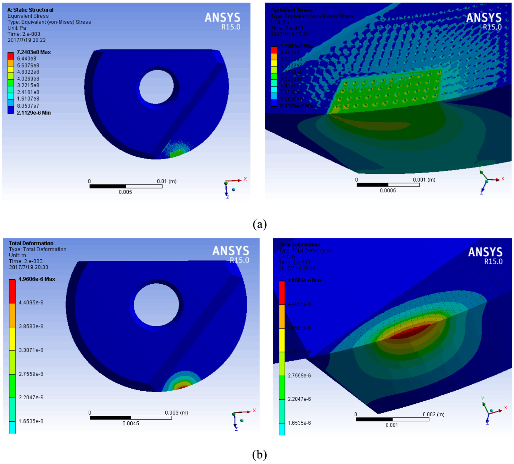
Nephograms of (a) the equivalent stress and (b) the equivalent displacement.
Conclusion
In this article, we have looked at the stress field and distribution of forces generated by the cutting force associated with the machining of titanium alloy with a micro-textured ball-end milling cutter. Based on the initial experimental data, empirical equations modeling the milling force were established by means of fitting with linear regression. At the same time, empirical equations modeling the contact area were also established. The force density function for a machine tool coordinate system was solved using the preceding empirical formulas. After coordinate transformation, the force density function for the coordinate system for the cutting tool was obtained. This provided the basis for studying the stress field generated by a micro-textured ball-end milling cutter.
The equivalent stress and equivalent displacement of the micro-textured ball-end milling cutter were simulated and analyzed, and the instantaneous stress and strain were obtained for any point in time. The simulation results showed that stress concentration was at its most serious at and below the tool edge, with a maximum value of 724.83 N. The stress concentration gradually decreases as one moves from the tool nose to the cutter body. The stress on the rake face is also significant. However, the maximum equivalent displacement occurs at the cutter nose and along the main tool edge, which is the weakest region for tool deformation. The stress obtained after the test was a residual one, which is different from the forces discussed in this article. Here, we have verified the accuracy of the force density function and provided a basis for further study of stress distribution in micro-textured ball-end milling cutters.
Footnotes
Declaration of conflicting interests
The author(s) declared no potential conflicts of interest with respect to the research, authorship and/or publication of this article.
Funding
The author(s) disclosed receipt of the following financial support for the research, authorship, and/or publication of this article: National Natural Science Foundation of China (Grant No. 51875144).