
Abstract
Rotary ultrasonic machining has been widely used for machining of hard and brittle materials due to the advantages of low cutting force, high machining accuracy, and high surface integrity. Focusing on the development of specialized rotary ultrasonic machining systems, this article summarizes the advances in the functional components and key technologies of rotary ultrasonic machining systems for hard and brittle materials, including the ultrasonic generator, power transfer structure, transducer, ultrasonic horn, and cutting tool. Developments on the automatic frequency tracking method, the establishment of an electrical compensation model for power transfer, the energy conversion characteristics of piezoelectric materials and giant magnetostrictive materials, and the design methods for the ultrasonic horn and cutting tool were elaborated. The principle of magnetostrictive energy conversion, output amplitude characteristics of a giant magnetostrictive transducer, and high-power giant magnetostrictive rotary ultrasonic machining systems were also presented. Future research and developments of rotary ultrasonic machining systems regarding the ultrasonic generator, amplitude stability, energy conversion efficiency, vibration mode, and system integration were finally discussed.
Keywords
Introduction
The traditional ultrasonic machining method uses an ultrasonic vibration tool for abrasive hammering, polishing, hydraulic impact, and the resulting cavitation in an abrasive liquid medium, which causes material removal from the workpiece surface. Many companies in the United Kingdom, Germany, the United States, and Japan developed different types of traditional ultrasonic machining tools, and some models have been put into production. 1 However, in traditional ultrasonic machining, the cutting tool with high-frequency vibration has an indirect effect on the workpiece due to suspended abrasive particles; thus, it is difficult to establish an accurate motion model, and the removal rate and machining efficiency of the machined surface cannot be predicted accurately due to the irregular movement of the abrasive particles. 2
In 1964, the British scholar Legge proposed an ultrasonic machining method without abrasive slurry, which combined traditional ultrasonic machining with grinding machining; this method proved efficient and improved the material removal rate over traditional ultrasonic machining, 3 as shown in Figure 1. When the cutting tool for grinding is replaced with a drill, a milling cutter, or other cutting tools, the method is usually referred to as ultrasonic-assisted machining, such as ultrasonic-assisted drilling 4 and ultrasonic-assisted milling. 5

The method developed by Legge: (a) rotating transducer head and (b) tools for various operations. 3
Recently, due to increasing demand for applications of hard and brittle materials, such as optical glass, sapphires, ceramics, and ceramic matrix/reinforced phase composites in aerospace, national defense, military, and electronic information, high-efficiency and low-damage machining methods suitable for these materials have also attracted increasing attention. Practical and experimental studies have shown that rotary ultrasonic machining (RUM) is a suitable method because it has excellent material removal efficiency and good machining quality for hard and brittle materials.
The basic structure of a general rotary ultrasonic machining system (RUMS) is shown in Figure 2. It includes an ultrasonic generator, a power transfer structure, a transducer, an ultrasonic horn, a cutting tool, and other functional components. The ultrasonic frequency signal generated by the ultrasonic generator is transferred to the transducer by the power transfer structure. The transducer may be a piezoelectric transducer or a magnetostrictive transducer depending on the energy conversion materials, and its purpose is to convert electrical energy into mechanical energy.

Schematic diagram of an RUMS.
The ultrasonic vibration is amplified and transmitted through the ultrasonic horn to the cutting tool fixed at the end of the horn. For the general RUMS in Figure 2, the ultrasonic vibrator consists of a transducer, an ultrasonic horn, and a cutting tool. The workpiece is fixed and the ultrasonic vibrator is attached to the tool holder, vibrating around the z-direction while it rotates and is fed to the workpiece. However, from the perspective of kinematics, the rotation of an RUMS refers to the relative rotation between the workpiece and the cutting tool. Therefore, there are many methods to realize the rotation of an RUMS.
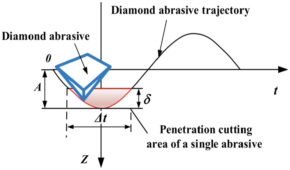
In Figure 2, the trajectory of an abrasive particle in RUM can be defined using equation (1) 6

where

The trajectory of a diamond particle in RUM. 6
The abrasive particle in RUM has an intermittent impact on the workpiece; the schematic diagram of the impact process is shown in Figure 4. The effective contact time

where
The intermittent impact of an abrasive particle in RUM. 7
The machining mechanism in RUM is shown in Figure 5; the average cutting force

where
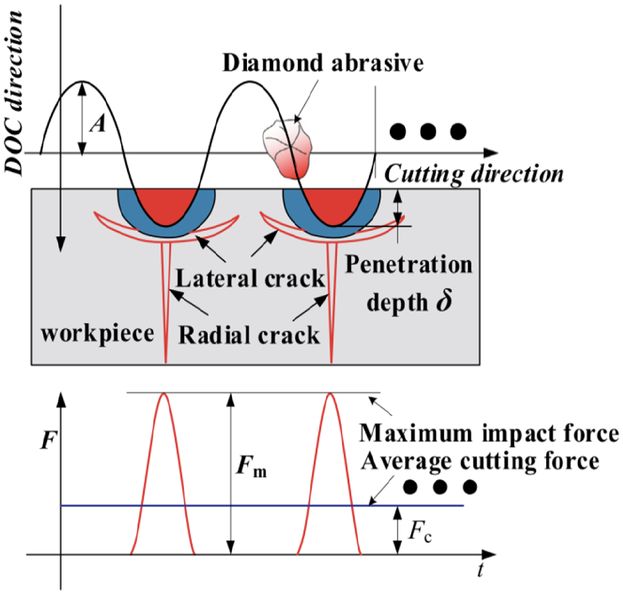
The machining mechanism in RUM. 8
In recent years, many scholars have made significant progress in the development of RUM technology. As RUM technology has matured, the method has not only improved the surface quality of the workpiece, increased the processing accuracy, and prolonged the cutting tool life, 9 but also improved the processing efficiency. Under the same processing conditions, the processing efficiency of RUM can be 10 times that of traditional ultrasonic machining. 10
Functional components and key technologies of RUMSs
Ultrasonic generator and automatic frequency tracking technology
The ultrasonic generator (also known as the ultrasonic power supply) generates and amplifies the alternating current signal, which is utilized to output the required ultrasonic frequency excitation signal to the system. However, the resonance frequency of an RUMS is affected by the mechanical load and temperature, resulting in resonance frequency drift. Therefore, the excitation signal frequency of the ultrasonic generator needs to be determined in real time to match the varying resonant frequency to ensure the correct energy output of the system and maximize the processing efficiency.
At present, the signal generation and power amplification of the ultrasonic generator is relatively mature technology. Many scholars have developed and applied different ultrasonic generators in various fields, such as ultrasonic cleaning, 11 ultrasonic welding,12,13 and processing of hard and brittle materials. 14 As shown in Figure 6, Shen 15 designed an intelligent digital controlled ultrasonic generator. It can set the output power and achieve automatic tracking of resonant frequency.

An intelligent digital controlled ultrasonic generator. 15
Automatic frequency tracking represents the most difficult technical aspect of ultrasonic generators. The most widely used frequency tracking methods include acoustic feedback and electrical feedback methods. The acoustic feedback method acquires the mechanical signals and converts them into electrical signals to create feedback signals for the frequency tracking system; by detecting the frequency corresponding to the maximum amplitude, the resonant frequency is automatically tracked.16,17 However, due to the direct contact between the cutting tool and the workpiece in RUM, it is difficult to measure the ultrasonic amplitude at the end of the cutting tool; therefore, the acoustic feedback method is not feasible for RUM. The electrical feedback method automatically tracks the frequency in the resonant state by acquiring electrical signals from the electrical impedance characteristics of the system. Because of the convenience of acquiring the electrical feedback signal, most scholars have used the electric feedback method to develop automatic frequency tracking methods.
Many methods have been proposed for automatic frequency tracking in piezoelectric systems, including the maximum power method, 18 maximum current method,19,20 and phase-locked loop method.21–23 Ben-Yaakov and Lineykin 24 analyzed the design principle of a power search and tracking method for different loads to achieve frequency tracking. Tangel et al. 11 used a multi-output function to investigate frequency tracking and proposed a frequency tracking algorithm.
Magnetostrictive systems exhibit different impedance characteristics than piezoelectric systems due to different energy conversion modes.25,26 The two types of systems have the following characteristics: (1) circuit characteristics—the piezoelectric system has a capacitive circuit, whereas the magnetostrictive system has an inductive circuit; (2) energy conversion modes—the piezoelectric system converts electrical energy into mechanical energy, whereas the magnetostrictive system converts electrical energy into magnetic energy and then into mechanical energy. Therefore, the frequency tracking method suitable for a piezoelectric system is not applicable to a magnetostrictive system. At present, there is little research on the automatic frequency tracking of magnetostrictive systems. Xu et al.27,28 utilized the magnetostrictive inverse effect to detect the resonance frequency of the system using a driving coil or a detecting coil, which improved the efficiency of the transducer. This method successfully reduced the volume of the transducer, but increased the complexity of the structure; moreover, the detecting coil does not acquire the feedback signal when the transducer is rotating. Therefore, there are very few studies on automatic frequency tracking methods for giant magnetostrictive rotary ultrasonic machining systems (GMRUMSs). Examples of research on automatic frequency tracking methods are listed in Table 1.
Automatic frequency tracking technology for different systems.

Electric power transfer structure and electrical compensation model
Efficient power transfer is the key problem in RUMSs. Ultrasonic power transfer technology can be categorized into contact power transfer mode and non-contact power transfer mode. The traditional power transfer method utilizes carbon brushes and conductive sliding rings to transfer the power. The Sonic-Mill Company (USA) and GFM Company (Austria) have adopted this method to design RUMSs. 1 However, this method is vulnerable to friction and heat generation between the carbon brush and the conductive sliding ring, which causes significant wear and heat and reduces the stability of the power transfer. Therefore, the application of contact power transfer is limited in RUMSs.
In recent years, non-contact power transfer methods based on electromagnetic induction have attracted wide attention. This method is also called loosely coupled inductive power transfer (LCIPT).29,30 An LCIPT system includes a primary coil and a secondary coil, and cores are usually used to ensure the formation of a magnetic circuit. According to the principle of electromagnetic induction, high-frequency alternating current in the primary coil generates a high-frequency alternating magnetic field and an induction electromotive force in the secondary coil to achieve non-contact power transfer.
LCIPT systems have been applied in robotics, radar applications, and induction motors. Many scholars have investigated the design and electrical compensation theory of LCIPT systems.31,32 Four types of structures of rotary LCIPT systems have been proposed, as shown in Figure 7. 33 Gray color represents the cores, the grid pattern represents the primary coil, and the oblique dashed lines represent the secondary coil.

Four types of structures of rotary LCIPT systems: (a) concentric, (b) coaxial winding with pot core, (c) adjacent winding with pot core, and (d) no core. 33
With the development of RUM technology, research has focused on the system requirements of RUMSs using LCIPT with high spindle speed and stability.34–36 The German DMG company took the lead in introducing LCIPT systems into the ultrasonic series of ultrasonic machine tools. Pi et al., 34 Shen et al., 35 and Bortis et al. 36 analyzed the influence of LCIPT technology on RUMSs and conducted experimental research of the influence of the shape, size, and air gap of the LCIPT system on the power transfer efficiency. Ma, 37 Pang, 38 and Huang 39 promoted the application of LCIPT technology in various types of RUMSs and researched ultrasonic honing, rotary ultrasonic grinding, rotary ultrasonic drilling, and similar applications. At present, the theory and structural design of LCIPT technology are well developed in RUMSs. However, due to the electrical impedance characteristics of the transducer in the resonant state and the leakage inductance of the loosely coupled transformer, it is necessary to conduct additional studies on matching the electrical compensation.
The LCIPT system produces inductance as a result of the ultrasonic excitation, which limits the ultrasonic power transfer. In addition, the electrical and acoustic matching of the transducers also has a large influence on the amplitude characteristics. Therefore, it is necessary to compensate for the impedance in the LCIPT system to improve the overall performance of the RUMSs using impedance matching, tuning, and shape filtering.
Numerous studies have been conducted on electrical compensation models for piezoelectric systems. Electrical compensation has four types of topology, namely, series–series, series–parallel, parallel–parallel, and parallel–series. Zhu et al. established a parameter compensation model to maximize the power transfer efficiency and analyzed the influence of the load on the power transfer efficiency of the LCIPT system. The results showed that the series–series compensation topology was most suitable for the maximum load fluctuation. 33 Shen et al. 35 developed a mutual inductance model for an LCIPT system and examined the equivalent circuit of the piezoelectric oscillator, as shown in Figure 8. The results showed that the relative rotation of the primary and secondary structures affected the fluctuation of the mutual inductance coefficient, causing the accuracy of the electrical compensation circuit to decline; a compensation method that was independent of the mutual inductance coefficient was proposed.

The mutual inductance model of an LCIPT system. 35
In Figure 8, M is the mutual inductance between the primary circuit and the secondary circuit;

where
Eight different types of primary and secondary compensation for a piezoelectric ultrasonic system were analyzed to ensure that the maximum amplitude was reached. 15 The results are shown in Table 2. “Capacitance” and “inductance” in the table indicate the type of compensation element used when the maximum amplitude output condition is satisfied. “Invalid” means that the compensation type cannot output the maximum amplitude. “Not applicable” means that the primary compensation element is not applicable to the compensation type.
Comparison of primary and secondary edge compensation methods. 15

Cai et al. 40 researched series–series electrical compensation for magnetostrictive systems. The results showed that the optimal compensation parameters in this mode improved the amplitude characteristics of the RUMSs. Most studies on electrical compensation models have focused on single LCIPT or piezoelectric systems. Further research on electrical compensation models is needed for magnetostrictive systems.
Transducer
The transducer is a key component in RUMSs. It converts high-frequency alternating signals into mechanical vibration. Its development is closely related to the development of the preparation methods for energy conversion materials. Transducer materials are categorized as electrostrictive materials and magnetostrictive materials, 41 and similarly transducers are either electrostrictive or magnetostrictive.
In 1910, the French scholar Langevin successfully developed the first generation of the sandwich-type ultrasonic transducer using the quartz crystal material with electrostrictive properties. In the 1950s, piezoelectric ceramics consisting of lead zirconate titanate (PZT) and lead magnesium niobate (PMN) 42 were developed successively in the United States and Japan, resulting in a significant increase in research on piezoelectric transducers. Piezoelectric transducers are widely used in practical production because of their simple structure, low cost, and good energy conversion performance; piezoelectric transducers are commonly used in existing RUMSs.
In the 1970s, Dr Clark in the United States first proposed rare-earth compounds with giant magnetostrictive properties; this was followed by the development of giant magnetostrictive transducers. 43 The emergence of novel magnetostrictive materials, which are called giant magnetostrictive materials, led to considerable research activity on giant magnetostrictive transducers. The most commonly used giant magnetostrictive material is the pseudobinary intermetallic compound Tb0.27Dy0.73Fe2 alloy, which is called Terfenol-D.
The performance parameters of PZT and Terfenol-D are compared as shown in Table 3. Terfenol-D shows better performance than PZT;44,45 specifically in terms of the following: (1) the saturation strain exceeds 1500 × 10−6, which is several times higher than that of ordinary PZT, which ensures high power and large amplitude output; (2) the energy density is higher, allowing for miniaturization; (3) the mechanical quality factor and half-power frequency are lower at the same resonant frequency of the two transducers. The amplitude attenuation is lower in the same frequency range due to the larger bandwidth, that is, the amplitude stability is higher; (4) the heat conductivity is higher, providing better heat dissipation; (5) the Curie temperature is higher, and the magnetostrictive characteristics caused by high temperature are reversible. However, due to the high cost and complex structure of giant magnetostrictive transducers, no mass production has been achieved to date. Nevertheless, it is very likely that GMRUMSs will be developed in the future and will possess high power and stability.
Performance parameters of two types of energy conversion materials. 44

PZT: lead zirconate titanate.
In the 1990s, Shamoto and Moriwaki 46 from Japan Nagoya University proposed an elliptical vibration cutting technology to use ultra-precision machining for hard and brittle materials. Elliptical vibration can be achieved by double excitation, multi-mode superposition, and mode conversion. Double excitation requires two transducers to excite the output; this structure is quite complex. In multi-mode superposition, elliptical vibration is achieved by two different excitation modes of one transducer. Obtaining the same resonant frequency for the two different modes represents a problem of this approach. In mode conversion, a unique ultrasonic horn structure is required. Because the three basic vibration modes of the system are longitudinal vibration, torsional vibration, and bending vibration, combinations of these vibration types occur in the elliptical vibration cutting method (e.g. longitudinal–torsional vibration and longitudinal–bending vibration).
Due to the characteristics of piezoelectric materials, which produce changes in the polarization direction in an electric field (i.e. the piezoelectric effect), including axial polarization and tangential polarization (Figure 9), piezoelectric transducers are used to achieve longitudinal–torsional vibration, 47 bending–bending vibration,48,49 longitudinal–bending vibration, torsional–bending vibration, 50 and so on. For axial polarization, PZT produces strain along the axial direction under the action of electric field while along the tangential direction for tangential polarization.

Two polarization directions of piezoelectric materials.
Torsional vibration in magnetostrictive transducers occurs as a result of the characteristics of the magnetic material, which twists in the helical magnetic field (i.e. the Wiedemann effect). However, giant magnetostrictive materials cannot withstand tangential stress caused by the torsional vibration due to the brittleness of the material. FeGa alloy is a magnetostrictive material that was developed in 2000; it has excellent machinability and a high magnetostrictive coefficient. It is an ideal material for a magnetostrictive torsional vibration transducer. 51 However, the use of the FeGa alloy in transducers has not been thoroughly researched, and the material performance remains unclear. Also, few studies were conducted on the composite vibration mode of magnetostrictive transducers due to the complexity of other vibration modes such as torsional vibration. 52
Ultrasonic horn and cutter
The ultrasonic horn is a crucial component of RUMSs; it amplifies the amplitude of ultrasonic vibrations originating from the transducer, transmits the ultrasonic energy, and matches the system impedance. 53 The design objectives for the ultrasonic horn are (1) to ensure that the resonant frequency is close to the theoretical value, (2) to minimize the energy loss, (3) to increase the amplitude amplification factor, and (4) to decrease the maximum equivalent stress. Different design methods and different horn structures are listed in Table 4.
Various design methods for different ultrasonic horn structures.
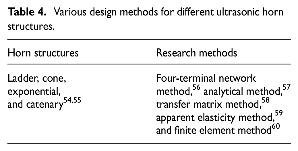
The four-terminal network method and the analytical method are limited to the design of the horn structure, and it is difficult to establish an accurate analytical model for complex structures due to the simplification of the model; the transfer matrix method is only suitable for structures with simple vibration modes, but not for structures with complex motions such as longitudinal torsion and bending. The apparent elasticity method was first proposed to analyze the transverse vibration characteristics of large-scale structures experiencing vibration. When the transverse linearity of this type of structure is less than one-fourth of the wavelength, the transverse effect can be neglected; therefore, the one-dimensional design theory can be used to analyze the transverse vibration characteristics of these types of structures. 59
Because of the advantages of simple parameter setting, wide applicability, and the model equivalence effect, the finite element method (FEM) has become a mainstream method for the design of ultrasonic horns.61–63 Zhang et al. 61 analyzed a composite horn with several cutting tools using the FEM and investigated the influence of the cutting tool structure on the amplification coefficient of the horn. Amin et al. 62 improved the material removal rate using the FEM analysis of the shape of the horn. Rani and Rudramoorthy 63 conducted FEM analysis on various shapes of ultrasonic horns to determine the dynamic performance of the horns.
When RUM is used for hard and brittle materials, diamond abrasives are bonded to the cutting tool using surface electroplating, brazing, or sintering. The interfaces between the cutting tool, ultrasonic horn, and transducer should be considered to improve the energy conversion efficiency of ultrasonic vibration, increase the amplitude of ultrasonic vibration, and ensure rotational accuracy of the system. Zhao et al. 64 examined the influence of cutting tools with an integrated design on the nodal position of the horn. Cong et al. 65 investigated the influence of the structural parameters of the cutting tool on the output amplitude. Dai et al. 66 compared the influences of different horn–transducer connections on the power transfer structure.
In elliptical vibration cutting, a change from longitudinal vibration to longitudinal–torsional vibration of the transducer is achieved by incorporating inclined grooves, inclined beams, and spiral grooves on the horn. This machining method has been successfully applied to optical quartz glass 67 and C/SiC ceramic matrix composites. 68 Since the ultrasonic horn is connected to the cutting tool, which contacts the workpiece in RUMSs, the optimization of the ultrasonic horn structure is crucial to achieving optimal vibration performance.
High-power GMRUMSs
Principle of magnetostrictive energy conversion
The most recently developed structure of a magnetostrictive transducer is shown in Figure 10. The transducer consists of a prestress block, an ultrasonic oscillator, a prestress mechanism, a horn, and other components. 69 The prestress block and prestress mechanism exert a force on the magnetostrictive material. The alternating ultrasonic frequency signal excites the ultrasonic oscillator to produce an alternating magnetic field, which results in the strain of the magnetostrictive material in the axial direction. The horn transmits and amplifies the ultrasonic vibration.
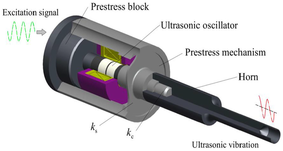
Common structure of magnetostrictive transducers. 69
Characteristics of GMRUMSs
The Terfenol-D material has broad application prospects in ocean exploration, vibration reduction and vibration prevention, micro-displacement drive, automation technology, and fuel injection technology; the material has been successfully used in transducers, valves, and pumps. 70 The giant magnetostrictive transducer developed by the ETREMA Company (USA) achieves frequency regulation in the 20 kHz direct current (DC) range and provides a maximum amplitude output of 10 μm, and air cooling is used to control the temperature of the transducer. Many universities have conducted research on the structural design and vibration characteristics of giant magnetostrictive transducers, such as Tsinghua University, 71 Shaanxi Normal University, 72 Zhejiang University, 73 South China University of Technology, 74 and Xiangtan University. 75 Zeng 76 at the South China University of Technology has developed a prototype of a water-cooled giant magnetostrictive transducer with 20 kHz resonant frequency and an ultrasonic amplitude of about 5.7 μm. However, to date, there are relatively few studies on production-grade giant magnetostrictive transducers.
The factors affecting the amplitude characteristics of a giant magnetostrictive transducer include the excitation signal, 77 bias magnetic field, 78 preload force, 79 and structure of the vibration components, 80 as shown in Figure 11. The bias magnetic field and preload force have the large influence. Numerous studies have shown that the performance parameters of the Terfenol-D material, including the elastic modulus and piezomagnetic coefficient, are related to the bias magnetic field intensity and the preload force. The preload force can increase the saturation magnetostriction coefficient and increase the strain under the same excitation magnetic field.78,81 The material characteristics of the magnetic conductor in the magnetic circuit also have a large influence on the amplitude output characteristics. 82 Galloway et al. 83 and Zheng and Liu 84 proposed the non-linear constitutive model of the Terfenol-D material. Theoretical prediction of the magnetostrictive curves under multi-group prestress conditions was performed, and the validity of the theoretical model was verified by experiments; subsequently, a method was developed to determine the optimal value of the bias magnetic field intensity.85,86

Recent research has mainly focused on the influence of the bias magnetic field and prestress on the magnetostrictive properties of the Terfenol-D material. Giant magnetostrictive transducers that do not rotate are commonly investigated; however, the use of Terfenol-D in RUMSs requires further study.
Terfenol-D has excellent energy conversion characteristics. GMRUMS is a recently developed technology and has the advantages of high stability, high power, large amplitude output, and the ability to be miniaturized. Therefore, it will become an important direction for the future development of RUMSs.
Tsinghua University has developed a novel type of GMRUMSs, called the THU ULTRASONIC 850 (Figure 12). The ultrasonic frequency range is 18–30 kHz, the ultrasonic power is 200–400 W, and the amplitude range of the ultrasonic system is 8–27 μm. The LCIPT system is located between the tool holder and the spindle of the machine tool and is cooled by central air cooling and external liquid cooling. Further studies on automatic frequency tracking technology and ultrasonic generators suitable for the GMRUMSs are required to ensure continuous and stable operation of the system.

The GMRUMS developed by Tsinghua University.
Future research on RUMSs
Based on the current research status of RUMSs, the following topics would be focused on:
Large ultrasonic power. Research has shown that a large ultrasonic amplitude results in lower cutting force, better processing efficiency, and less cutting tool wear during material processing. Therefore, an RUMS with large ultrasonic power and large amplitude output is an important research and development direction. A key topic is the use of energy conversion materials with a high power density. Although some progress has been made in research on giant magnetostrictive transducers, many problems have to be addressed because Terfenol-D is very sensitive to the temperature and preload force.
Output amplitude stability. High temperatures and a large load are the main factors affecting the resonant frequency and amplitude stability of RUMSs. During machining, the thermal–mechanical load, the excitation level, and other factors are coupled and changes occur rapidly. Therefore, it is necessary to establish an effective cooling system. In addition, it is necessary to develop an ultrasonic generator with automatic frequency tracking of the resonance frequency to improve the stability of the system. Since a small mechanical quality factor of the ultrasonic system results in higher amplitude stability, additional research is required to determine the relationship between the amplitude size, the amplitude stability, and the mechanical quality factor.
Energy conversion efficiency. There are three factors that affect the efficiency of RUMSs. The first one is the power transfer structure. Its type, magnetic core material, the winding method, and the air gap between the primary coil and the secondary coil affect the power transfer efficiency. The second factor is the energy conversion mode, including conversion from electrical energy to mechanical energy and from electrical energy to magnetic energy to mechanical energy. The third factor is the combination of the characteristics of the transducer, ultrasonic horn, and cutting tool, whose connection position, connection type, and preload force influence the mechanical energy transfer efficiency. Therefore, it is necessary to conduct studies on the theory, design, and methods to improve the power transfer and energy conversion efficiency of the system.
Multiple vibration mode. The main modes of ultrasonic vibration are longitudinal vibration, torsional vibration, radial vibration, bending vibration, and composite vibration. At present, most of the vibration forms of an RUMS are longitudinal. Different vibration modes are required for different processes. For example, research has shown that a low cutting force is required, and the processing efficiency is higher when longitudinal–torsional vibration rather than longitudinal vibration is used for creating threaded holes and cutting honeycomb materials with a disk cutter. Therefore, it is crucial to investigate different modes of ultrasonic vibration, especially the combination of longitudinal–torsional and longitudinal–bending vibrations in RUMSs.
System integration. Integration in an ultrasonic system refers to the design of the overall structure of the ultrasonic tool holder, the integration of the ultrasonic tool holder and the spindle of the machine tool, the standardization of the connection interface of the cutting tool, as well as the integration of the ultrasonic control system and the numerical control system. Miniaturization of the ultrasonic oscillator will reduce the weight of the RUMS and ensure the integration with the manipulator and parallel mechanisms. The structural design of the LCIPT system also requires further development, such as the ability to change tools rapidly, the compatibility of various types of ultrasonic tools, and an adaptive integrated control method for the process parameters under critical cutting conditions.
Conclusion
Advances in RUMSs for hard and brittle materials were reviewed in this article, and current research and development problems and future directions of RUMSs were investigated. The following conclusions were drawn:
RUMSs need to ensure not only good machining quality, but also the continuity of effective machining. Automatic frequency tracking technology is a key technology in RUM in practical applications, and further research is required, especially for giant magnetostrictive ultrasonic transducers. Moreover, the relationship between automatic frequency tracking technology and ultrasonic power transfer technology should be investigated.
The development of RUMSs should focus on achieving composite vibration modes (longitudinal vibration, torsional vibration, and bending vibration). The piezoelectric transducer is well suited for elliptical vibration. In the research of high-power and multi-mode vibration, the power output and vibration modes of RUMSs using giant magnetostrictive materials require further study due to the material characteristics and structural complexity.
Giant magnetostrictive materials have the advantages of high stability, high power, and large amplitude output due to their superior energy transfer characteristics. Therefore, GMRUMSs would become an important direction of the future development of RUMSs, and an important research direction for the future development of RUMSs is the miniaturization of the components.
Footnotes
Handling Editor: James Baldwin
Declaration of conflicting interests
The author(s) declared no potential conflicts of interest with respect to the research, authorship, and/or publication of this article.
Funding
The author(s) disclosed receipt of the following financial support for the research, authorship, and/or publication of this article: The authors gratefully acknowledge the financial support for this research provided by the National Natural Science Foundation of China (Grant Nos 51875311 and 51761145103) and Shenzhen Foundational Research Project (Subject Layout) (Grant No. JCYJ20160428181916222).