
Abstract
Ultrasonic cold forging technology is a mechanical process used to improve surface characteristics of materials by continual striking of the tool in a reciprocating motion. In this study, the proper geometrical shapes of the booster and the horn (collectively called “the concentrator”) were obtained through numerous simulations based on the frequencies produced, the power of an ultrasonic generator (about 20 kHz), and the mechanical vibrations transferred parallel to the axis of the ultrasonic head (transducer, booster, horn, and tool). Furthermore, a pneumatic system was designed using a simulated ultrasonic cold forging technology in order to supply the static load and to prevent tool backlash in the retracting motion. Post-ultrasonic cold forging technology mechanical tests revealed an improved hardness by 17% to a depth of 150 μm and an enhanced smoothness from an initial value of 0.6–0.132 μm in the compressed layers of the surface as a result of using the ultrasonic cold forging technology process.
Keywords
Introduction
A number of techniques are widely used effectively to improve the mechanical properties of materials through morphological changes in their micro-structural characteristics. Cherif et al. 1 used a technique named ultrasonic nanocrystal surface modification (UNSM) on austenitic steel AISI 304 to show the high compressive residual stresses and remarkable strain hardening after the process. Ting et al. 2 used ultrasonic surface rolling processing (USRP) to enhance the surface hardness of 40Cr by affecting the nano-structured layers at a depth of about 1.4 mm. They also showed that this process was able to reduce surface roughness. Moreover, modern experimental processes such as severe plastic deformation (SPD) have been introduced to achieve finer grains in materials that, compared to conventional forming methods, lead to more plastic deformations. 3 The grain refining mechanism during SPD is similar in certain respects to that of mechanical alloying which includes micro-structural developments such as high-density dislocations, new cell structures, secondary grain boundaries, and secondary boundaries converted to wide-angle boundaries. 4 If this SPD takes place a number of times, the primary grains will repeatedly divide into smaller parts to produce a finer grain structure in the material.
The main advantage of SPD methods over mechanical alloying is that the final product will not need to be subjected to such subsequent processes as compression or sintering. Figure 1 shows a number of the SPD methods developed and used for bulky deformations in materials. More recently, many severe surface plastic deformation (S2PD) processes have been developed that create severe deformations in the surface layers of materials. The results show that S2PD processes improve surface mechanical properties such as hardness, fatigue strength, and smoothness. Also, according to the Hall–Petch theory, S2PD processes lead to a concomitant improvement in hardness and toughness of the material due to grain refinement at certain depths. Pyoun et al. 5 employed one such S2PD process, that is, UNSM, to improve the smoothness and hardness of D2 steel trimming knives and showed an increase of 60%−170% in their service life as a result of the treatment. Interestingly, Cao et al. 6 reported that UNSM was able to increase the fatigue strength and retard the initiation of fatigue cracks in medium strength and tempered steel (S45C). Hukki and Va Laakso 7 used a state-of-the-art technology, namely, the ultrasonic burnishing on 34CrNiMo6-M tempering steel and improved the surface roughness and residual stresses in the workpiece by about 90% and 400%, respectively. In addition, Bozdana et al. 8 used the ultrasonic deep cold process to enhance the service life and the surface properties of Ti6Al4V components.
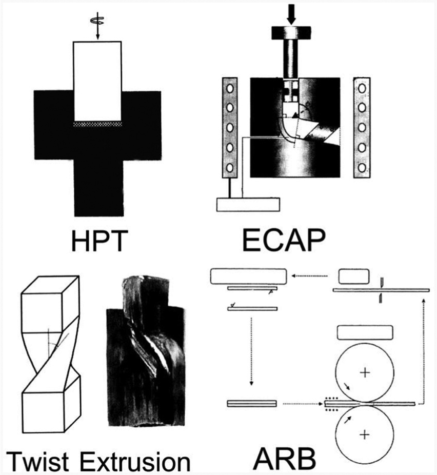
Schematic view of some of the SPD methods so far developed.
Ultrasonic cold forging technology (UCFT) is a modern technique for creating great strain on the surface layers of materials. In fact, the ultrasonic equipment transmits the mechanical energy as a form of concentrated mechanical vibration to the surface layers of the workpiece, whereby the monotonous vibrations increase the hardness and surface smoothness of the workpiece. Interestingly, UCFT can be used as a low-energy replacement for surface heat treatment of rods. 4 In their experiments with hot-worked tool steel (SKD61), Sue et al. 9 showed that UCFT was able to double the compressive residual stresses to a depth of 150 μm, while the fatigue strength and the life of the workpiece were enhanced with a reduced friction coefficient. The advantages and characteristics of the UCFT process may be summarized as follows:
This process can be properly used in steel industries for surface hardening of the rollers and mixtures. 1
It is a modern process with low-energy consumption.
It is a useful process that can be applied to different kinds of materials with different workpiece diameters and lengths.
It is an easy and fast process.
It yields workpiece improved mechanical properties and enhanced physical and micro-structural characteristics. 5
Figure 2 shows a complete set of the UCFT equipment in which a transducer converts electrical into mechanical energy. In this mechanism, electrical energy with frequencies of about 20 kHz (f ≥ 20 kHz) enters the transducer to be converted into mechanical vibrations in the form of reciprocating motions of about 20,000 times per second with a very low amplitude. The function of the booster firmly connected to the transducer is to concentrate and transfer the vibrations to the horn, which increases and reinforces the vibrations transferred from the booster and transmits them to the tool. The booster and horn indeed act together as a concentrator. Eventually, the tool transmits the concentrated vibrations to the workpiece.
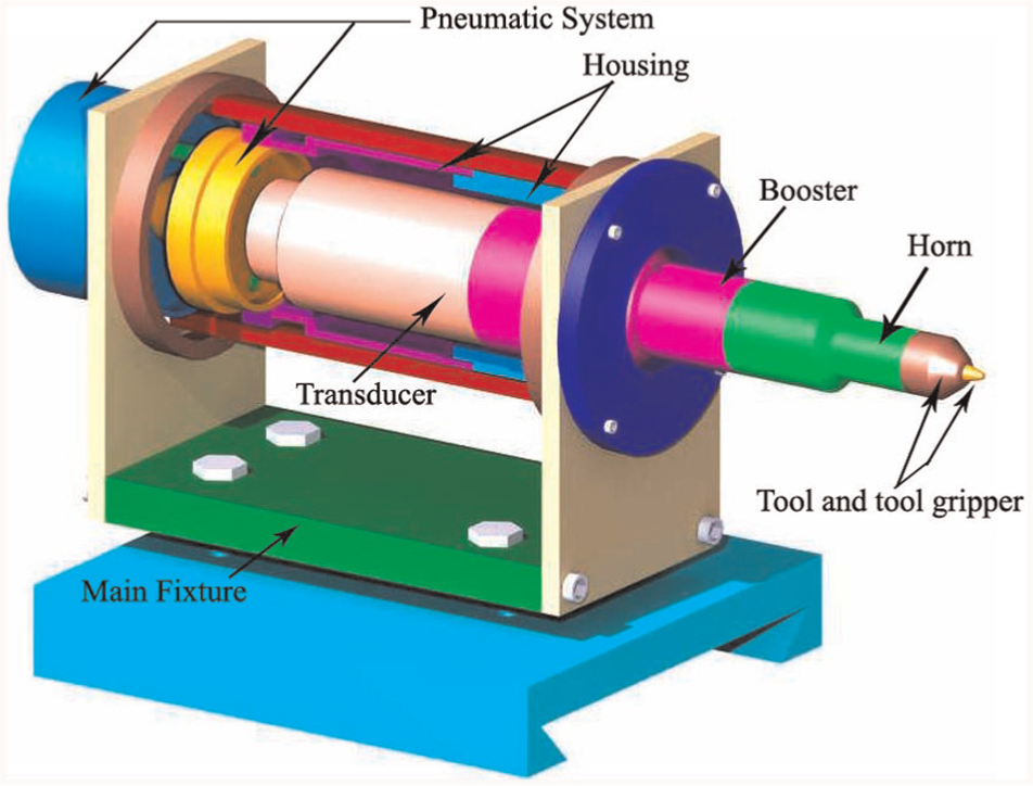
Complete set of the UCFT equipment.
For the purposes of this study, a pneumatic system was used to supply the adjustable static force behind the ultrasonic system that contributes to regular motions of the tool and, as a result, prevents tool backlash. All the components of this experimental setup were designed and manufactured with great precision, and simulations were performed to obtain the proper geometric shapes for the booster and the horn. The ABAQUS software was also used to perform simulations in order to investigate the reaction forces and the effect of the UCFT process on workpiece surface smoothness.
Simulation and design
To manufacture the ultrasonic system, a total of 25 mechanical, pneumatic, and electrical components were used, some of which were produced following a frequency analysis. Figure 3 shows the complete set of UCFT equipment assembled on the lathe. The workpiece, or the rod, turns around its axis on the lathe, and the ultrasonic head (consisting of the transducer, the booster, the horn, and the tool) transmits mechanical vibrations to the workpiece. In fact, the tool continually strikes the workpiece with a frequency of about 20,000 times per second. An ultrasonic generator is used to supply the required electrical energy with a frequency of about 20 kHz and a power of 2.2 kW. Also, a piezoelectric device, named lead zirconate titanate (PZT), is used to convert the electrical energy with a frequency of 20 kHz into mechanical vibrations, that is, a reciprocating motion of 20,000 times per second with a very low amplitude. Thus, it is important to transmit the mechanical vibrations to the tool in only one direction (parallel to the axis of the tool and the booster) at a frequency of 20 kHz. A crucial consideration is the design of the booster and the horn since all the mechanical vibrations must pass through these two components that act as bridges, reinforcing the amplitude of the mechanical vibrations. A complete description of the simulation, design, and manufacturing of the horn and booster is given in section “Design and simulation of the booster and the horn.”
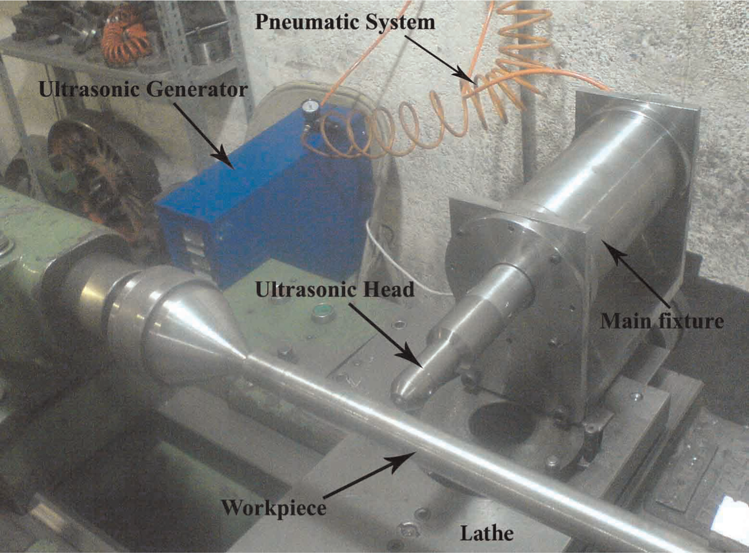
Assembling UCFT equipment on the lathe.
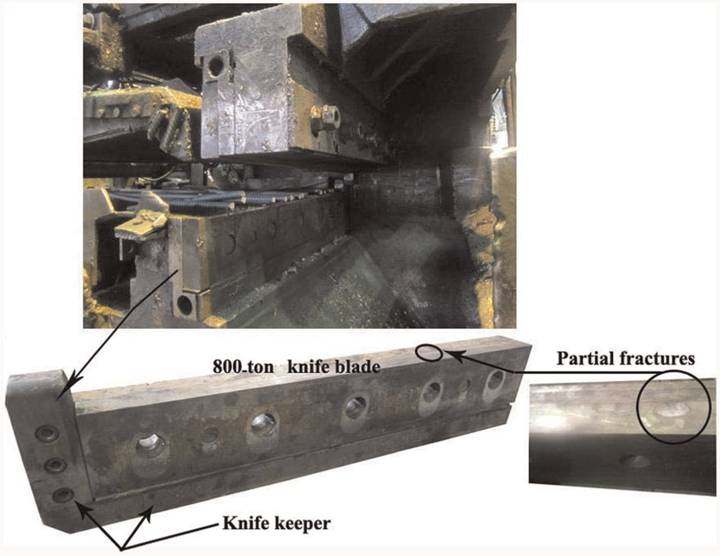
The tool needs to be made from a hard material to have enough strength to resist the high temperature produced during the UCFT process and the distortion and erosion due to the mechanical work. Thus, tungsten carbide was selected in this study for manufacturing the tool with a spherical head and a hardness of 78.9 HRC, and the diameter of the ball head was ground to 4 mm. In addition, a ball gripper was manufactured for holding the tool on the horn. Figure 4 shows the ultrasonic head assembled. Suh et al. 10 claimed that a physical vapor deposition (PVD) coating (i.e. AlCrN) used with the UNSM process would improve the efficiency of high-speed steel 55 tool and its life.

Assembled ultrasonic head.
As already mentioned, a pneumatic system providing the static force behind the ultrasonic head was included in the setup used for this experiment. In fact, when the tool strikes the workpiece, it will probably have an irregular motion on return. The static force provisioned is then used to produce a monotonous reciprocating motion for the ultrasonic head by preventing this irregularity in motion. The designed pneumatic system consisted of a cylinder, a piston, a hose, an air compressor, fittings, a seal ring, and a relief valve with a manometer. The exact piston diameter was determined by simulation using ABAQUS. A description of the simulation process is presented in section “Simulation of the UCFT process and design of a pneumatic system.”
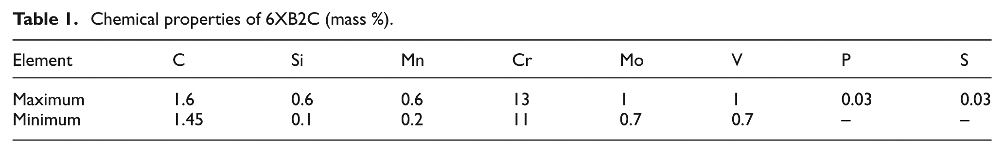
The experiments were performed on the 6XB2C cold-worked alloy steel with the chemical and mechanical properties presented in Tables 1 and 2, respectively. The cold-worked alloy steel used here has a high resistance against impact forces, pressure, and abrasion and is commonly used in the manufacture of such cutting and forming tools as the guillotine blade or the drawing punch. Moreover, the steel has been used for manufacturing an 800-ton knife blade of ESCO with a hardness of 50 HRC that is used for cutting rods. Previous studies have shown broken edges and partial fractures on the surface of the knife blade due to uncontrolled heat treatment and variations in the micro-structural properties during quenching the steel in oil (Figure 5).
Chemical properties of 6XB2C (mass %).
Mechanical properties of 6XB2C.
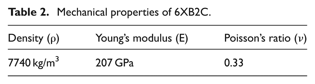
Partial fractures on the surface of an 800-ton knife blade.
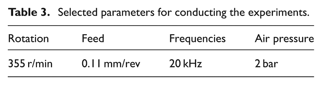
The UCFT process was designed and used in this study to improve the surface mechanical properties of the 6XB2C alloy steel. The application of the UCFT process led to enhanced surface hardness and smoothness of the specimens as evidenced by the results obtained from the mechanical tests performed. A fixture was also designed for holding the ultrasonic head and the pneumatic system on the lathe (Figure 6). Table 3 shows the selected parameters for performing the experiments on the lathe.
The main fixture used for the UCFT process.
Selected parameters for conducting the experiments.
Design and simulation of the booster and the horn
In order to determine the geometrical dimensions of the booster and the horn, a modal analysis was performed using the ANSYS software. The analysis is commonly used to determine the natural frequencies and the shape mode of each frequency. The value of the natural frequency for a structure depends on its shape, material, and support. Also, the value and direction of loading can affect the natural frequency. It must be noted that ANSYS performs the modal analysis linearly and ignores any nonlinear properties such as contact element and plasticity characteristics. Moreover, regarding the accuracy of the calculations, speed of analysis, volume of the model, and number of frequencies needed, ANSYS presents different solvers for extracting and calculating the special values and modes.
The main goal of simulating the booster and the horn was to determine the correct geometrical dimensions. Two principal points were considered in this regard:
In this simulation, the natural frequencies must reach a value of about 20 kHz because of the frequency produced by an ultrasonic generator which is about 20 kHz.
With the frequency thus obtained, only the Z-direction displacement or one parallel to the axis of the booster and the horn is acceptable because any deviation from the axis has a negative effect on the resonance and the UCFT process.
For modal analysis of the booster and the horn, a stress-free method was selected using the ANSYS software. The element type of brick 8 node 45 was selected for both components. The material properties were defined in ANSYS with regard to the materials selected for the booster and the horn, that is, AL7075T6 and TI6AL4V, respectively. To model the booster and the horn, an initial model was used, but it was subsequently changed to acquire the proper natural frequency (20 kHz). The best results were obtained with more than 50-time variations in the designs of the booster and the horn. Moreover, the model included volumetric and free-volume small-sized meshes scattered all over the model. The meshing for the booster and the horn is shown in Figures 7 and 8, respectively.
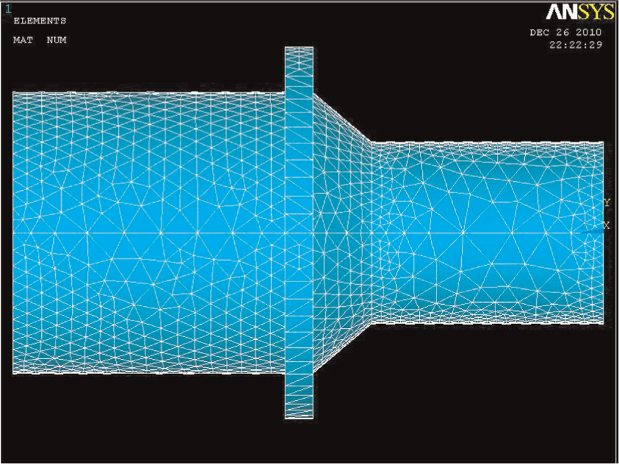
Booster meshing.
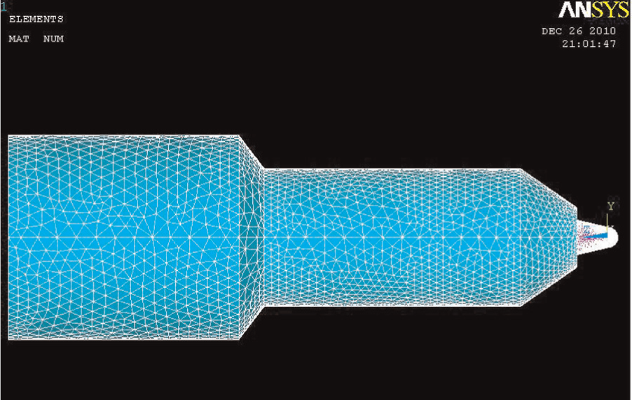
Horn meshing.
The mode of extraction method or solving method was defined by Block Lanczos in the ANSYS environment. This solver is used for symmetrical and especially large-value programs and has a faster convergence rate than other related solvers. Also, it can be used for models that do not have any regular meshing of solid and shell elements. To minimize the analysis time, the range of natural frequencies was set to 15–25 kHz and the number of modes to extract was set to 5.
The results of the simulation are shown in Table 4. As shown, only four modes were extracted from the final simulation. The results were obtained by changing the dimensions of the models of the booster and the horn. To manufacture the booster and the horn, the first extracted mode, that is, from 19.923 to about 20 kHz, was selected, and the outcomes were then estimated in the graphical environment of ANSYS. The final dimensions were extracted from the proper model designed.
Simulation results.
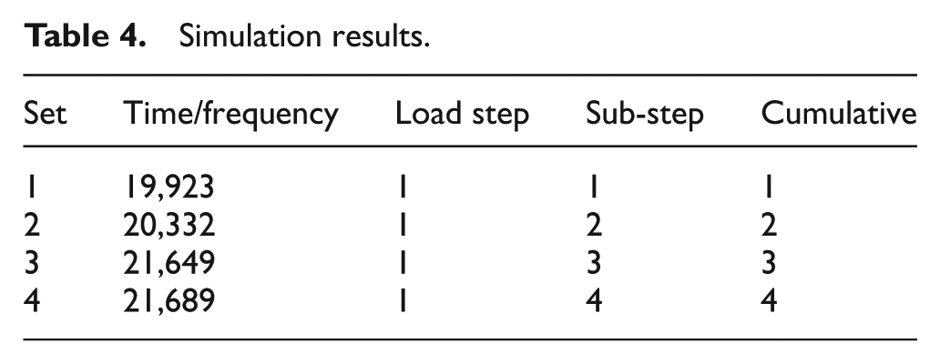
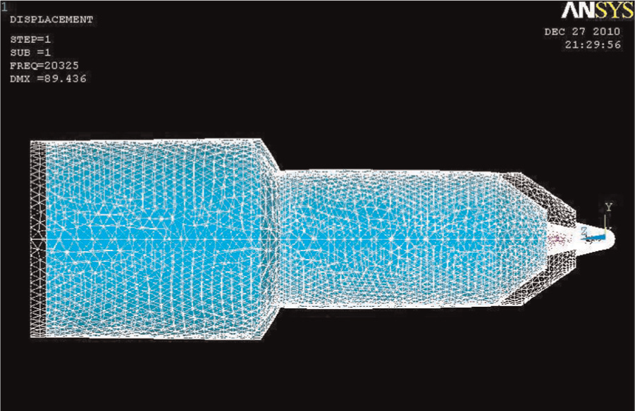
Figure 9 shows the overall displacement of the booster. As shown, the largest displacement contour occurred in the head of the booster parallel to its axis, showing that the booster increased the vibration value amplitude at a given frequency. On the other hand, no displacement is observed in the middle section of the booster, which is the node point of the vibration wave. Thus, the booster had to be fixed from this section toward the other parts of the ultrasonic system.
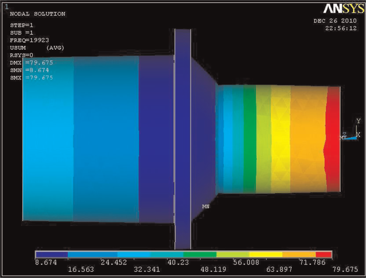
Booster overall displacement following simulation.
Figure 10 shows the deformed shape of the horn after simulation. Clearly, the horn also increased the vibration amplitude under the predefined frequency parallel to its axis and transmitted the vibrations to the horn. Based on the simulations performed by the ANSYS, the booster was made from AL7075T6 aluminum alloy in order to yield the strength required for vibration transmission. The booster and the horn thus manufactured are shown in Figure 11. The booster was connected to the transducer by a slotted headless screw on one side and to the horn on the other. Figure 12 shows the locations of the booster-to-transducer connections.
The deformed shape of the horn following simulation.
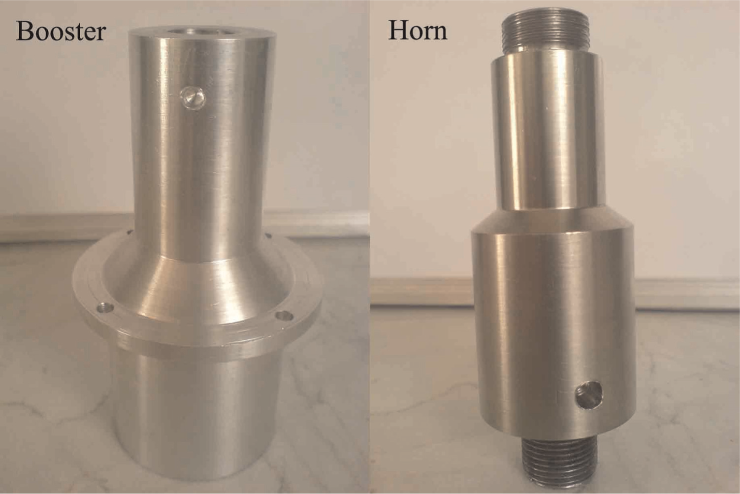
Manufactured booster and horn.
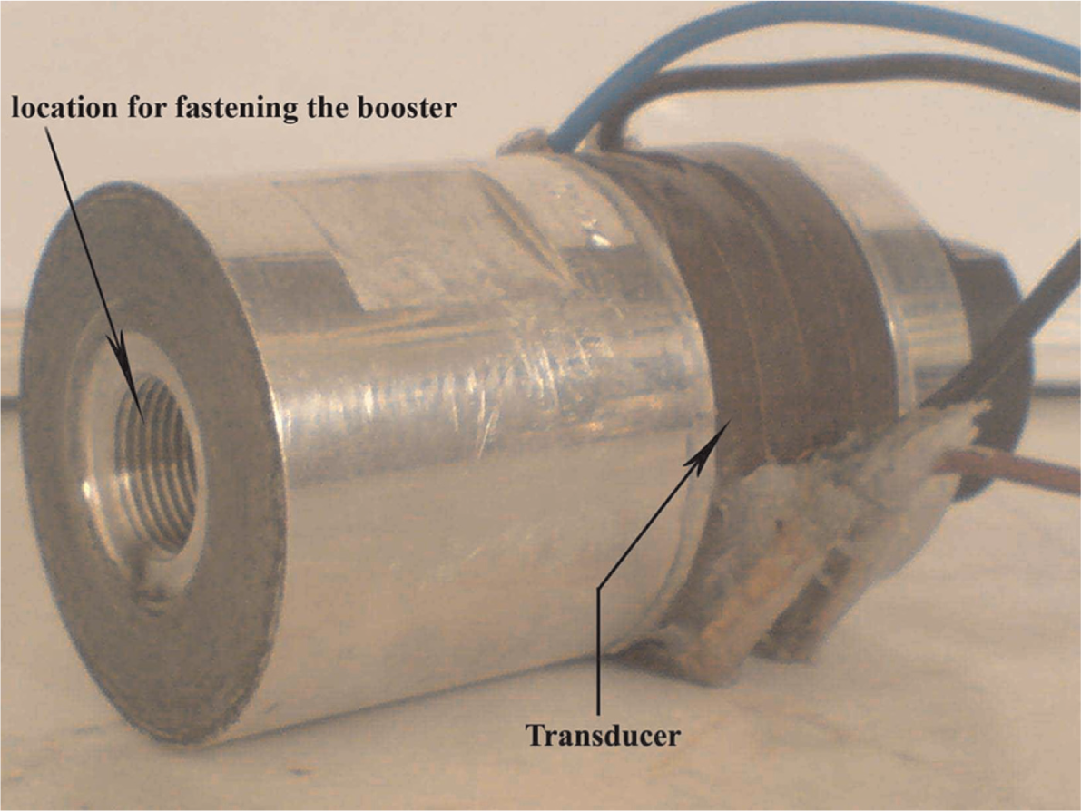
Location for fastening the booster to the transducer.
The booster was fastened to the front piston of the pneumatic system at the node point because, as noted, this part of the booster does not affect the mechanical vibrations. The connection between the ultrasonic head and the pneumatic system was made at this point. The horn was fabricated from TI6AL4V titanium alloy and connected to the booster at one side and to the tool and tool gripper at the other. Figure 13 shows the fabricated tool and tool gripper of the ultrasonic system.
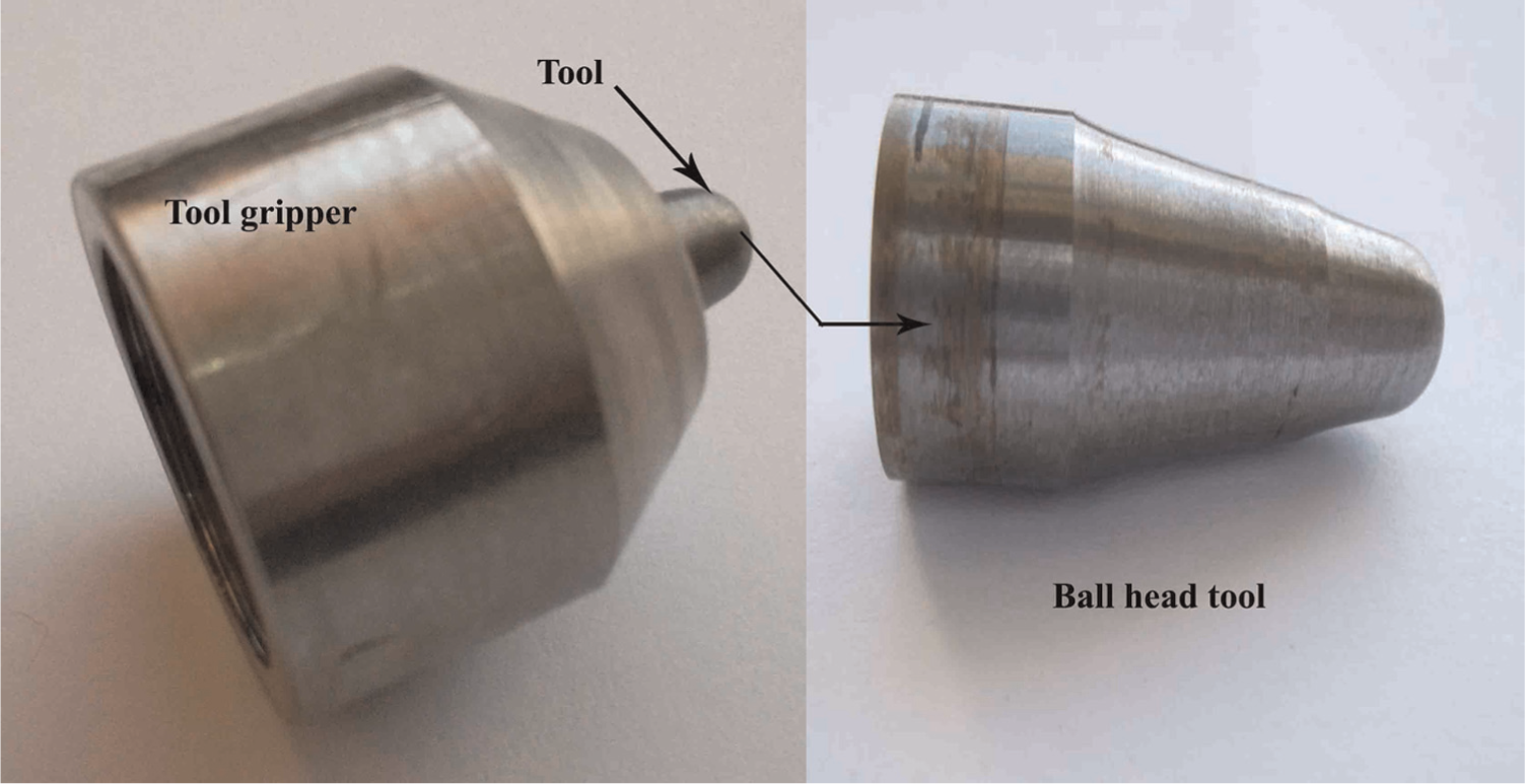
Tool and tool gripper.
Since the tool was made of tungsten carbide, it was hard to form threads on it; thus, the ball gripper was designed in a manner to hold the tool to the horn. Also, a ball gripper was devised to provide the capability for changing different tools.
Simulation of the UCFT process and design of a pneumatic system
In the UCFT process, the tool frequently strikes the surface crystals of the workpiece at a rate of 20,000 times per second. During this drastic plastic deformation, an outstanding increase occurs in the hardness and smoothness of the surface due to the flattening of uneven surfaces. Figure 14 indicates a schematic view of the ultrasonic peening.
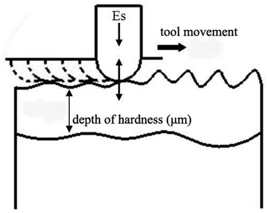
Ultrasonic tool functioning.
The total energy (Et) required for the UCFT process is determined by equation (1), where Es is the overall value of the static energy or input static energy behind the ultrasonic head, and Ed is the dynamic energy that is equal to the product of the amplitude of the dynamic load (F) and the sinusoidal function of the vibration wave
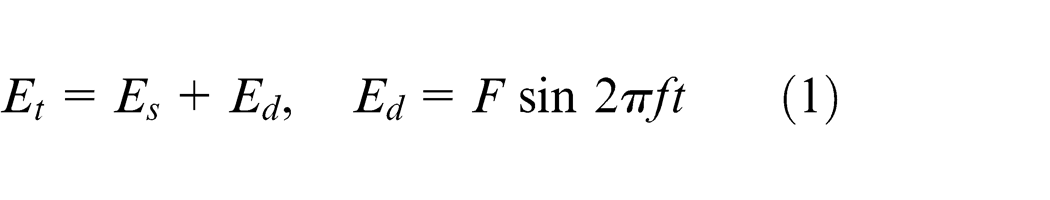
The ABAQUS software was used to simulate the UCFT process for its different advantages such as user-friendliness, precise analysis, powerful modeling, and high speed. 11 To reduce analysis time in the simulation, the tool and the workpiece were designed as two-dimensional (2D) models. Since the tool was manufactured from tungsten carbide, a semicircle 2 mm in diameter and analytically rigid in nature was assumed in a 2D planar environment. In addition, the workpiece was assumed to be deformable. The contact surfaces between the tool and the workpiece were designed in the form of toothed surfaces with a tooth height of 20 μm. Also, a plastic behavior was defined for the entire workpiece. The problem was solved in a dynamic explicit step. Furthermore, to move the workpiece in front of the tool, a velocity constraint was placed on the bottom of the workpiece. Also, for the tool to strike the top surface of the workpiece, a boundary constraint of the displacement type was applied to the reference point (RP) of the tool. This regular displacement was defined on the basis of both the sinusoidal function and the periodic type in the amplitude section using the ABAQUS software.
Meshing was applied to the workpiece using linear elements of Quad, namely, CPS4R and Tri (i.e. CPS3) applying a free technique. Figure 15 shows the final assembly of the tool and the workpiece within the ABAQUS software.
Final assembly of tool and workpiece.
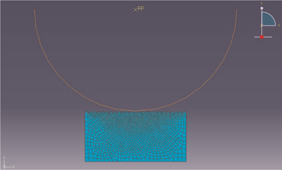
The main goal of the simulation was to determine the reaction force that has a direct effect on the mechanical properties of the surface, and it is defined as the reaction by the surface when it is stricken by the tool. The value of the reaction force in this simulation depends on the vertical displacement of the tool, the angle of impact, and the duration of impact. Figure 16 shows the maximum value of the reaction force during the analysis to be 15 kg f. The material of the workpiece and the working conditions are also additional factors that can vary the amount of the reaction force within a range of 7.5–20 kg f. 5
Reaction force obtained from the simulation results.
In order to compare the simulation and experimental results, a pneumatic system was designed to prevent backlash by the tool on the return stroke. In fact, when the tool strikes the workpiece, it withstands the force (reaction force) and creates a backlash in the tool. To calculate the reaction force in the experiment, the pressure applied by the air compressor behind the piston (2 bar) was multiplied by the piston area (7.06 cm2) according to equation (2)
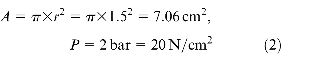
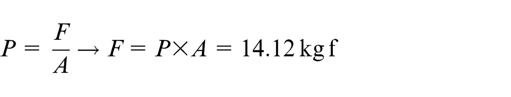
Thus, this reaction force (14.12 kg f) was neutralized by the pneumatic system. To calculate the piston diameter (3 cm), using equation (2), the nearest integer to the simulation results (15 kg f) was selected. Figure 17 shows the piston and the cylinder of the pneumatic system.
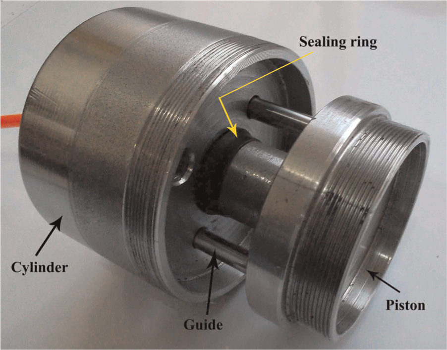
The piston and the cylinder of the pneumatic system.
A housing was designed as in Figure 18 for the booster to be attached to the pneumatic system and fitted in the fixture body. The booster was connected to the front part of the housing, and the piston of the pneumatic system was attached to its rear part. Also, the cylinder of the pneumatic system was connected to the main fixture. In addition, a phosphor-bronze belt was added around the housing for accurate movement of the three main parts (the ultrasonic head, the housing, and the piston) through the main fixture body. Thus, during the UCFT process, the piston could freely move through the cylinder and every backlash of the ultrasonic head could be neutralized by the air pressure behind the piston.
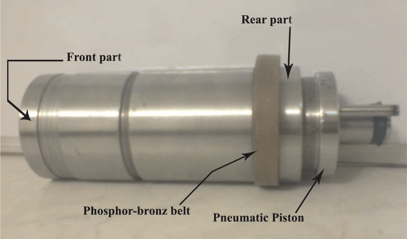
Housing designed to connect the booster to the pneumatic system.
Moreover, a comparison was made between the history of the kinematic energy and the internal energy to ensure simulation accuracy. The kinematic energy is typically 5%−10% of the internal energy. 11 The comparison is shown in Figures 19 and 20. It is seen that the maximum value of the kinematic energy was 0.45 J and the maximum value of the internal energy was 6 J. The displacement contour following the simulation is shown in Figure 21. The results indicate that the quality of the surface improved after the simulation.
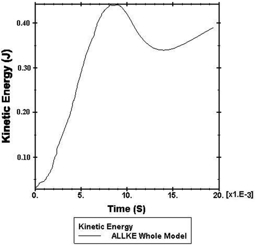
The kinematic energy supplied.
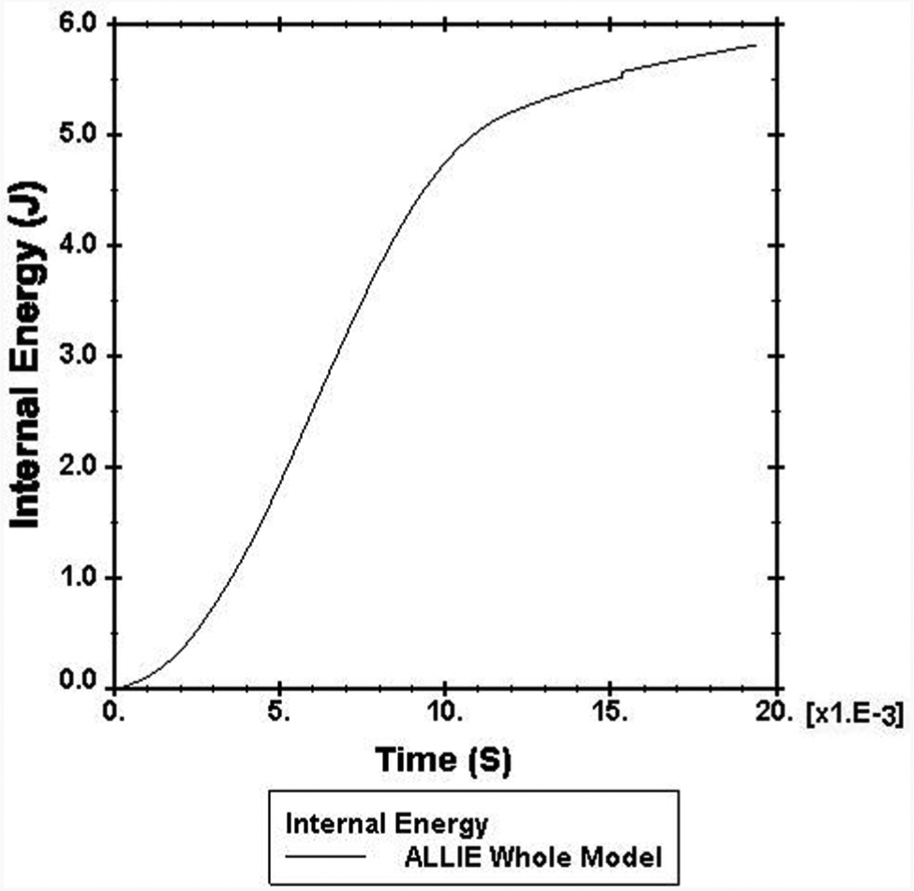
Internal energy supplied.
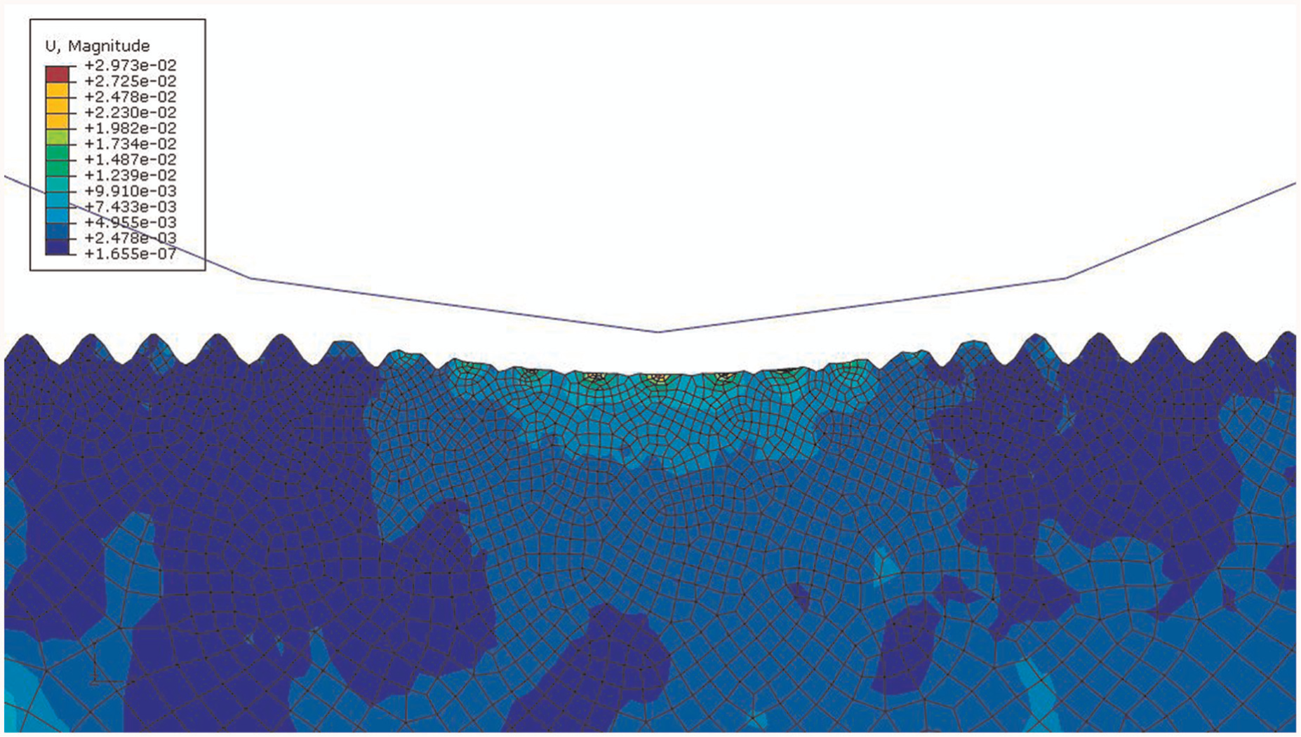
Contour displacement.
Mechanical tests following the process
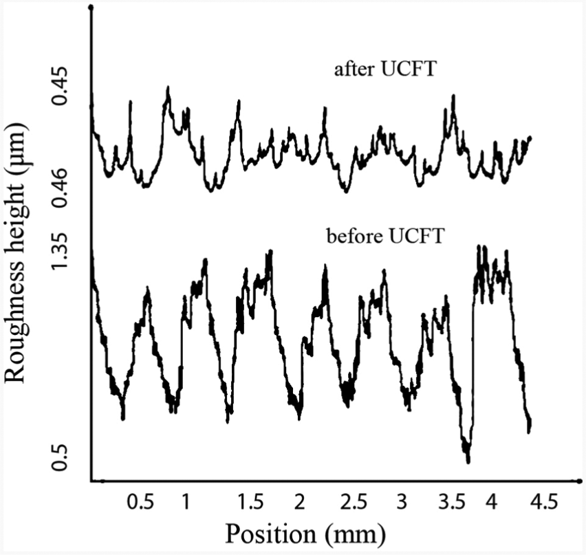
As already mentioned, the main objective of the UCFT process was to improve the mechanical properties of the surface. In other words, the process serves as a surface hardening method which flattens the uneven surfaces and compresses the layers into a hardened layer around the rod. Thus, it is expected that the smoothness and hardness of the workpiece will improve upon process completion. A digital surface roughness machine was used to control the smoothness of the workpiece. As shown in Figure 22, the overall smoothness of the workpiece was improved as required by the diagrams extracted. The primary smoothness of the surface was Ra = 0.6 μm which was improved to Ra = 0.132 μm as a result of this process.
UCFT effect on surface smoothness.
The Rockwell micro-hardness test method was employed to test the hardness of the workpiece. Figure 23 shows the surface hardness before and after the completion of the UCFT process. Clearly, hardness improved from 54.8 to 64.1 HRC. It must be noted that the improved hardness was achieved up to a depth of about 150 μm. Suh et al. 12 reported a 37% increase in hardness in their steel tools upon completion of the process.
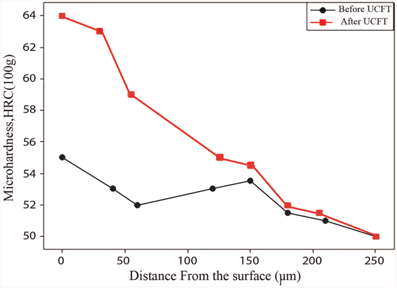
UCFT effect on hardness profile.
Conclusion
In this study, the effect of UCFT was investigated on hardening of surface layers. UCFT is an SPD method which compresses the surface layers of the workpiece by reciprocation and regular motions of the tool, whereby the tool repeatedly strikes the surface layers of the workpiece at a rate of 20,000 times per second using an ultrasonic system.
To manufacture the ultrasonic head (transducer, booster, horn, tool, and tool gripper) which converts the electrical energy into mechanical energy, a simulation was performed using ANSYS to determine the proper geometrical shape of the booster and the horn. In fact, the role of the booster and the horn (collectively known as the concentrator) in an ultrasonic system is to add to the amplitude of mechanical vibrations. Thus, simulation of the booster and the horn was accomplished based on the following considerations: (1) concentration of mechanical vibrations depending on the frequency produced by the ultrasonic generator (20 kHz) and (2) transmitting the mechanical vibrations in only one direction parallel to the axis of the tool but perpendicular to the workpiece surface. More than 50 simulations were run using ANSYS to determine all the dimensions of the booster and the horn as well as the exact location for fastening the booster to the housing.
Moreover, the UCFT process was simulated using ABAQUS to evaluate the effect of the tool on surface quality. For this purpose, a deformable workpiece with toothed surfaces was designed using the software, and the effects of striking the rigid tool on it were evaluated. Similar to the experimental results, the simulation results yielded a final smooth surface. Furthermore, a pneumatic system was manufactured for counteracting tool backlashes on the return stroke. Based on the statics principle, when the tool strikes the workpiece, a force is also exerted from the workpiece on the tool (called the reaction force) which will contribute to the tool backlash. The results obtained from ABAQUS showed that the value of the reaction force approached 15 kg f. Moreover, the value of the reaction force from the simulation was substituted in the pneumatic calculations to determine the diameter of the piston.
All the mechanical and pneumatic parts were designed, manufactured, and assembled with accurate precision. To install the ultrasonic head on the lathe carriage, a fixture was also manufactured. Also, to connect the mechanical and pneumatic parts, a housing was designed in such a way that it would allow the undisturbed movements of the piston inside the cylinder. Finally, the surface hardness and smoothness of the workpiece were measured accurately by mechanical tests. The results indicated improved hardness and smoothness following the UCFT process.
Footnotes
Declaration of conflicting interests
The authors declare that there is no conflict of interest.
Funding
This research received no specific grant from any funding agency in the public, commercial, or not-for-profit sectors.