
Abstract
This research aims to explore a better kinematic performance and design scheme for a novel mechanical leg using parameter optimization method. Serial structural mechanisms are widely employed in anthropomorphic mechanism legs but with significant disadvantages of the complex structure and large inertia, particularly, for the multi-objective parameter optimization it is hard to select good parameters to achieve excellent performance. In this article, the plane model of the solution space for multiple parameters and a novel statistics parameter optimization method were proposed for a novel mechanical leg. In the position analysis, the structure and workspace for the novel mechanical leg were developed with simple structure, small inertia, and large workspace; and several kinematic performance evaluation indices were also proposed in the kinematics analysis. In the parameter optimization process, the design scheme and prototyping of the mechanical leg have shown a better kinematic performance by considering the assembly technique as compared with the conventional models. The proposed research provides the basis for the applications of the novel mechanical leg, which can be applied in the modern humanoid robot fields to meet the requirements of high stiffness, lower inertia, and good technological efficiency.
Introduction
Humanoid robots are usually designed to model the human bodies, in which mechanical legs are indispensable if the robots are to walk and interact with the environment.1,2 Currently, most anthropomorphic mechanical legs adopt serial chains. For instance, the anthropomorphic robot developed by Solis et al. 3 has two legs and each leg consists of five serially connected links. Honda in Japan, Sarcos research team in the United States,4,5 University of Karlsruhe in Germany, and Beijing University of Aeronautics and Astronautics also developed various bionic mechanical legs with serial chains. However, serial chains suffer from several weaknesses in practical application, including small carrying capacity and large motion inertia.6–8 Compared with serial chains, robotic legs with parallel structure are compact and have large carrying capacity, which are increasingly promising to overcome the issues of serial chains,9,10 and can be used to conduct the precision polishing work using this kind of robot. 11 Thus, hybrid legs have been introduced in recent years. Liu et al. 12 designed a hybrid robot system for computed tomography (CT)-guided surgery. Wang et al. 13 developed a reconfigurable robot for the search and rescue purpose, including three identical robotic systems for performing distributed activities. Pisla et al. 14 proposed an active hybrid parallel manipulator (PM) for minimal invasive surgery and studied the structural design and kinematics of a parallel reconfigurable robot. 15
The optimal design of hybrid legs is one of the essential challenges to robotics community cause it is difficult to select appropriate parameters that ensure a good performance of the mechanical legs only by intuition or experience.16–18 Currently, there are two main approaches, namely, single-objective parameter optimization and multi-objective parameter optimization. The former study focuses on a single performance index while the latter investigation employs several performance indices as the objective function to optimize the parameters of the manipulator. Yue et al. 19 adopted the geometric model of the solution space technique to study the distribution of various structural parameters and performance indices. The structural parameters of micro-robot were optimized by Liu et al. 20 using the genetic algorithm. Hao and Merlet 21 proposed an optimization method based on the work space theory by considering the workspace and regarding other design objectives. However, these approaches must be initially optimized after the change of the objectives, and these approaches cannot visually and globally show the relationship between the objectives and design parameters as well. Further, the geometric model of the solution space is not suitable for the parameter optimization of the mechanism that has more than four structural parameters. To overcome these problems, the multi-parameter plane model technique was proposed and used for the parameter optimization of the mechanism that has more than four structural parameters, and it can synthesize multiple indexes based on multiple performances using the statistics method. Further, Ceccarelli 22 also conducted the research on designs and prototypes of mobile and humanoid robots, and presented a good performance. 23 Moreover, this kind of robot could enlarge the application of the precision machining technology24,25 in industry by combining with different mechanical structures.
Therefore, in this article it proposes a novel parallel anthropomorphic mechanical leg as described in the patent awarded by Li et al. 26 and the related parameter optimization method according to the plane model of the solution space for multiple parameters. The mechanism and structural features of the novel mechanical leg are first presented, and then the position and workspace analysis are conducted using mathematical approach, followed by analyzing the performance of the mechanical leg both in kinematic and static states. Further, the global performance atlases will be presented in detail to explore the distribution role of each structural parameter and the corresponding global performance index. Finally, the parametric design is carried out to obtain the parameter optimization for the mechanical leg.
Structural features of the novel anthropomorphic mechanical legs
A novel anthropomorphic mechanical leg with similar structure to human body was developed, which is driven by three motors to realize the movement of knee joint and ankle joint, respectively. The driving devices are placed on the fixed elements, so that the moving bars of this mechanism are not necessary to carry the weight of the driving motors, thus reducing the number of motors. Compared with conventional transmission system, this anthropomorphic mechanical leg owns the advantages of simple structure, strong carrying capacity, low moving inertia and flexible movement.
To be specific, the mechanism diagram of the anthropomorphic mechanical leg is shown in Figure 1. The mechanism is composed of a fixed platform, an active platform, and two kinematic chains. The two kinematic chains adopt the structural form of 2PUU/PRRRU, that is, the humanoid ankle joint is based on two identical branch chains PUU (Prismatic Pair-Hooke Joint-Hooke Joint) and the humanoid knee joint is based on a branch chain PRRRU (Prismatic Pair-Revolute Pair-Revolute Pair-Revolute Pair-Hooke Joint). It assumes that there are two coordinate systems {
Three linear moving pairs P1, P2, and P3 are parallel with each other which are all fixed on the base.
A driving motor controls the input displacement of moving pair P1 to achieve the rotation of rod FO2 around point F, thereby realizing the plane rotation of the humanoid knee joint.
Two drive motors, respectively, control the input displacement of the moving pairs P2 and P3 to achieve the plane JMN motion, respectively, thereby realizing the left and right rollover motion and the up and down pitch motion of the humanoid ankle joint.
The initial pose condition of the mechanical leg can be indicated that: (a) the rod FO2 is perpendicular to plane, MNO2, and parallel to rod FO1 and (b) the original lengths of P1, P2, and P3 are Li0 (i = 1, 2, and 3), respectively, and Δli is the corresponding input displacement.
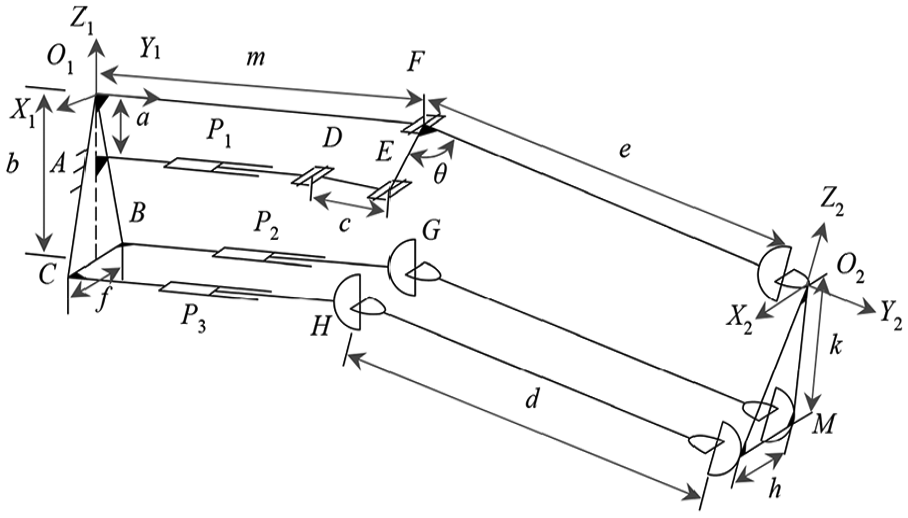
The structure of humanoid leg.
Position analysis
Position analysis is the fundamental to explore the mechanical movement capability and its applications in industry.
27
As shown in Figure 1, it is to set (0 y z)
T
and (α 0 γ)
T
as the position coordinate and posture coordinate of the reference point O2, respectively, and then it can determine the position vectors of A, B, C, D, E, F, H, and G in the static coordinate {

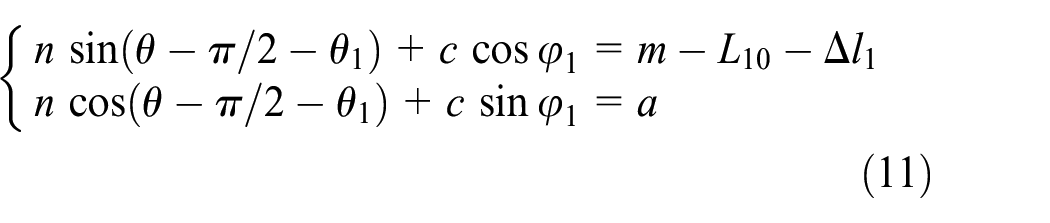
where n represents the length of rod EF and θ1 is the deflection angle of rod FO2 around point F (counter-clockwise rotation is positive and clockwise rotation is negative), and

Then, the position vectors of M and N in {

and the position vectors of M and N in {

where
The position inverse solution of this mechanism can be derived from equations (1) to (5) as follows
where D1 = m − nsin(θ − θ1 − π/2) − L10 and D1, D2, D3, D4, D5, and D6 are the functions of each structural parameter of the mechanical leg. For the anthropomorphic mechanical leg equation (6) is the expression of the position inverse solution of the knee joint and ankle joint, and is also the unique inverse solution.
Workspace analysis
Structural constraint
By setting
where


The minimum and maximum values of η1 are expressed as η1min and η1max, respectively, and are similar to η2 and η3. Then, the angle constraint of the mechanism can be described as

where

By setting the maximum and minimum input displacements of linear moving pairs, P1, P2, and P3, Limax and Limin (i = 1, 2, and 3), respectively, the length constraints of these linear moving pairs can be described as

Shape of the workspace
Workspace is defined as the set of points that a given reference point on the terminal executor can reach, and it is an essential performance index for structure analysis. It is to set the structural parameters of the knee joint and ankle joint, and the geometric structural constraint conditions according to Table 1. Thus, a workspace skeleton diagram can be drawn according to equations (1)–(9), as shown in Figure 2.
The structural parameters of humanoid leg.

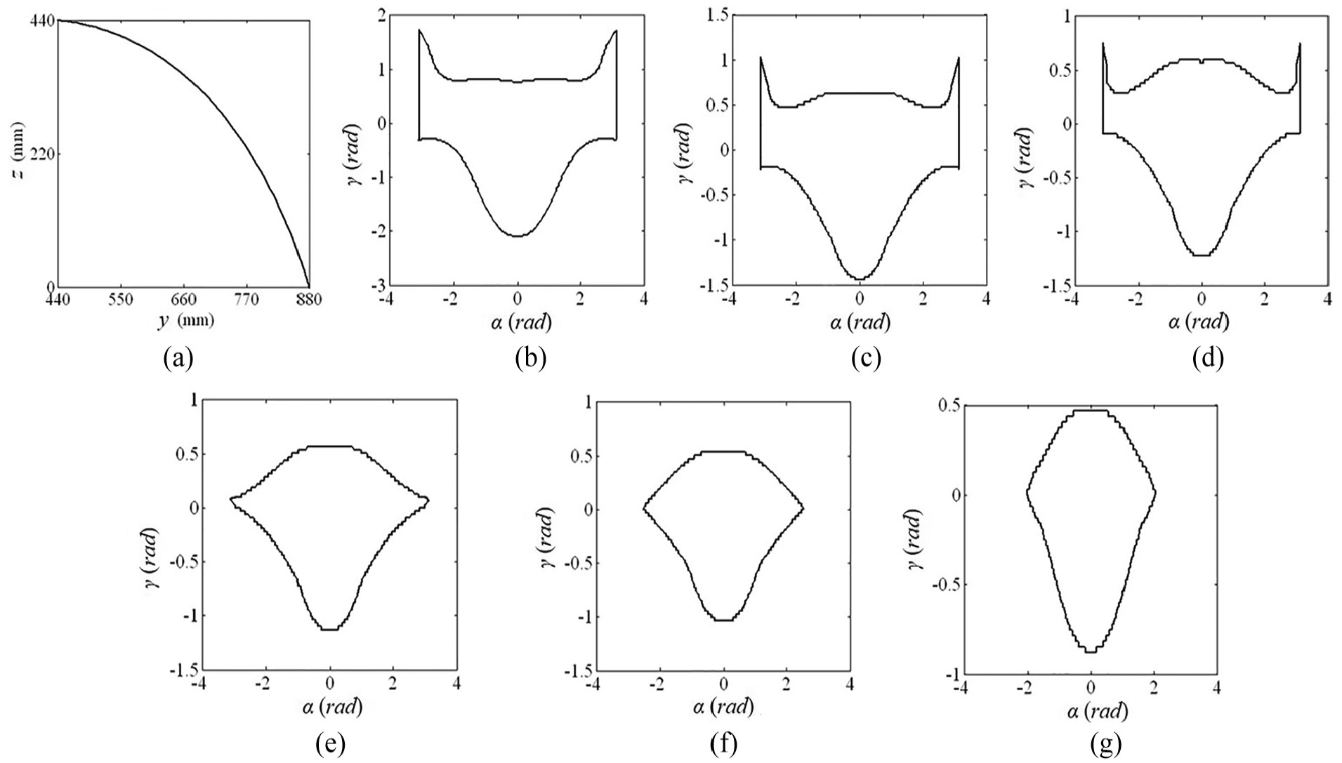
(a) Shape of position workspace and (b)–(g) shapes of workspace on different constant positions.
As can be seen from Figure 2(a) that the position workspace of the reference point of this anthropomorphic knee joint and ankle joint structure covers a quarter of a circle, and by combining with the findings from Figure 2(b) to (g) it can be indicated that:
The posture work space is symmetric about the α axis.
With the increase of z, the section of posture workspace decreases gradually.
With the increase of y, the range of α increases gradually.
The range of position workspace is 440 mm ≤ y ≤ 880 mm and 0 mm ≤ z ≤ 440 mm.
When y = 800 mm and z = 0 mm, the section of posture workspace is found to be the largest.
The approximate range of flexible posture workspace is −2 rad ≤ α ≤ 2 rad and 0.5 rad ≤ γ ≤ 0.5 rad.
The posture workspace is minimized when the mechanical leg is at the edge of the position workspace.
Effect of the parameters on the size of the workspace
To intuitively explore the effect of geometric parameters on the size of the workspace size in this mechanism, the workspace value (WSV), which is defined as the number of points that can be searched out in a certain step length, is employed to evaluate the size of workspace. The standard value of WSV is defined as W0 by setting the structural parameters according to Table 1, and then the workspace relative value (WSRV) can be expressed as

Thus, according to equations (1)–(10) the effect of structural parameters on size of the workspace size can be determined as illustrated in Figure 3.
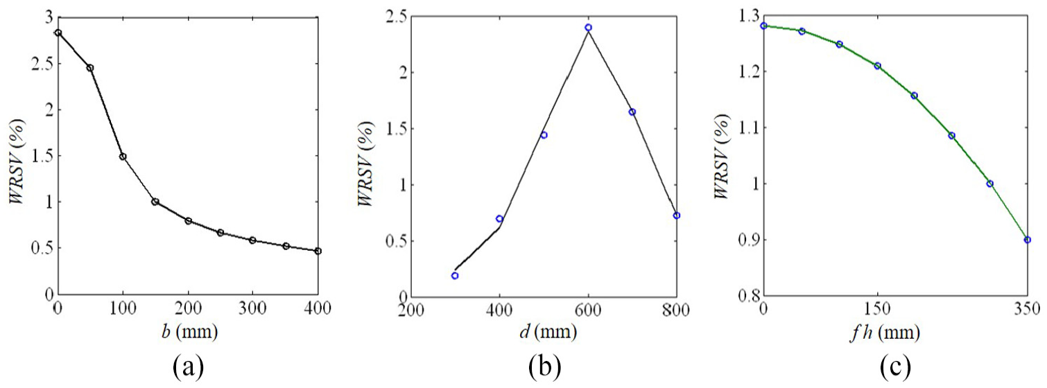
Effects of b, d, f, and h on the size of the workspace, respectively.
It can be found from Figure 3 that the overall effects of structural parameters on the size of the workspace, respectively. To be specific, it can be found that:
The WSRV decreases with an increase of b.
The WSRV decreases with an increase of f and h, respectively, in which f and h are the same length as shown in Figure 1.
When 200 mm ≤ d ≤ 600 mm, the WSRV could increase with an increase of d, however, when 600 mm ≤ d ≤ 800 mm, the WSRV could decrease with an increase of d.
When b and f increase, the decrease in the ratio of Δli to b or f will cause the range of activity of AR and BR to become smaller.
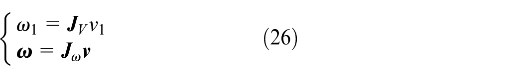
Kinematic performance analysis
It is to set
where φ1 is the rotation angle of the rod DE around point D. Taking a derivative of equation (10) with respect to time, the rotation angle speed of the coordinate FO2 around point F can be calculated as follows

where the counter-clockwise direction is positive for ω1, and vice versa. Then, the linear velocity vector of reference point O2 is expressed as

where

where

Based on the structural features of the knee joint and ankle joint, and by assuming the speed vector components of points M and N in the static coordinate as

where

It is to set

By combining equations (11)–(19), the following formula can be derived


and
Thus, it can derive the following formula from equation (20)

where


By considering that the linear speed vector

where

in which

When this mechanism is not in the singular pose, to consider that the linear speed and angular speed have different dimensions, equation (23) can be rewritten into the following form
where
Evaluation index of kinematic performances
When the mechanism is not in the singular pose, Jacobian matrix

where

By combining equations (24)–(28), it can obtain

where
According to equation (29), when the input speed is a unit vector, the output angular speed distributes in this ellipse, 28 and its axial lengths are σ1ω and σ2ω, respectively. To evaluate the speed transmission performance of this mechanical arm, the evaluation index of linear speed transmission performance and angular speed transmission performance, namely, KV and Kη, are defined as follows

where
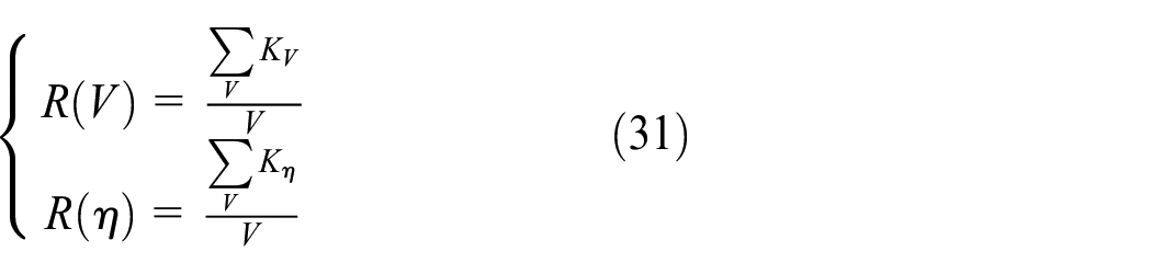
where V denotes the workspace of anthropomorphic mechanical leg and
Static performance analysis
It assumes that the base and each moving element are rigid bodies, and the friction force can be ignored. It is to set

where
The sum of virtual work done by external force

where

According to the principle of virtual work, when this mechanism is in the equilibrium state, the sum of all elementary work done by each external force equals zero, as follows

Virtual displacement

Moreover, by combining equations (32)–(37) the following formula can be derived

where

where

Static performance index
Since the force and moment have different dimensions, equation (39) can be rewritten into the following expression

where

where
where σ1 and σ2 are two singular values of
By combining equations (41)–(43), the following formula can be obtained

where
According to equation (44), when the input force is a unit vector the output force distributes in the ellipse29,30 with its axial length of σ1 and σ2, respectively. As the force Jacobian matrix

In the workspace of anthropomorphic mechanical legs, force and moment transmission performance evaluation indices have different values in different poses. Hence, the average values of KF and KM in the workspace of anthropomorphic mechanical leg are defined as the global force transmission performance evaluation index R(F) and torque transmission performance evaluation index R(M), respectively
where
Global performance atlases
To overcome the issues of current multiple parameter design methods, the plane model of solution space for multi-parameters technique is proposed. In this technique, more than four parameters are dimensionless, and each structural parameter is selected as side length to draw a polygon. Then, it is to draw vertical lines of each side crossing a point in the polygon, and define the intersection of each vertical line and the side as the value of structural parameter. Thus, the entire region within the polygon represents the set of all structural parameters, which can provide the distribution rule of each structural parameter and the corresponding global performance index.
This type of knee joint and ankle joint mainly have nine structural parameters as: a, b, c, f, θ, e, d, k, and h. Considering the structure form of anthropomorphic mechanical leg, structural parameter optimization of thigh and shank will be discussed in detail respectively. As h = f and k = b/cos(θ1/2), structural parameter, a, has no effect on the kinematic performances of entire anthropomorphic mechanical leg mechanism, so that the structural parameters are actually b, c, d, e, f, and θ. It is to establish the space model for the main structural size parameters of anthropomorphic mechanical leg, and make the structural size parameters dimensionless. First, it is to set

Then, k1 =b/P, k2 = c/P, k3 = d/P, k4 = e/P, k5 = f/P, and k6 = θ/P can be obtained. Considering the requirements of structure and assembly technology, it define the value range of k1, k2, k3, k4, k5, and k6 as

According to equations (47) and (48), it is to draw regular hexagon
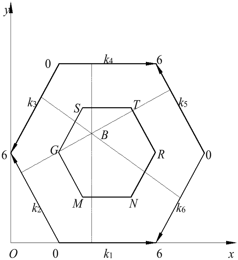
The plane model of multiple parameters for the mechanical leg.
Parametric design
To optimize the operating parameters in industry, different numerical and mathematical models are usually employed.31–34 In this study, the statistics parameters optimization method based on the plane model of solution space for multiple parameters is proposed for the mechanical leg. The method aims at multiple parameters which have uniformly distributed characteristics, and regarding the values of multiple evaluation indices as objectives. Then it selects proper parameters according to the model calculation and distribution regulation of the values of the statistical sampling, the proposed statistics parameters optimization method can be used to select reasonable structure geometric parameters.
As can be seen from Figure 5 that the maximum values of values of R(V), R(η), R(F), and R(M) are 0.9132 m/s, 1.1937 rad/s, 3.9086 N, and 4.0183 N m, respectively, while the minimum values are 0.3218 m/s, 0.2018 rad/s, 0.5321 N, and 0.3561 N m, respectively. It is to set the middle values of the performance evaluation indices as design objective, that is, R(V)=0.6265 m/s, R(η)=0.6978 rad/s, R(F)=2.2204 N, and R(M)=2.1872 N m. When R(V)≥0.6265 m/s, R(η)≥0.6978 rad/s, R(F)≥2.2204 N, and R(M)≥2.1872 N m, each performance evaluation index is perfect. By uniformly sampling in the range of main design parameters, the distribution rule of each parameter sample is obtained when the design objective is satisfied, and a frequency histogram is drawn as shown in Figure 6, in which horizontal axis denotes the value of structural parameter. By giving a structural parameter, many groups of parameter combination can be obtained, and the performance evaluation index for each structural parameter group can be calculated. Thus, the ratio of the group number of structural parameters that are better than the design objective to the whole group number can be obtained, and b, c, f, θ, e, and d are calculated in order to represent the probability of reaching the objective value.

Global transmission evaluation index atlases of the upper leg: (a)

Histograms of the parameters optimization for the humanoid leg: (a) histograms of length of b, (b) histograms of length of c, (c) histograms of length of f, (d) histograms of length of θ, (e) histograms of length of e, and (f) histograms of length of d.
In Figure 6, f(b), f(c), f(f), f(θ), f(e), and f(d) represent the probability of reaching the objective value. Through above analysis and the consideration of machining and assembly technology, the following structure geometric parameters are selected for this shoulder joint structure: b = 200 mm, c = 150 mm, d = 450 mm, e = 450 mm, f = 310 mm, and θ = 120°. In this way, f(b), f(c), f(d), f(e), f(f), and f(θ) have higher probability, R(V) = 0.8927 m/s, R(η) = 0.8763 rad/s, R(F) = 3.1856 N, and R(M) = 3.9201 N m.
According to the optimizing results for anthropomorphic mechanical leg and the consideration of machining and assembly technology, a design scheme is proposed as shown in Figure 7(a). This anthropomorphic mechanical leg is connected in series with a 3-degree-of-freedom (DOF) spherical parallel mechanism (serving as the prototype of hip joint mechanism), forming a design scheme of anthropomorphic lower limb as shown in Figure 7(b). The knee joint and ankle joint of this anthropomorphic mechanical leg mechanism adopt 4-DOF under-actuated mechanism as the prototype, and achieve the movement of knee joint and ankle joint by three motors. The fixed components such as motors are near waist, which contributes to the reduction of generated moment and moving inertia, and to the increase of the carrying capacity of leg. Thus, the advantages of parallel mechanism can be fully presented. Meanwhile, the lower limb of this anthropomorphic mechanical leg can achieve any gait and actively control various gaits. To sum up, this anthropomorphic lower limb exhibits several advantages, such as simple structure, strong load capacity, low moving inertia, and stable movement.

The design plan of the humanoid leg: (a) mechanical leg, (b) the biped robot, and (c) prototype of mechanical leg.
Conclusion
A novel anthropomorphic mechanical leg was proposed, and the plane model of solution space for multiple parameters and the statistics parameters optimization method based on the plane model of solution space for multiple parameters were proposed. Several kinematic and static transmission performance evaluation indices and global performance evaluation index were defined based upon the kinematic and static analyses.
The shapes of the workspace and effects of parameters on the workspace volume were drawn based upon the kinematics and static analyses of the novel mechanical leg, and the global performance evaluation index atlases were drawn based upon the plane model of solution space for multiple parameters.
When y = 880 mm and z = 0 mm, the volume of workspace is bigger. The posture work space is symmetric about the α axis and with the increase of z, while the section of posture work space decreases gradually.
According to kinematics analyses in the solutions of the plane models for multiple parameters, the maximum and minimum values of R(V), R(η), R(F), and R(M) are 0.9132 m/s, 1.1937 rad/s, 3.9086 N, and 4.0183 N m.
Considering the assembly technique, a design scheme and prototyping of mechanical leg was given by using the statistics parameters optimization method, and the present analyses provided a basis for applications of the novel mechanical leg.
Footnotes
Appendix 1
Handling Editor: James Baldwin
Declaration of conflicting interests
The author(s) declared no potential conflicts of interest with respect to the research, authorship, and/or publication of this article.
Funding
The author(s) disclosed receipt of the following financial support for the research, authorship, and/or publication of this article: This research was funded by Zhejiang Provincial Natural Science Foundation of China (No. LR18E050003), National Natural Science Foundation of China (Nos 51975523 and 51475424), and Shanghai Natural Science Foundation (No. 18ZR1417600).