
Abstract
Bearing stiffness directly affects the dynamic characteristics in a high-speed spindle system and plays an important role in terms of manufacturing quality. We developed a new approach for predicting the thermal behavior of a high-speed spindle, calculated the thermal expansion, and generated a bearing stiffness matrix for angular contact ball bearings. The heat convection of spindle housing in air, the balls in lubricant, the spindle shaft in quiescent air, and the bearing inner ring surfaces were determined. Heat sources such as bearing friction, and the heat contributed by the built-in motor, were simulated using an analysis systems (ANSYS) steady-state thermal model. The results were imported into a static ANSYS structural model. Ball thermal expansion was calculated based on changes in the coordinates of nodal points on the ball surface. Finally, a thermally affected bearing stiffness matrix was generated by applying the Newton–Raphson technique. Decreases in the bearing radial, axial, angular, and coupling stiffness values as rotational spindle speed increased were calculated. Also, the stiffness coefficients at a specific speed increased significantly caused by the thermal effects. Finally, for validation, the bearing stiffness was compared to that calculated using an earlier thermal network approach.
Introduction
Machining requires high-level precision. The dynamic spindle characteristics of a machining tool such as speed, torque, dynamic stiffness, and thermal expansion affect the throughput and quality of machining operations. It is difficult to eliminate heat generated by friction between the contacts of machine tool spindles. 1 Therefore, for the computation of the spindle bearing dynamic stiffness, it is essential to analytically model thermally affected parameters.
Palmgren 2 was the first to explore the relationship between bearing load and the corresponding displacement. Jones 3 determined inner and outer ring displacements according to the position of balls operating within a five degrees of freedom (DOF) support. The 5 DOF bearing loads were then developed using the model of De Mul et al., 4 who used a Jacobian matrix to solve the nonlinear contact force equations of bearings and defined ball contact stiffness using a five-by-five matrix. More recently, a 5 DOF, quasi-static Jones bearing model with different bearing configurations was used to study the stiffness characteristics of duplex angular contact ball bearings. 5 To obtain the five-by-five dynamic stiffness matrix, a finite element model 6 was constructed using LS-DYNA software to calculate bearing displacement and stress. However, thermal effects were not considered in these previous works, although heat generation within bearings may trigger failure and compromise the reliability, performance, and rotational speed of a machine tool spindle system.7,8
Burton and Staph 7 performed one of the first studies on the thermal behavior of angular contact ball bearings. To obtain the amount of thermal expansion in the angular contact ball bearings, Burton and Staph drew a heat-transfer diagram of the thermal resistance associated with deformation caused by elastic contacts. Stein and Tu 9 developed a state-space model based on the heat transmission laws governing different bearing configurations under various lubrication conditions. Heat sources, heat transfers, and sinks were included in the closed-loop, finite-difference thermal spindle model of Bossmanns and Tu. 10 Takabi and Khonsari 11 studied thermal behavior using a thermal resistance network to estimate the thermal expansion of bearing components. Recent studies12,13 created comprehensive thermal grid models to explore the thermal performance of angular contact ball bearings. Ye et al. 14 analyzed the thermally dynamic characteristics of angular contact ball bearings. Overall, although the various models introduced above used imaginative approaches to investigate thermal-mechanical behavior, the effects of heat on stiffness were not considered.
Jorgensen and Shin 15 further developed the model of De Mul et al. by adding a heat-transfer network to the spindle bearing system. Jorgensen and Shin combined the centrifugal expansion and inner ring-shaft thermal expansion into the ball and groove center separation in order to compute the ball bearing stiffness matrix. In addition, a finite element approach was taken, assuming that the spindle geometry was axis-symmetric. 16 Assessments of thermal behavior based on thermal networks have certain limitations; the thermal resistance network and associated calculations are not precise because the geometric factors in thermal resistance formula change with thermal expansion, especially for a multi-bearing motorized spindle system with complicated shapes.
In this article, we describe a workflow using an ANSYS steady-state model. This model simplifies observations of heat transfer within a spindle system. The thermal conditions of the model are determined based on the volume or surface area of the parts and include coefficients reflecting internal heat generation and convection. We used a finite element approach to solve the complicated multi-bearing spindle system. Thus, the drawbacks of thermal resistance networks are overcome. The model predicts the thermal behavior of an experimental spindle system and provides data on the thermal expansion of balls, the inner ring-shaft, and the outer ring-housing. These parameters can then be used to calculate bearing stiffness.
Bearing stiffness matrix
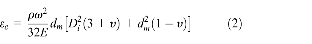
Centrifugal expansion
As spindle rotational velocity increases, the orbital speed of all balls in angular contact ball bearings also increases. The centrifugal force on each ball is in accordance with Harris 17

where j denotes the jth bearing ball at a certain attitudinal angle and
Ball loads and displacement
Figure 1 shows the loads acting on the ball, including the centrifugal force

where

where

where

Loads on a ball.

Thermal expansion and displacement.
The outer ring-housing thermal expansion is given by
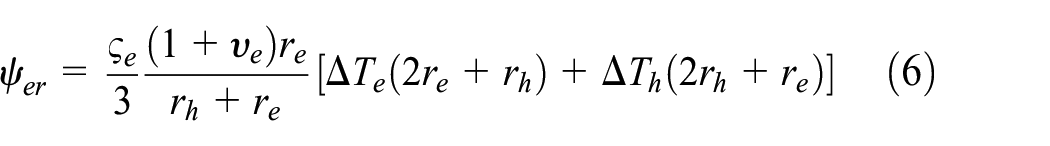
where
The Hertzian theory of spherical contact states that if the bearing ring contact forces

where

where

Parameters

where the subscripts a and b refer to the contact pair. In angular contact ball bearings, a contact pair refers to the contact between the ball and either the bearing inner or outer groove.
Local equilibrium equations
From Figure 1, the loads on the ball are given by

The Newton–Raphson technique is used to solve the nonlinear equilibrium equation (11) by considering changes

The Jacobian matrix of the local equilibrium equations is the derivative of the ball loads of equation (11) as the ball moves

By deriving partial derivatives and applying the chain rule, the elements of the Jacobian matrix of equation (13) are functions of the contact stiffness coefficients, bearing deformations, inner and outer contact angles, and thermal expansion


Global equilibrium equations
Figure 3 shows the bearing configuration of our experimental multi-bearing spindle system, in which a global Cartesian system (x, y, z) is used with the z-axis running along the bearing rotational axis; the origin is at the bearing centroid. A cylindrical system


Bearing configuration and coordinates.
Bearing stiffness is given by

The physical meaning and symmetric characteristics of the dominant terms in this matrix may be found in Li and Shin. 19
Thermal behavior
Bearing heat generation
Total friction torque
As the spindle rotates, the balls and the inner ring come into contact; the contact of the balls with the outer ring creates frictional losses and heat is thus generated. The amount of heat generated depends on the friction torque, which varies with spindle geometry, rotational speed, the type of lubricant, and the internal and external loads.15,17,19 The total friction torque is in accordance with Palmgren 2

where
After considering the inner and outer ring factors,


where
Using the

where k is the number of bearing rows and n is the number of balls in a bearing. For the angular contact ball bearings used here, k = 1.
For angular contact ball bearings,

where


where

Spin moment
Heat is also generated by the spin moment15,17,19

where
The major axes of the contact ellipses

where

Total heat generation
Heat generation in each contact area is given by Jorgensen and Shin 15
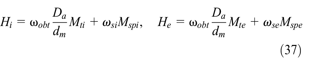
From equation (37), the total contact heat generation

The orbital velocity
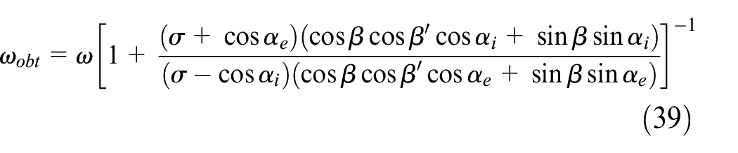

where

The angles

Rotational velocities and angles.
Heat contribution of the built-in motor
The specifications of the three-phase alternating current (AC) induction motor are listed in Table 1. The total heat generated by the motor is a function of the motor torque

where the motor efficiency

where
AC motor specifications.

Heat dissipation
Heat convection depends on the ambient fluid and solid body velocity. We consider the heat convection of a ball rolling in lubricant, the convection of a spindle rotating on its axis, and convection of the housing in ambient air.
Heat convection of a ball in lubricant
The convection coefficient of a ball at a certain orbital velocity is calculated using the Nusselt number. However, this number depends on the relationships among the Prandtl, Reynolds, and Grashof numbers. The Prandtl number is
We used an oil-mist lubricant, for which the heat convection coefficient of a ball is 15

Heat convection of the inner ring
The Reynolds number for the inner ring in lubricant is

For Re i < 4 × 10⁵, as in Harris, 17 the convection coefficient of the inner ring is

where Gr i is the Grashof number

where
Heat convection of the spindle
The rotation of a spindle shaft in quiescent air was given in Özerdem; 24 radiation is ignored so that the Nusselt number becomes

The spindle convection coefficient is then
Here, the spindle diameter
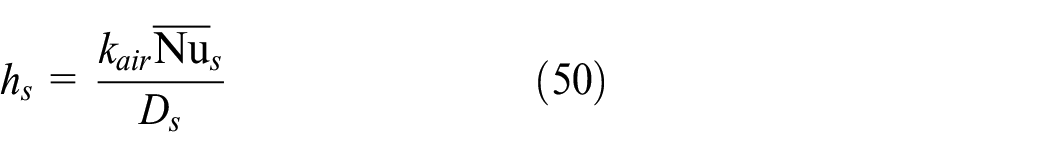
Heat convection produced by the housing
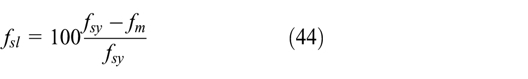
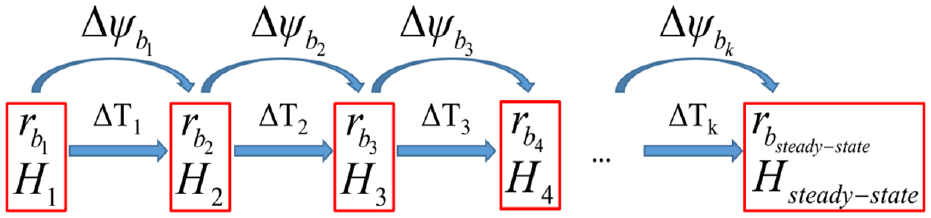
The heat convection coefficient of housing in air at room conditions is derived by measuring temperature changes15,17

where
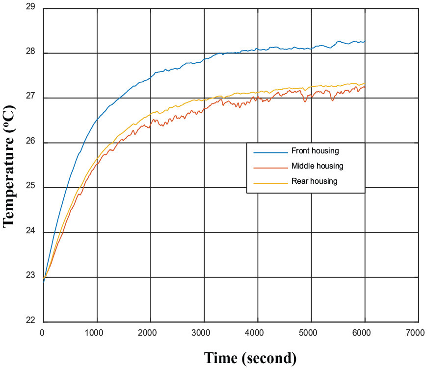
Transient temperature of the experimental spindle housing at a rotational speed of 5000 r/min.

(a) Heat generation by the motor and heat distribution to the stator and rotor, and (b) the heat generated by the bearings.
Figure 6(a) shows that heat is generated in the motor of the spindle system, principally in the stator.
Methodology and the ANSYS finite element model
Figure 7 shows the workflow for computing thermal effects on bearing stiffness in our spindle system. The entire procedure can be divided into two main stages: the first one is the computation of the thermal behavior of the spindle bearing system using an ANSYS finite element model; then, we use the thermally affected elements identified in the first stage to solve the bearing stiffness matrix by employing the Newton–Raphson method in the MATLAB environment.

Block diagram of the model.
In the first stage, the boundary conditions for the ANSYS steady-state model include heat generation, thermal dissipation, and the ambient temperature. The total heat generated is calculated by reference to bearing geometry, lubricant viscosity torque, orbital rotational speed, and the preloads and spin moments (equation (34)). The heat generated in the motor, and the distribution thereof, is shown in Figure 6(a). Heat dissipation is determined by considering the convection coefficients of balls in lubricant
After solving the thermal behavior, the thermal results were loaded into the ANSYS static structural model. For fitting a sphere through the coordinates of a set of points, at least four points on the spherical surface were collected. In this study, the coordinates of six nodal points on six regions of the ball surface were exported from the ANSYS static structural model to fit the radial changes (see Figure 8). For example, P01(x01, y01, z01) is the initial coordinate and P1(x1, y1, z1) is the final coordinate, after thermal factors are considered. As the coordinates are known, the ball radius can be computed using the sphere-fitting technique; the radius is approximated using six points. The thermal expansion

Nodal point coordinates before and after thermal displacement: (a) six-nodal point area, (b) initial coordinates, and (c) coordinates after deformation.
The steady-state thermal diagram.
Previous studies7,9,11,15,25 assumed that heat was transmitted equally from a ball to the bearing inner and outer rings. In fact, as balls rotate in a spindle system, heat is generated by friction torque. All nodal points on a ball surface contribute heat that affects thermal behavior via convection. Therefore, by fitting the ball radius using the coordinates of the set of points defined above (see Figure 8), thermal boundary conditions (the extent of internal heat generation) and physical conditions (changes in convection coefficients) are updated (see Figure 9); this overcomes a major limitation of previous thermal resistance networks.
Experimental system
Figure 10 shows the instruments used for data acquisition, the spindle simulator, and a cross-sectional view of the experimental spindle system. The front and rear regions have four NSK 7904C bearings and two NSK 7001C bearings, respectively. The stator, rotor, and air cooling systems of the motor are included. Temperature was measured using platinum PT100 resistance temperature detectors (RTDs) with three-wire interfaces (accuracy: ±0.5°C). RTDs were placed at the front, rear, and middle of the housing. Two more RTDs measured outer ring temperatures at the front (NSK 7904C) and rear (NSK 7001C) bearings. The RTDs were connected to an NI PXIE-4357 module of an embedded PXIE-8135 controller that sent data to a personal computer.
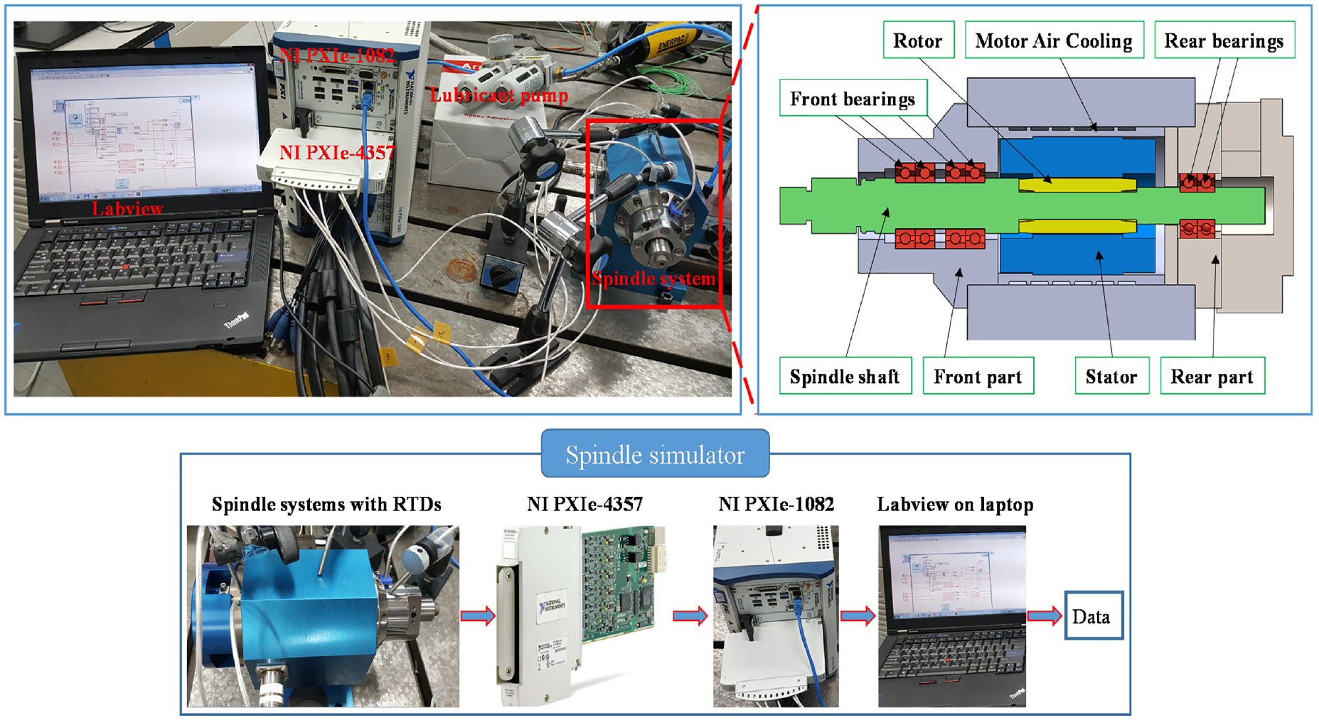
The experimental system.
Results
Bearing geometry
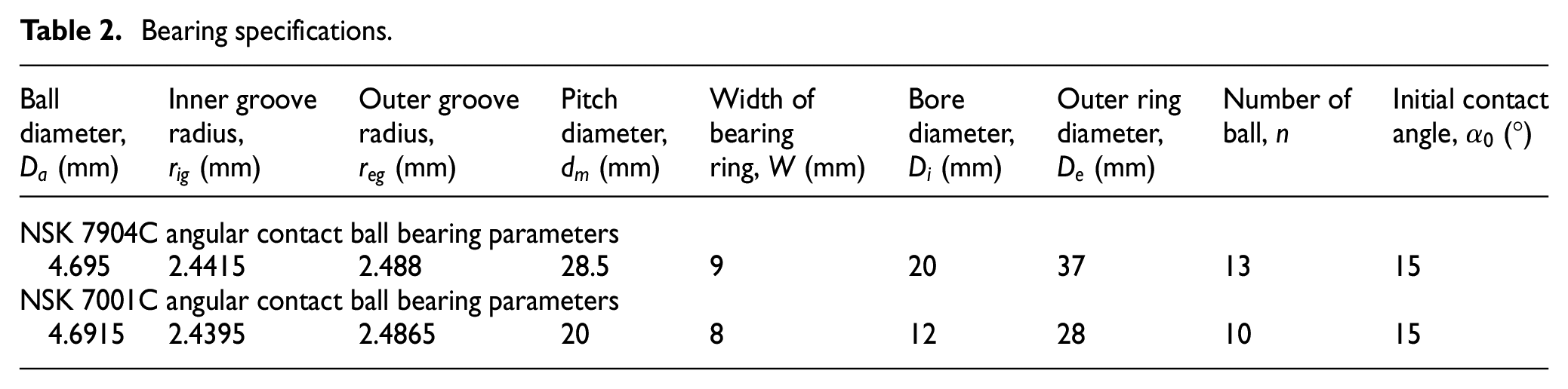
The geometry of angular contact ball bearings is shown in Figure 11(a). Friction torque between the balls and raceways generates heat. The ball diameter

(a) Bearing geometry and measurement of ball diameters: (b) points measured and (c) fitting.
Bearing specifications.
Thermal behavior of the spindle
The ANSYS steady-state thermal model is shown in Figure 12. The inputs were the heat distribution in the motor and rotor, heat generation within bearing balls, heat convection coefficients, and the initial (room) temperature. The specific boundary conditions of the ANSYS steady-state model at a spindle speed of 5000 r/min are listed in Table 3.

The ANSYS steady-state model.
Boundary conditions.
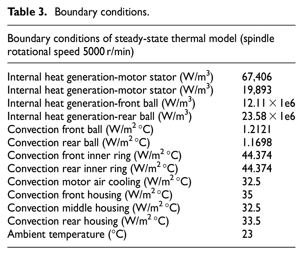
Figure 13 shows the simulated temperature changes at a spindle speed of 5000 r/min (see Figure 13(a)), and the transient temperatures measured at the bearing outer rings (see Figure 13(b)).

(a) Temperatures at a rotational speed of 5000 r/min simulated using ANSYS and (b) transient temperatures measured experimentally at the bearing outer rings.
Figure 13(a) shows that the temperature was approximately 33°C and 32.5°C at the outer rings of the front and rear bearings, respectively. Compared to the initial temperature of 23°C, the values are in good agreement with the experimental results shown in Figure 13(b). We then varied the spindle rotational velocity from 1000 to 10,000 r/min. Using the boundary conditions listed in Table 3, the process of the thermal analysis for different spindle speeds was repeated and the results were shown in Figure 14. Figure 14 illustrates that the temperature changes in the simulated and experimental results were very similar.

Simulated and experimental temperatures of the outer ring surfaces (front bearings) at different spindle rotational speeds.
After obtaining temperature data, ball radial thermal expansion was calculated by importing the body temperatures yielded by the ANSYS steady-state thermal model into the ANSYS static structural model, followed by fitting of the nodal point coordinates and computation of ball radii (see Figures 8 and 9). In the steady-state condition, the radial thermal expansion of balls in the front bearings is shown in Figure 15. Radial expansion of the inner ring-shaft and outer ring-housing was computed using equations (5) and (6), respectively.

Thermal expansion of the front bearings.
Bearing stiffness analysis
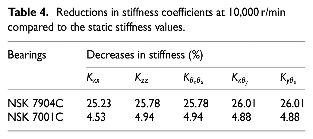
Changes in radial, axial, angular, and coupling stiffness values by spindle rotational speed are shown in Figure 16. The off-diagonal terms in equation (23) are negligible if there is only axial-internal preloading. The nine dominant terms include the radial stiffness values (

Elements of the bearing stiffness matrix according to the spindle rotational speed: (a) NSK 7904C and (b) NSK 7001C bearings.
Reductions in stiffness coefficients at 10,000 r/min compared to the static stiffness values.

Increases in the centrifugal force on the front and rear bearings as the spindle spools up.
The relationship between centrifugal force and the decrease in angular contact ball bearing stiffness was explained earlier. 22 As the spindle spools up, the balls experience centrifugal force (see Figure 1); the contact between the ball and the bearing inner ring is pushed up and out from the center of the inner groove center. This causes the increase in the inner ring contact angle and the decrease in the outer ring contact angle, which are shown in Figure 18. The increase in the inner ring contact angle results in the decrease in the inner ring contact force; the increase in outer ring contact force is attributable to the decreased outer ring contact angle (see Figure 19). Finally, the balls tend to move away from the inner ring, and the stiffness coefficients decrease.

The contact angles at the inner and outer rings of (a) the NSK 7904C bearing and (b) the NSK 7001C bearing.

The contact forces at the inner and outer rings of (a) the NSK 7904C bearing and (b) the NSK 7001C bearing.
Behavior differed markedly according to whether thermally induced bearing stiffness was considered. Figure 20 shows the difference in stiffness (
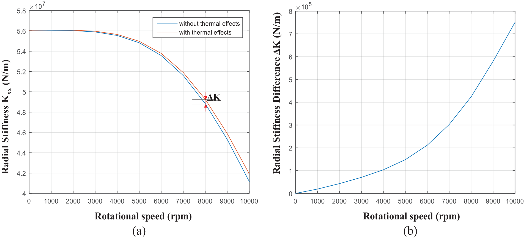
(a) Difference in stiffness according to whether thermal effects are considered and (b) the rises of the stiffness differences as speed increases.
For validation, Figure 21 compares the thermally affected radial stiffness values derived in this study for the NSK 7014C angular contact ball bearing to those of Jorgensen and Shin.
15
With the preload input

Comparison of our radial stiffness measurements to those of Jorgensen and Shin (NSK 7014C bearing).
Conclusion
We built a thermal model to estimate heat generation by, and thermal distribution to, the ball bearings in a high-speed spindle system. We combined steady-state thermal and static structural models on an ANSYS workbench. The temperature and thermal expansion of bearing balls were calculated by reference to changes in nodal coordinates, and the extent of heat generation was then re-calculated. We simulated and experimentally verified outer ring temperatures. This study improves our understanding of thermal behavior in spindle systems with complex geometry.
We constructed a five-by-five bearing stiffness matrix that included radial, axial, angular, and coupling stiffness. The dominant matrix terms decreased dramatically as spindle rotational speed increased, and thermal effects increased stiffness. We validated the model by comparing the radial stiffness values generated herein to those of a previous study.
Footnotes
Appendix 1
Acknowledgements
Handling Editor: James Baldwin
Declaration of conflicting interests
The author(s) declared no potential conflicts of interest with respect to the research, authorship, and/or publication of this article.
Funding
The author(s) disclosed receipt of the following financial support for the research, authorship, and/or publication of this article: This work was supported by the Technology Innovation Program or Industrial Strategic Technology Development Program (10060188, Development of ICT-based smart machine tools and flexible automation systems) funded by the Ministry of Trade, Industry and Energy (MOTIE, Korea).