
Abstract
Aiming at the complex structure and high manufacturing process requirements of traditional knotter, this article proposes a new rope knotting method. Based on the knotting method, a knotter is designed to use a new mechanism which is made up of two new incomplete gear mechanisms to drive rope clamping mechanism and rope hooking and griping mechanism. First, a kinematic cycle diagram of the knotter is determined, and the structures of each key mechanism are designed. Then, a virtual prototype of the knotter is established by Unigraphics and imported into Automated Dynamic Analysis of Mechanical Systems to analyze the kinematic of each key mechanism. The success rate is 98.4% through 500 physical tests on the physical model of the knotter. The results indicate that the knotting method is reliable. The knotter can meet the requirements of structure, posture, and coordination during knotting process. The new knotter has no separate mechanism for cutting rope and tripping out of the rope buckle. Therefore, the structure is simplified and reduces the design and manufacturing difficulties. Furthermore, the new incomplete gear mechanism solves the problem that in the conventional incomplete gear mechanism, the driven gear can swing at a large angle or even cannot be locked in the case when the locking arc of the passive gear is too short.
Keywords
Introduction
Knotter is the core component of agricultural equipment such as straw baler and sheaf binder. Its function is to knot the twine to tie the straw and the like. The performance of the knotter directly affects the performance of the corresponding agricultural machinery.
At present, D-bale knotters and C-bale knotters are widely used. The D-bale knotter is mainly composed of a frame, a driving dentate disk, a rope gripper, a knotting hook assembly, a transmission mechanism for driving the rope gripper, and a rope buckle take-off lever. The driving dentate disk of the C-bale knotter directly drives the rope gripper and the knotting hook assembly, and the rope buckle take-off lever is eliminated. All actions of the two knotters are driven by the driving dentate disk. The driving dentate disk of the D-bale knotter has two rows of teeth: one row of teeth drives the rope gripper, and the other row of teeth drives the knotting hook assembly. On the inside of the driving dentate disk, there is a cam for driving the rope buckle take-off lever to swing. The C-bale knotter has only one row of teeth on the driving dentate disk. This row of teeth drives the knotting hook assembly and the rope gripper. The two knotters use the same type of knotting nozzle, and the knotting nozzle rotates one full turn in each knotting cycle. In the process, the knot is opened and closed once to clamp the rope. The rope gripper of the D-bale knotter is a disk-shaped structure with grooves. After the rope is caught in the groove, the clamp disk rotates, and the clamping disk clamps the rope together with the auxiliary portion on the frame. The C-bale knotter’s rope gripper is a hoof-shaped structure with spring that can adjust the tension of the rope by a spring. A rope cutter is installed on the rope gripper, and the rope can be cut after the knotting is completed. The structure diagrams of the D-bale knotter and the C-bale knotter are shown in Figures 1 and 2.

The structure of D-bale knotter.

The structure of C-bale knotter.
These two knotters are commonly accepted for their ingenious original design and stable performance. However, the structures of these knotters are very complicated, and the requirement for manufacturing is high. Many researches have been carried out to transform and simplify their design and manufacturing process, and to improve and optimize their performance. These studies include the following: reverse reconstruction of knotter and optimization of some components,1–4 kinematic simulation and time series analysis of knotter,5,6 load analysis of key components,7,8 analysis of the spatial parameters of knotter,9–11 tension analysis of the twine, 12 and design of auxiliary device for knotter. 13 Some scholars have designed some new knotters.14–16
In terms of reverse reconstruction of knotter and component optimization. H Li et al. 1 took the D-twine knotter as the research objective. Based on the theory of reverse engineering, they designed a weight driving dentate disk with the features of high surface quality and stable transmission. H Li et al. 2 designed a φ-type knotter based on the D-bale knotter. Experiments on the test bench and field trials in wheat/maize fields have been carried out to check the knotting performances of the φ-type knotter. IM Kutlubaev 3 studied the manufacturing processes of products on bar rolling mills. He developed a mathematical model of operation of the knotting head, and improved the design of the head of the knotting unit. H Li et al. 4 studied the parameters of D-bale knotter driving pulley and designed two kinds of knotter driving pulleys. Experiments on the same operation conditions demonstrated that the new designed dentate disk is superior to that of the New Holland pulleys.
In kinematic simulation and time series analysis of knotter, Q Gao et al. 5 conducted the motion simulation of rigid-flexible contact interaction between the rope and the actuators of D-knotter under the environment of Automated Dynamic Analysis of Mechanical Systems (ADAMS). J Yin et al. 6 established a three-dimensional (3D) assembly model of the D-bale knotter and its auxiliary mechanism, and performed the kinematics simulation and time series analysis of enlacing and knotting process. Knotting principle of D-knotter was revealed.
In terms of load analysis of key components, Zhang and Yin 7 measured the compression of the compressed spring of the biting hook and the rope pulling force of the D-bale knotter. The best range of the biting force was determined as between 727.19°N and 835.89°N by mechanics model analysis of biting force in the biting phase. L Chen et al. 8 studied the load of the knotting hook during the process of straw baling, and found that the stress concentration happened at the shaft end of bill hook and corner.
In analysis of the spatial parameters of knotter, A Zhang 9 studied the correlation mechanism of the spatial structure parameters of the D-knotter and the influence of various parameters on the knotting action. He also analyzed the influence mechanism of each parameters. The main spatial structure parameters of the D-knotter were calculated and configured. J Yin et al. 10 analytically described knot-winding motion, rope-biting motion of the knotter, and timing sequence and position relation of rope-holding, knot-winding and rope-biting. It was found that the rope could be held firmly, wound successfully, and bitten accurately when the angle α between the knotting hook axis and principal axis on rope-holding motion is 24°, and the timing sequence difference value φ between the motion of knotting hook and the motion of rope-holding plate is 90°, respectively. H Li et al. 11 studied the spatial structure of the D-bale knotter based on its working sequence. Key spatial parameter relationships were determined to ensure the eight knotting processes going well through analyzing the knotter working principle.
In terms of tension analysis of bundled rope, JR McAfee et al. 12 developed a system to measure the tension of the top strands while baling a variety of crops with a high-density large square baler. They found that any design variations or strategies that reduce tension during the critical period when the bale exits the chamber could greatly reduce the requirement for maximum knot strength, and reduce the cost.
In design of auxiliary device for knotter, D Wang et al. 13 designed a rope winding mechanism for the steel-roller round baler. This enables the straw bales harvested by small and medium round balers, to expand and loosen easily.
In terms of developing of some new knotters, K Baldsiefen et al. 14 design a new type of knotter. The new knotter increases the tensile force of the twine under comparable conditions and enables higher bale densities. G Bernhardt et al. 15 design a new knotter system, which has two parallel knots forming units. The two knots are formed simultaneously. The equipment does not have a twine holder but it has a new needle drive. L He et al. 16 proposed a mechanical end-effector with multi-actuator for twining in high trellis hop production. The prototype of the end-effector allows automated knot-tying by mimicking human hands making a clove hitch knot using a sequence of coordinated string delivery and capturing actions.
Most of the above studies are theoretical studies of D-bale knotters, and there are very few original mechanical rope knotters. This article intends to throw out a brick to attract a jade and hope more people would join in the discussion.
The structure of knotter and knotting principle
The overall structure of the proposed knotter is shown in Figure 3, which is composed of a frame, a rope feeding mechanism, a rope clamping mechanism, a rope hooking and griping mechanism, and so on. The frame is the carrying part of the whole machine and can be installed on equipment such as a baler that requires the use of the knotter. The rope feeding mechanism is used to take the rope around the bundle and send it to rope clamping mechanism. In order to provide a possibility of subsequent knotting, rope clamping mechanism which stands as an important part of the knotter is used to fix two strands which are needed to be knotted. Rope hooking and griping mechanism is a core mechanism of knotter. It consists of two sub-mechanisms, including a rope hooking mechanism and a rope griping mechanism. It knots two strands of rope that are clamped by the rope clamping mechanism.

The structure of knotter.
The knotting process is divided into five steps, that is, feeding, clamping, hooking, gripping, cutting, and tripping out of the rope buckle. The workflow of knotter is shown in Figure 4.

The workflow of knotter.
The knotting method can be summarized as follows:
In initial state, one ending rope is passed manually through a clip that is open on the turntable and clamped by the other clip. Manual operation is no longer required after it is first completed. After the bounded object enters the binding area, the knotter begins to knot.
First, the rope feeding mechanism sends the other end of the rope to the knotted position. The two ropes are respectively brought together under the action of the tray on the rack and cambered fork on the rope sending rod.
Second, the rope clamp clamps two strands of rope. The knotting hook is rotated counterclockwise and hooked up two strands. After the knotting hook is turned 360°, the rope is wrapped around the knotting hook.
Third, the knotting hook continues to rotate while the movable jaw is slowly opening. After the part of two strands near the rope clamp is bitten into the movable jaw, the rotation is continued and the movable jaw gradually closes. After the knotting hook is turned over 495°, the movable jaw is completely closed and the two strands of rope are bitten.
Fourth, the knotting hook rotates 135° clockwise and returns to its original position. During the process, the rope is cut off by a cutter which fixed on the frame.
Fifth, the rope buckle wrapped around the knotting hook is taken off by the weight of the bound objects, completing the knotting process.
The actions of knotting hook and movable jaw during the knotting process are shown in Figure 5.
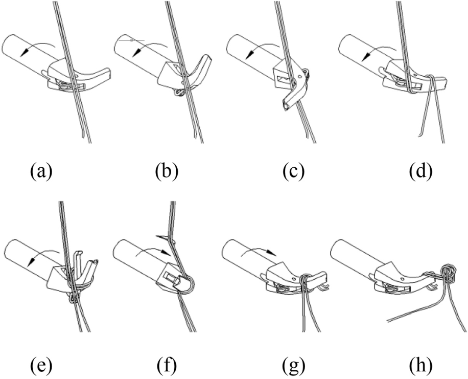
The schematic diagram of knotting process: (a)The knotting hook in the original state, (b)The knotting hook rotated 90°, (c) The knotting hook rotated 180°, (d) The knotting hook rotated 360°, (e) The knotting hook rotated 450°, (f) The knotting hook rotated 495°, (g) The knotting hook rotated back 135° to return to its original state and (h) The rope buckle was taken off.
Kinematic cycle diagram of the knotter
In a working cycle, the knotter completes five steps, that is, sending rope, clamping rope, hooking and gripping rope, cutting rope, and tripping out of the rope buckle. Accurate coordination between these steps of movement is required, and the timing sequence of the movement must be precise.
The action of tripping out of a rope buckle is completed by the weight of the bound objects and does not need help from another mechanism. In order to leave enough time for the other actions, the last 10° of the spindle rotation is set as the tripping time for each circle.
According to the previously described knotting process, in order to complete the actions of hooking and gripping rope, the knotting hook needs to rotate 630°. Taking the ratio of the spindle to the knotting hook of 1:3, the spindle needs to rotate 210° during the time of hooking and gripping rope. Taking the last 10° (350°–360°) for the tripping, the rotation degree of spindle between 140° and 350° is for the action of hooking and gripping.
The rope feeding is carried out by a crank and rocker mechanism. If the time of feeding trip is too long, the subsequent steps cannot be completed. On the contrary, if the time of returning trip is too long, it affects the feeding of binding material during the return trip, especially for continuous feeding of straw and branches. According to check calculation, the coefficient of travel speed variation of the four-bar mechanism should be 19/17, that is, the rope sending rod reaches the extreme position when the spindle rotates over 190°.
The rope clamping movement should be performed for a short period of time before and after the rope in place. After simulated analysis of the rope feeding mechanism designed in section “The design of rope feeding mechanism,” it is found that the appropriate timing of clamping rope is within 80° of the front and rear of the rope sending rod to pole position, that is, the rotated degree of spindle between 150° and 230°.
The cutting rope movement is completed by a cutter which is fixed on the frame during the reversal of knotting hook. The cutting operation takes place substantially when the spindle rotates 325°.
It is seen from the above discussion that the structure of the designed knotter is simple compared with the conventional design as there is no need for special mechanisms for twine cutting and bale tripping out. This will benefit simplifying manufacturing process.
The motion cycle diagram of knotter is shown in Figure 6.

The motion cycle diagram of knotter.
The design of key mechanisms
The design of rope feeding mechanism
Before the material is bundled, one end of the rope is clamped by the clamping mechanism. 17 After the material enters the area to be bundled, the other end of rope needs to be sent to the rope clamping. The initial state needs to be restored after an action is completed. A crank-rocker mechanism is selected because the structure of given rope needs to be periodically oscillated. In order to avoid interference with the feeding of binding material, the pendulum angle of rope sending rod is set as 110°. The length of rocker is set as L3 = 50 mm so as to reduce the dimension of the structure.
According to the motion cycle diagram of knotter shown in Figure 4, we get

From equation (1), we obtain

where
Under the above urgent response requirements, we obtained suitable parameters of four-bar mechanism. As shown in Figure 7, we can get

where L1 is a length of crank, L2 is a length of coupler, and L4 is a length of frame.

The structure of given rope.
The design of rope clamping mechanism
The function of the clamping mechanism is to fix the end of a rope when it is ready for a knot and to clamp the rope when it is in place. The rope clamping mechanism is composed of a turnplate, four clips, four rollers, a flange, and a matching portion. The rope clamping mechanism is shown in Figure 8.

The structure of hold rope.
Four clips are evenly hinged on a turnplate. Rollers are mounted on the clips which are opened when they are in contact with the flange. When the rope sending rod sends the rope to the open clip, the turnplate rotates and the roller are separated from the flange. At the same time, the matching portion is in contact with the outer edge of the clip and made the clip close. Eventually, the rope is clamped. After the turnplate has turned 90°, the other clip opens and is ready to begin the next cycle.
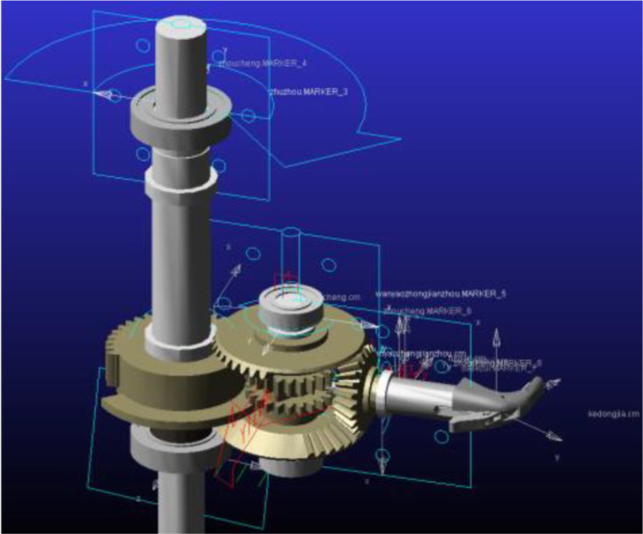
The design of rope hooking and griping mechanism
As shown in Figure 9, rope hooking and griping mechanism simulates human fingers to tie a rope and is the core mechanism of knotter. Rope hooking and griping mechanism mainly consists of seven parts, including a intermediate shaft of hook and grip, a driven incomplete gear of hook and grip, a cam, a movable jaw, incomplete bevel gears, a knotting hook, and a pushrod.
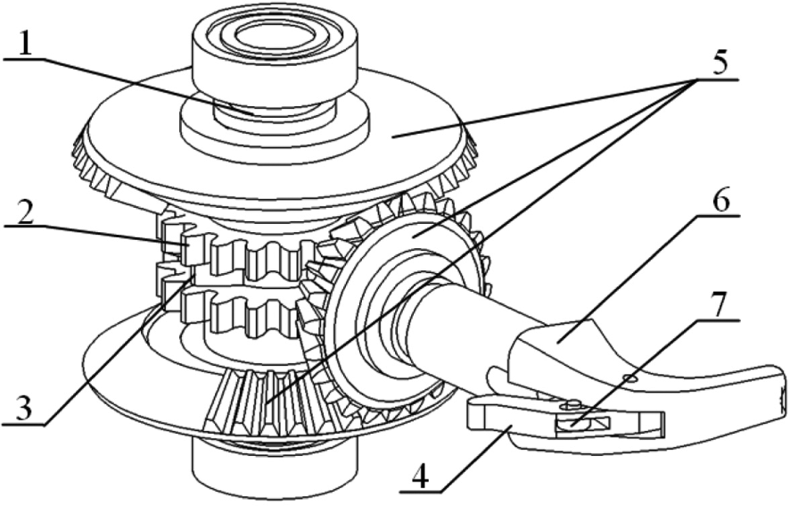
The structure of hook and grip.
The design of rope hooking mechanism
The intermediate shaft of hook and grip is installed with a multi-tooth incomplete bevel gear, a less-toothed incomplete bevel gear, a cam, and a driven gear of hook and grip. The multi-tooth active incomplete bevel gear meshes with the driven bevel gear to rotate the knotting hook in a counterclockwise direction. When the knotting hook is turned over 405°, the cam pushes pushrod to move, and then pushes the movable jaw to open. After that, the knocking hook continues to turn 90°. The movable jaw is closed after the ropes are bitten. As shown in Figure 5(f), the active incomplete bevel gear with less teeth meshes with the driven bevel gear and makes the knotting hook rotate 135° clockwise to return to the original position. During the process, the rope cutter that is mounted on the matching portion cuts the ropes off. As shown in Figure 5(g), after that, the rope buckle is taken off by the weight of the bundle, and the knot is closed.
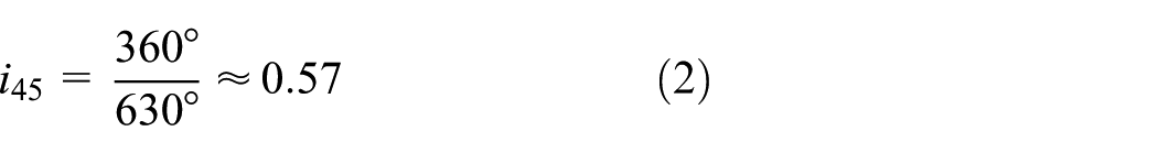
The process on the intermediate shaft of hook and grip rotates 360°, and the knotting hook rotates 630°continuously. Therefore, the transmission ratio from the intermediate shaft of hook and grip to the knotting hook is
The parameters of incomplete bevel gear set are shown in Table 1.
The parameters of incomplete bevel gear set.

The design on the cam with movable clip pushrod
During the biting time, the biting action is performed by the movable jaw.
17
And the opening and closing movable jaw is realized by the cam mechanism. In order to reduce the pressure angle, the motion angle for actuating travel
The design requirements of cam mechanism are shown in Figure 10. According to the analysis, the cam parameters are taken as


where

The designed requirements of cam mechanism.
In order to reduce the impact, the movement of actuating travel uses the sine acceleration curve. There is no load on the return travel. Hence, to simplify calculation, the constant velocity curve is selected.
The equation of cam pitch curve can be described as
where
The equation of cam contour can be described as
The contour curve of cam can be obtained by MATLAB as shown in Figure 11.

The curve of cam profile.
The design of driven system
All movements are driven by a spindle, and the movement of the rope clamping and the movement of the rope hooking and griping are intermittent. The intermittent movements are completed by two incomplete cylindrical gear mechanisms. The driven system of the knotter is shown in Figure 12.

Driven system of knotter.
In the rope clamping mechanism, the spindle drives the intermediate shaft for clamping rope to intermittently rotate through the incomplete cylindrical gear set. The movement of the rope clamping mechanism must cooperate with the rope feeding mechanism. Through simulating the designed rope feeding mechanism, it is found that the suitable rope clamping opportunity is within 80° before and after the rope is sent to the extreme position, that is, the spindle rotates through 80°. During this process, the turnplate for clamping rope rotates over 90°.
We can get


where
According to design requirements, we can get


where
From Kong, 18 we can calculate the parameters of the incomplete cylindrical gear mechanism in rope clamping mechanism as listed in Table 2.
The parameters of the incomplete cylindrical gear mechanism on rope clamping mechanism.

The center distance is 54 mm. The two-dimensinal (2D) engagement chart for the incomplete cylindrical gear sets of rope clamping mechanism is shown in Figure 13.

The 2D engagement chart for incomplete cylindrical gear sets of rope clamping mechanism.
The intermediate shaft for clamping rope drives the rope clamping turntable to rotate through the bevel gear set. The transmission ratio of bevel gear set is
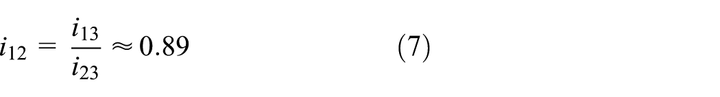
In the rope hooking and griping mechanism, the spindle is intermittent rotation through the incomplete cylindrical gears. According to the requirements of motion timing diagram, the spindle rotate through 210° and the intermediate shaft for hooking and griping rope needs to be turned 360°.
Hence, the actual transmission ratio of the spindle to the intermediate shaft for hooking and griping rope is

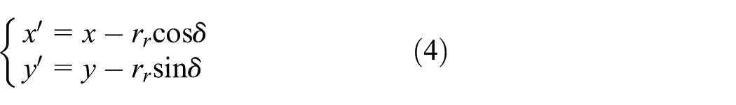
According to design requirements, we can get


where
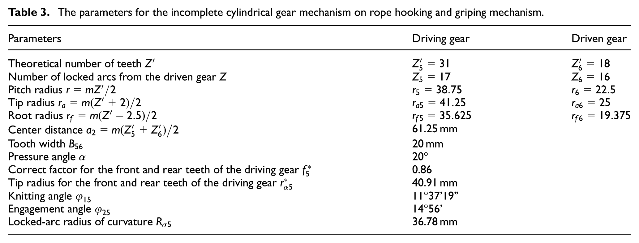
From Kong, 18 we calculate the parameters for the incomplete gear mechanism on structure of hook and grip as shown in Table 3.
The parameters for the incomplete cylindrical gear mechanism on rope hooking and griping mechanism.
The center distance is 62 mm. The 2D engagement chart of incomplete gear set of rope hooking and griping mechanism is as shown in Figure 14.
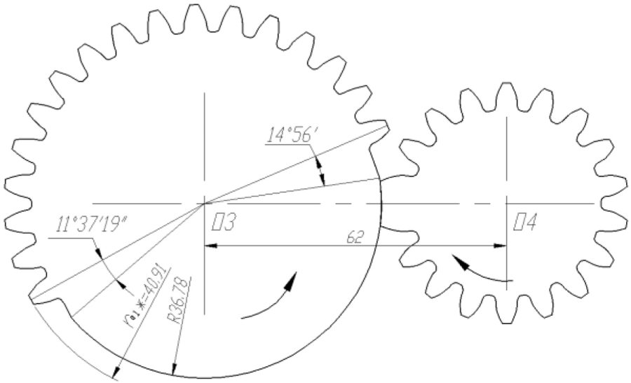
The 2D engagement chart of incomplete gear mechanism of rope hooking and griping mechanism.
Optimization for incomplete gear mechanism of driven system
The presence of engaging clearance would affect the nonlinear characteristics, including resonance amplitudes, jump frequency, overlap width of primary resonance, and degree of chaos. 19
The designed length of the locking arc of the gear is quite short. When the center distance is more than the designed value due to installation error, large oscillation would occur to the driven gear, or it even cannot be locked. In order to simulate this situation, the incomplete cylindrical gear set of rope hooking and griping mechanism models is set up and then set the center distance of 54.5 mm and 55 mm to make kinematics analysis in ADAMS software.
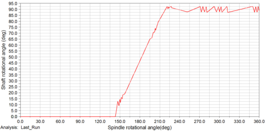
The simulated relationships between the intermediate shaft rotation angle and the spindle rotation angle for the cases of 54.5 mm and 55 mm of center distance are shown in Figures 15 and 16. It can be found that when the center distance is set to 54.5 mm, the driven gear swings at a large angle after the driving gear and driven gear are disengaged. When the center distance is increased to 55 mm, the driven gear cannot be locked after the two gears are disengaged. The driven gear continues to rotate under the action of inertia., that is, the locked arc loses locked function.

When the center distance is 54.5 mm, the curve of intermediate shaft for clamping rope rotational angle with the rotational angle of spindle.

When the center distance is 55 mm, the curve of intermediate shaft for clamping rope rotational angle with the rotational angle of spindle.
In same reason, the same problem exists in the incomplete gear mechanism for hooking and griping rope.
In order to solve the problem, a new type of incomplete gear mechanism with a locking flange is proposed as shown in Figure 17. The locking arc is lengthened to enhance the locking effect by adding a flange to each gear. Except to the curvature radius of the locking arc, the other parameters of the incomplete gear mechanism are the same as the conventional incomplete gear mechanism.

The 3D model of new incomplete gear mechanism with locking flange.
Both the radius
Through ADAMS simulation, it is found that the unidirectional pendulum angle of the driven gear need to be less than 3° in the non-engaged state for the mechanism to meet the functional requirements. When the center distance is 55 mm and the wrap angle of curve-locking is β ≥ 50°, the unidirectional pendulum angle of driven gear in the non-engaged state is less than 3°. We can take

The 2D engagement chart of the new incomplete gear set for clamping rope mechanism: (a) top view and (b) upward view.
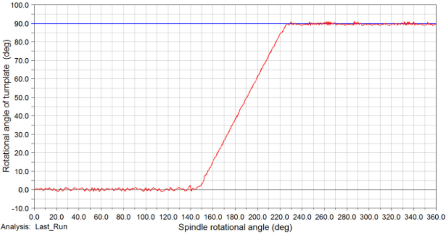
The curve of intermediate shaft for clamping rope rotational angle with spindle rotational angle when the center distance is 55 mm after optimization.
A pair of locking flanges are also added to the incomplete gear mechanism for hooking and griping rope to ensure proper performance.
Key mechanisms simulation and analysis
Analysis of motion for rope feeding mechanism
The rope feeding mechanism is a crank-rocker mechanism which satisfied the coefficient of travel speed variation at 19/17. In addition, the rocker should be satisfied the required pendulum angle to 110°. Import the model into ADAMS software established by Unigraphics (UG). And then set up parameters of materials, gravity, workspace, work unit, constraints, motion pair and drive, and so on, as shown in Figure 20.

The simulated model of the rope feeding mechanism.
After the simulation analysis, a curve of pendulum angle of rope sending rod with the rotational angle of spindle is shown in Figure 21. It can be found that when the spindle rotates through 190°, the rope sending rod just swings to extreme position of 110°, which meets the design requirement.

The curve of pendulum angle change of rope sending rod with the spindle rotational angle.
Simulation analysis of rope clamping mechanism and its driven system
According to design requirements, for every revolution of the spindle, the turnplate for clamping rope should be rotated through 90°. Then the clips on the turnplate should have one closed and the other opened. The structure of rope clamping mechanism is designed in section “The design of rope clamping mechanism.” The pendulum angle of clip is 50°. Import the model into ADAMS software established by UG, and then set up parameters of materials, gravity, workspace, work unit, constraints, motion pair and drive, and so on, as shown in Figure 22.

The simulation model of rope clamping mechanism and its driven system.
We can get the curve of rotational angle of turnplate for clamping rope changing with the rotational angle of spindle as shown in Figure 23. It can be found that when the spindle rotates between 150° and 230°, the turnplate for clamping rope rotates through 90° which meets the requirements of motion cycle diagram. During this process, the curve of clip rotational angle with the rotational angle of spindle is shown in Figure 24. And then the clip is rotated to 50° which is also consistent with the design.
The curve of the rotational angle change of turnplate for clamping rope with the spindle rotational angle.

The curve of the clip pendulum angle with the spindle rotational angle.
Analysis of rope hooking and griping mechanism and its driven system
According to design requirements, for each revolution of the spindle, the knotting hook is rotated 495° counterclockwise and then rotates 135° clockwise. Import the model into ADAMS software which was established by UG. And then set up parameters of materials, gravity, workspace, work unit, constraints, motion pair and drive, and so on, as shown in Figure 25.
Simulated model of structure of hook and grip and its driver system.
After simulation analysis, a curve of rotational angle of knotting hook with the rotational angle of spindle is shown in Figure 26. It can be found when the spindle rotates to 140°, the knotting hook starts to rotate. When the spindle is turned to 305°, the knotting hook is turned over 495° and then starts to return back. When the spindle rotates through 350°, the knotting hook is just turned back 135°. It is in line with a motion cycle diagram and design requirements.

The curve of the rotational angle change of knotting hook with the rotational angle of spindle.
Experiment
In order to verify the running effect of designed knotter in this article and whether it can meet the functional requirements, a physical model of knotter is made.
After all the parts of the knotter have been machined, the individual components of the knotter are assembled at first. Then, the components are assembled together. The frame and each component are machined with threaded holes which are matched with each other during assembly. Next, the mechanism of rope sending rod is adjusted to the far pole position before assembly. And then, the mechanism of clamping rope is adjusted to one of the clips to be opened. Finally, it should be adjusted that the opening direction of the knotting hook should be perpendicular to the spindle axis, so as to ensure the mechanism in the initial position. The assembly process is shown in Figure 27. The physical model of the knotter is shown in Figure 28. In practice, the rope clamping mechanism and rope hooking and griping mechanism are driven by one spindle. Then, the rope feeding mechanism is driven by a shaft synchronized with the spindle. To simplify the model, the physical model uses the same spindle to drive all mechanisms.
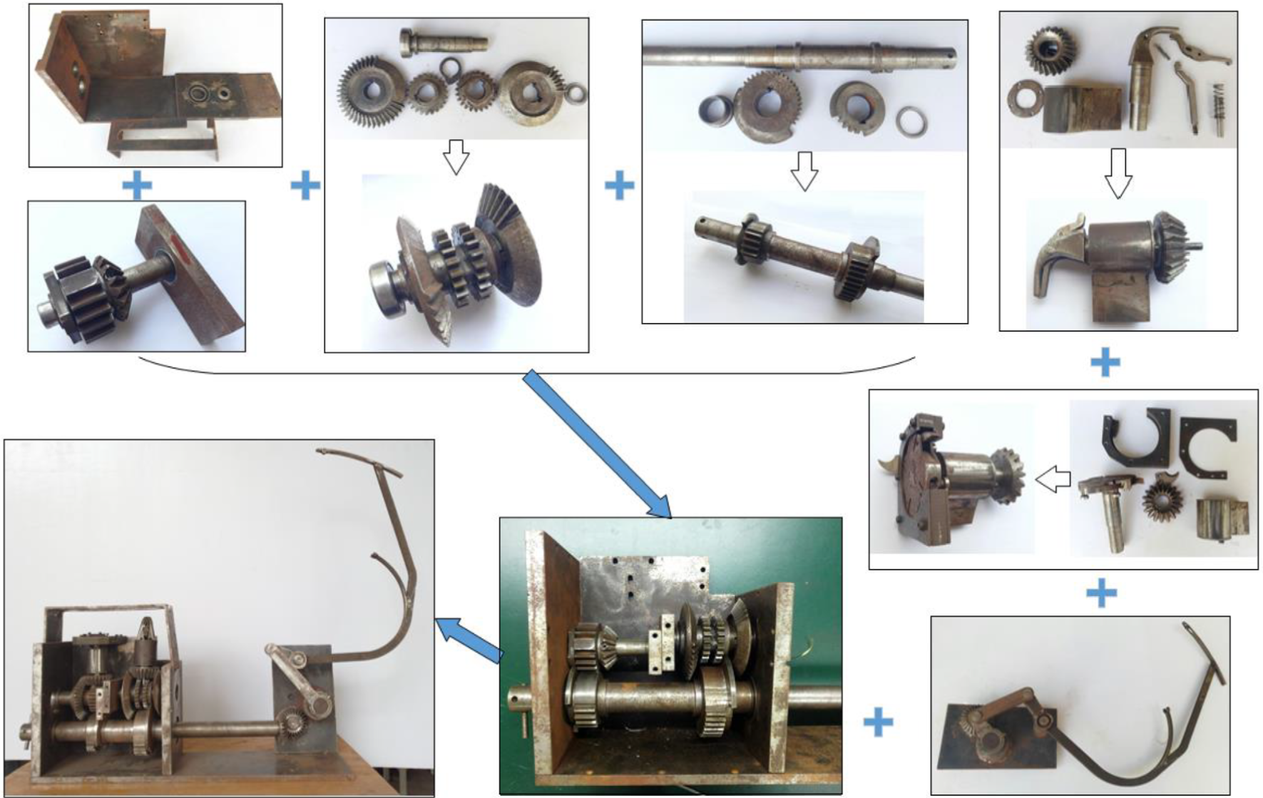
Assembly process.
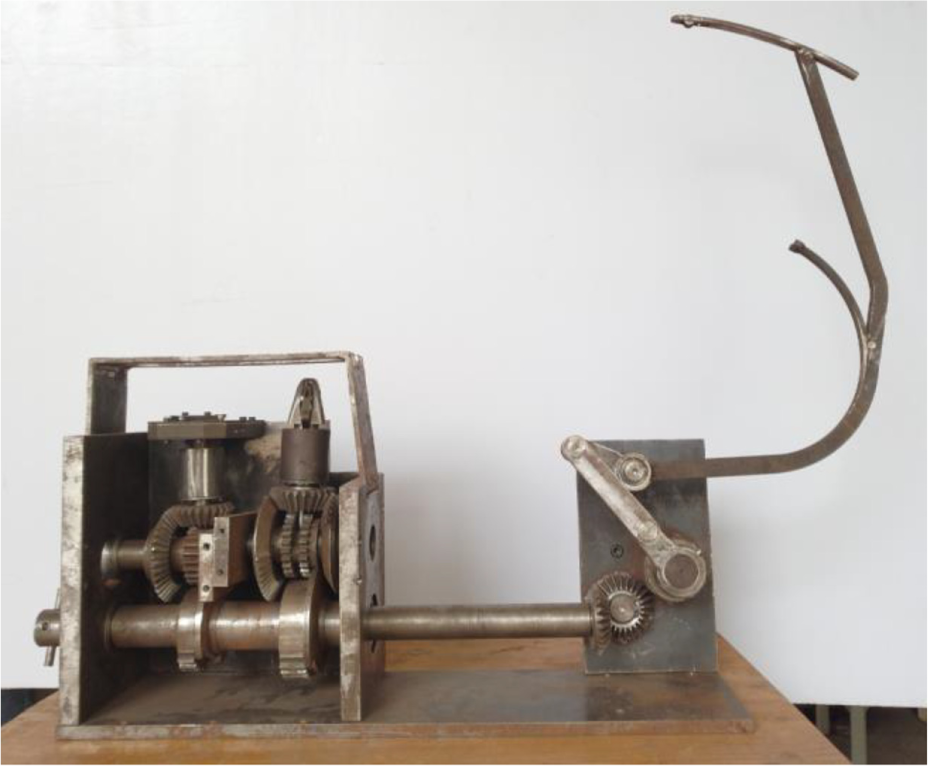
The Mock-up of knotter.
The knotter spindle is driven manually, the knotter’s driven system and knotting effect are verified. A total of 500 tests were conducted and of which, 492 tests met the knotting requirements. The knot effect is shown in Figure 29, and the knotting process is shown in Figure 30.
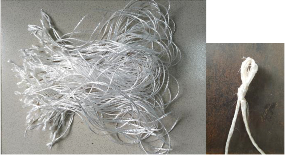
The knotted knot.

Knotting process: (a) The knotting hook was in the original state, (b) The knotting hook rotated 170°, (c) The rope wound rounded the knotting hook, (d) The rope was gripped by the movable jaw, (e) The knot began to turn back, (f) The rope was cut, (g) The knotting hook was returned to its original position and (h) The rope buckle was taken off.
Conclusion
A method of knotted rope is presented which is proved to be reliable and effective by experiments.
According to the principle of proposed knotting method, the design consisted of a rope feeding mechanism, a rope clamping mechanism, a rope hooking and griping mechanism and the driven system. They can be realized by sending rope, clamping rope, hooking and gripping rope, cutting rope, tripping out of the rope buckle, and so on. The individual operation of all actions can be in place and coordination of all actions are coordinated. Moreover, the matching motion cycle diagram is proved to be reasonable.
The new incomplete gear mechanism solves the problem that in the conventional incomplete gear mechanism, the driven gear can swing at a large angle or even cannot be locked in the case when the locking arc of the passive gear is too short.
A total of 500 knotting tests were performed on the physical model of knotter with the success rate of 98.4%. The experiment proved the reliability and stability of designed knotter.
Compared with the traditional knotter, the new knotter has no separate mechanism for cutting rope and tripping out of the rope buckle, which simplifies the structure and reduces the difficulty of design and manufacture.
Footnotes
Handling Editor: António Mendes Lopes
Declaration of conflicting interests
The author(s) declared no potential conflicts of interest with respect to the research, authorship, and/or publication of this article.
Funding
The author(s) disclosed receipt of the following financial support for the research, authorship, and/or publication of this article: This work was supported by the Guangxi Science and Technology Development Plan of China (No. AB16380235). We thank our colleagues who provided insight and expertise that greatly assisted the research.