
Abstract
There are many problems and physical phenomena in turning process, like machined surface quality, cutting force, tool wear, and so on. These factors and the chip shape of workpiece materials, which is an important aspect to study the mechanism of ultrasonic vibration–assisted turning, go hand in hand. This article first introduces the types and changes of chip, meanwhile the chip formation mechanism of ultrasonic vibration–assisted turning is studied and analyzed, and the turning experiments of 304 austenitic stainless steel with and without ultrasonic vibration are carried out. The difference of chip morphology between ultrasonic vibration–assisted turning and conventional turning is contrasted and analyzed from the macroscopic and microscopic point of view. The influence of process parameters on chip shape and the impact of chip shape on machining effect are also analyzed. Results indicate that when process parameters (vibration frequency, ultrasonic amplitude, and cutting parameters) are suitably selected, ultrasonic vibration–assisted turning can gain access to better chip shape and chip breaking effect than conventional turning. By contrast with conventional turning, phenomenon of serrated burr on the chip edge and the surface defects of chip in ultrasonic vibration–assisted turning have improved significantly. Moreover, it is found that superior chip morphology in ultrasonic vibration–assisted turning can be acquired under the circumstance of comparatively small cutting parameters (cutting speed, depth of cut, and feed rate); at the same time, preferable chips can also obtain ranking machining effect.
Introduction
Considering from the machining quality, removed metal amount, productivity, and capacity utilization, the turning has a wide range of application nonetheless, and it is an economical and practical way of machining.1–3 However, along with extensive use of various precision instruments and components, there is an increasing demand for the machining precision and processing quality. 4 Meanwhile, various difficult-to-cut materials have gained widespread application, and the quantity of turning processing has been increased in the mechanical manufacturing,5,6 which enable the difficulty of turning processing to be enhanced unceasingly. For the conventional turning (CT) technic, on account of being accompanied by the problems containing chip removal difficulties, big cutting force, and serious tool wear in the cutting process, which can bring out worse machining quality, lower machining efficiency, and higher cost of machining. CT includes great limitations; nevertheless, the ultrasonic vibration–assisted turning (UAT), which is a typical special processing method, has provided an effective approach for high-quality and high-efficiency processing of difficult-to-cut materials.7–12
In UAT, through high-frequency and small-amplitude machining, not only the normal machining of parts is ensured but also workpiece material deformation does not happen because of extremely short contact time. Due to introduction of ultrasonic vibration in UAT, the material removal mechanism of CT is changed. The material removal is carried out principally through the action of mechanical cutting and high-frequency micro-impact, and the machining effect can be achieved, which is difficult to be acquired in CT. In contrast with CT, UAT can improve dynamic cutting stability;9,10 lower surface roughness,13,14 cutting force,15,16 and temperature;17,18 and reduce tool wear19,20 and residual stress of machined workpiece. 21 After adopting ultrasonic vibration, turning process has been immensely improved, and excellent process effect has been diffusely concerned.9–21
The 304 austenitic stainless steel, which is a representative difficult-to-cut material, has a wide range of applications and a large amount of usage, but it is difficult to machine, and its mechanical machining property is more difficult than other alloy steels.1,22 Hence, it is very meaningful to implement high-quality and high-efficient machining on 304 austenitic stainless steel, and the problem of difficult machining is figured out commendably using UAT. But in the existing literature works and visible documents, there are not lots of correlative studies on UAT of 304 austenitic stainless steel, especially analysis from the perspective of chip shape is not consummate until now. Mahdy et al. 23 made a comparative test on 304 austenitic stainless steel of UAT and CT, and the research found that UAT could reduce the average surface roughness, as well as the tangential and radial components of cutting force compared with CT. Vivekananda et al.5,24 made use of the finite element method to design and analyze ultrasonic vibratory tool, and studied the difference of turning 304 austenitic stainless steel with and without ultrasonic vibration; the results indicated that UAT could reduce the cutting force and surface roughness.
Analyzing the chip deformation rule and the chip macromorphology and micromorphology is of great significance to go into the mechanism of tool wear and enhance machining quality and efficiency of difficult-to-cut materials in UAT, which contributes to obtain desired machining effect. The ultrasonic vibration system is installed on the general machine tool in this research to meet the requirement of the ultrasonic vibration cutting in the actual production. In addition, a widely used and typical difficult-to-cut material is applied to the experimental research, and the machining effect of UAT is analyzed particularly in terms of chip shape. The investigation will provide theoretical support and experimental basis for the progress and application of the UAT of difficult-to-cut materials.
Morphology and formation of chips in UAT
Types and variation of chips
Due to diverse workpiece materials, cutting conditions, and deformation of the cutting process, different chip types are generated, mainly including four types: ribbon chip, segmental chip (shearing chip), granular chip (unit chip), and cracking chip, as illustrated in Table 1. In addition, according to characteristics of chip deformation, chip also fall into two categories: continuous chip and discontinuous chip. This has something to do with the property of the workpiece material itself, chiefly. In general, it is effortless to produce continuous chips with the appropriate plasticity, and poor plasticity tends to produce discontinuous chips.
Main types of chips.

In the above four chip types, the cutting process of ribbon chip is smoothest, the fluctuation of cutting force is relatively small, and the machined surface is also brighter and cleaner, but continuous ribbon chips easily twine on workpiece, so breaking chips should be tried to proceed. The cutting process of segmental chip is not so smooth, the cutting force fluctuates, and the surface roughness is larger. The cutting process of granular chip is unstable, the fluctuation of cutting force is larger, and the machined surface is rougher. The cutting heat and cutting force of cracking chip are concentrated near the main cutting edge and tool nose, resulting in impact, tool broken and poor surface quality. Moreover, certain chips also have common characteristics of two or more chip types mentioned above.
In production practice, chips of different shapes are generally produced, the common shapes of which are spiral coil chip, long and tight coil chip, ribbon chip, hair strips coil chip, pagoda-like coil chip, cracking chip, and C-shape chip, as shown in Figure 1. This is primarily associated with the workpiece material, tool geometric, and cutting parameters. On the different cutting conditions, the disparate anticipative chip shapes are obtained. During finish machining, spiral coil chip is more anticipated, the shape of chips will break off automatically if they reach a certain length, and cutting process is relatively stable. In cutting, cracking chip is least expected to gain, the next is C-shape chip.
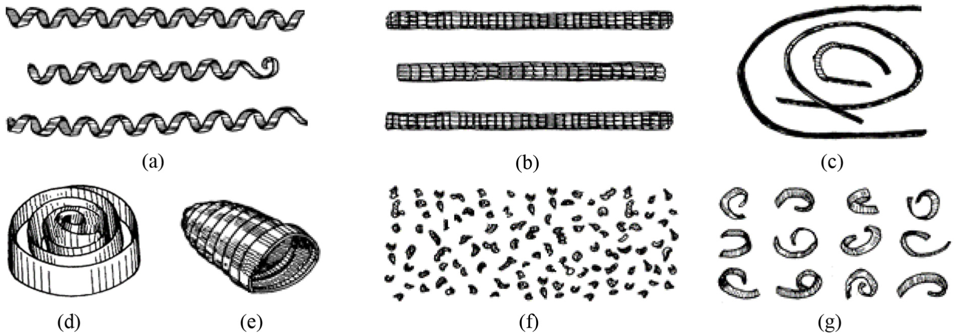
Common chip shapes: (a) spiral coil chip, (b) long and tight coil chip, (c) ribbon chip, (d) hair strips coil chip, (e) pagoda-like coil chip, (f) cracking chip, and (g) C-shape chip.
Chip formation mechanism in UAT
In fact, the turning process is the process in which the material is removed to form chips. Chip formation process is one of the most crucial characteristics of UAT. Various physical phenomena in UAT (cutting force, tool wear, and metal softening) are inseparable with chip formation process. The friction in turning can also be reflected from the chip shape; moreover, the formation of chips also affects surface quality, machining accuracy, and so on.
In brief, the workpiece material deforms elastically under the action of cutting force, and plastic deformation takes place when pressure varies continuously up to the limit of yielding; the material is cracked and flows out along the rake face to become chips when the fracture strength is reached. In UAT, the chip formation process is essential course of extrusion, vibration, and shearing. In this course, cutting tool cuts material of definite size on the workpiece in the form of pulses to make it produce shear deformation regularly and generate chips; the chips are also cut off by cutting tool with little hindrance in the vibration. The chip formation process of UAT is shown in Figure 2.

Chip formation process in UAT: (a) contact, (b) separation, and (c) chip formation. 25
During UAT, chips are formed principally by means of pulse directional slip. In UAT, the high-frequency and low-amplitude ultrasonic vibration is brought in to make cutting tool have a percussive action in cutting. The percussive action is equivalent to a peak of thermal vibration, which can soften the material before the cutting edge of cutting tool and lower the fracture threshold as well. Utilizing the principle of fracture dynamics, for a point in front of the workpiece crack corresponding to the tool tip in cutting area, the stress wave velocity due to cutting tool impact is much higher than the cutting tool motion velocity. Beneath the affect of dynamic stress intensity factor, when cutting tool has not moved to this point, the internal stress has reached the strength limit to make the material fracture, that is, the phenomenon of cracking has been formed at this point. Just then, as long as a lesser force continues to act on the crack initiation zone, the propagation of cracks can be implemented. Therefore, when cutting tool moves to this position, the turning can be achieved with less cutting force, and this is the chip removal mechanism of UAT.
The cutting force which plays a main role in the formation of chips in UAT is generated by the vibration system, it is not provided by the main motor of machine tool, and the workpiece only moves in a circle. According to the regular pulse force, turning is proceeded by the cutting tool during machining. In addition to the normal cutting motion and applied ultrasonic vibration, there is no additional relative motion between cutting tool and workpiece, so the width and thickness of chips are without marked variation. Chips can be nearly acquired by all the common materials in UAT, which are similar to the parent material, are no producing heat, and have smooth surface without obvious burr.
Experimental conditions and procedures
Workpiece and cutting tool
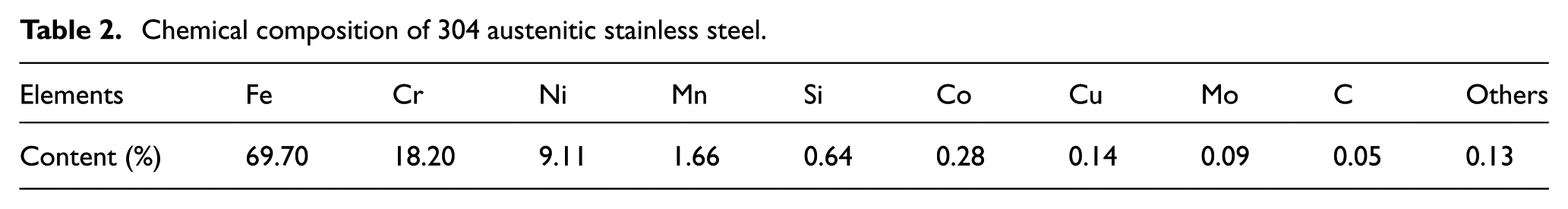
In experiments, 0Cr18Ni9 (i.e. 304 austenitic stainless steel) was singled out as the workpiece material. The 304 austenitic stainless steel, which belonged to a type of difficult-to-cut material, was a broadly applied chromium (Cr) nickel (Ni) stainless steel. Cr increased the bonding tendency between material and cutting tool; Ni was prone to give rise to large plastic deformation of the material, bringing about work hardening; and the chemical composition is listed in Table 2. The 304 austenitic stainless steel had good mechanical properties, low temperature strength, corrosion resistance, and heat resistance; physical and mechanical properties made a great difference in the characteristics of cutting process, and the physical and mechanical properties are listed in Table 3.
Chemical composition of 304 austenitic stainless steel.
Physical and mechanical properties of 304 austenitic stainless steel.

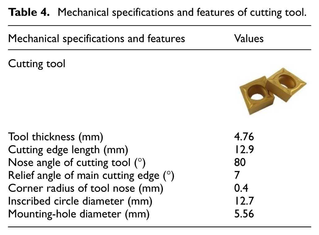
The difficulty of turning 304 austenitic stainless steel lies in large cutting force, severe work hardening, difficult chip breakage, and quick tool wear during cutting. In order to fulfill the high-quality and high-efficiency machining of 304 austenitic stainless steel, it was necessary to pick out the cutting tool with good abrasion resistance and thermal hardness, sharp cutting edge, anti-bonding rake face, smooth chip removal, and small surface roughness. Moreover, in the light of the above factors, CCMT120404-HM YBM251–type cutting tool, which is a cemented carbide-coated cutting tool, was selected in experiments. The coating material on the cutting tool surface was TiC-Al2O3-TiN. The geometric parameters of cutting tool had much affect on the machining effect and tool life, and the mechanical specifications and features of CCMT120404-HM YBM251–type cutting tool are listed in Table 4.
Mechanical specifications and features of cutting tool.
Experimental setup
Aimed at the machining system of UAT, the portion of implementing ultrasonic machining was principally composed of the machine tool, ultrasonic generator, ultrasonic transducer, ultrasonic horn, tool system, and special fixture. In machining, the lathe host and machine tool control system were applied to achieve the rotation and feed motion required by turning, and UAT was accomplished via combining with the ultrasonic vibration produced by ultrasonic vibration system. The structure diagram of ultrasonic vibration system is demonstrated in Figure 3(a).

Experimental setup: (a) structure diagram of ultrasonic vibration system, (b) photograph of machining system of UAT, and (c) VHX-1000E–type super depth-of-field 3D display system.
In this study, the machining system of UAT, which was designed by us and built on the basis of a CA6140 type general lathe, was used for experiment. Commencing from the cutting principle and machining technic and adopting the method of ultrasonic vibration, ultrasonic vibration was applied to the cutting tool, and the general lathe was transformed into machining system of UAT. Figure 3(b) displays the photograph of machining system of UAT.
The machined chip morphology was measured by the VHX-1000E–type super depth-of-field three-dimensional (3D) display system, as demonstrated in Figure 3(c). The VHX-1000E–type super depth-of-field 3D display system had 20–200 times low-power zoom lens and 500–5000 times high-power zoom lens, which could easily and quickly analyze the microscope scene, simultaneously fulfill super depth-of-field 3D measurement, and obtain the micromorphology of the machined chips rapidly.
Experimental details
Chip shape is a momentous embodiment of deformation process and mechanism, and different chip shapes have the disparate deformation processes and mechanisms. For the sake of contrasting and analyzing the difference of chip shape between UAT and CT, using designed machining system of UAT, the turning experiments of 304 austenitic stainless steel—with and without ultrasonic vibration—were carried out in dry condition.
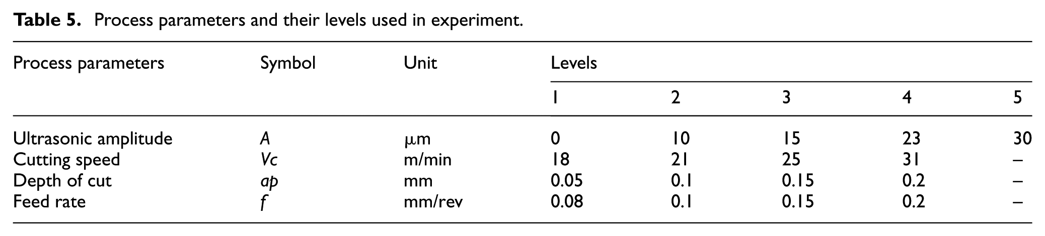
In this research, the vibration frequency was fixed at 20 kHz, and other process parameters and their levels used in experiment are listed in Table 5. Thereinto, vibration frequency and ultrasonic amplitude were implemented by ultrasonic generator, and cutting speed, depth of cut and feed rate were realized by machine tool. The 2000BDC-type ultrasonic generator could output the electrical oscillation signal with the frequency of 20 kHz stably and enforce the ultrasonic amplitude adjustment in the range of 10–100 µm. In this study, the ultrasonic amplitude value, which could be performed stably by the machining system, was selected for the experiment. UAT was more appropriate for semi-finishing and finishing, so the cutting parameters should not be too large, especially the cutting speed; if the excessive cutting speed was chosen, the separation action of workpiece and cutting tool, produced by ultrasonic vibration, would be weakened, leading to the process of UAT drawing near to CT. Therefore, comparatively, small cutting speed, depth of cut, and feed rate were selected in this research.
Process parameters and their levels used in experiment.
Experimental results and discussion
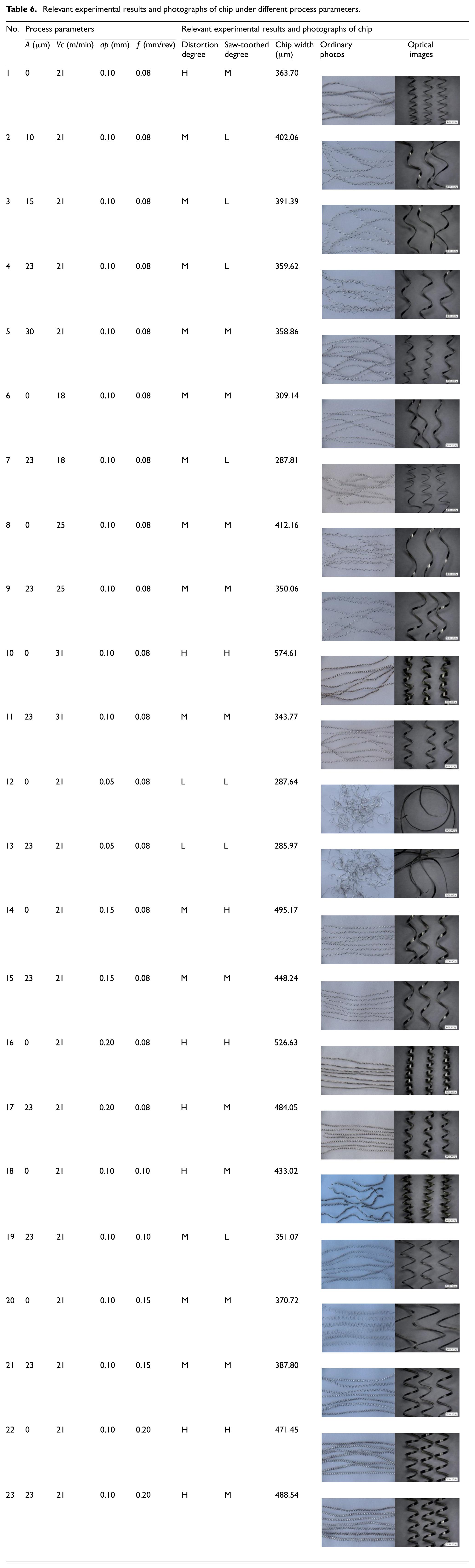
During the experiment process, the chips were collected under different process parameters, and photographs were taken by a camera and super depth-of-field 3D display system. In the meanwhile, the distortion degree and saw-toothed degree of chips and the values of chip width under different process parameters were also obtained. Relevant experimental results and photographs of the chip acquired under the corresponding process parameter are listed in Table 6. The capital letters H, M, and L represent high, middle, and low, respectively.
Relevant experimental results and photographs of chip under different process parameters.
In the process of metal cutting, chip deformation is an objective phenomenon, which can directly affect the chip flow direction, chip curling, and chip breaking. Different chip deformation forms make different formations and breaking manners. Under 3D chip deformation (namely, transverse curl), the chip width is one of the crucial parameters of chip formation and chip breaking, which has an important impact on chip deformation. When one side is a free surface along cutting width during cutting, transverse expansion is generated, including transverse flow and transverse deformation of the chip under the extrusion of rake face, and chip width alters. Due to the difference of outflow velocity between the internal and external sides of the chip, the chip transverse curl occurs. Therefore, the change of chip width directly influences the chip flow direction, chip curling, and chip breaking of 3D deformation. Although there is no significant difference between the chip width of UAT and CT, it is necessary to investigate the change of chip width. Histogram of chip width changed with process parameters can be achieved by means of relevant experimental results, as shown in Figure 4.
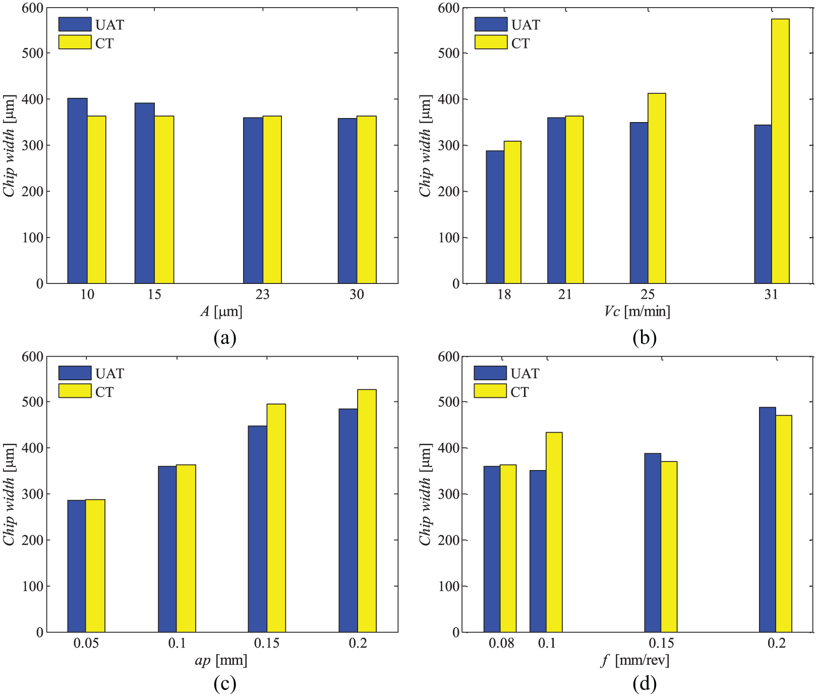
Histogram of chip width changed with process parameters: (a) changed with ultrasonic amplitude, (b) changed with cutting speed, (c) changed with depth of cut, and (d) changed with feed rate.
For thorough research into the chip shape in UAT, the several essential groups of chips under the representative process parameters are selected in Table 6; furthermore, comparative analysis is conducted from the angle of chip macromorphology and micromorphology by combining distortion degree and saw-toothed degree with chip width.
Comparative chips macromorphology analysis
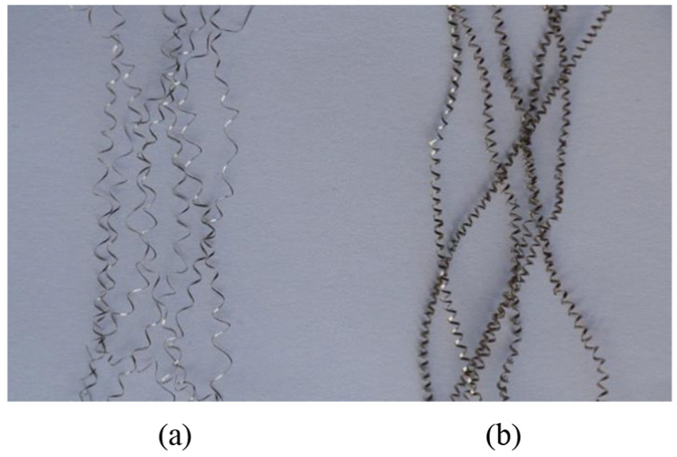
The following cutting conditions are used in the analysis: Vc = 21 m/min, ap = 0.1 mm, ƒ = 0.08 mm/rev, and A = 23 μm or A = 0 (CT). And, with that support, the chip photos of UAT and CT are shown in Figure 5. As can be seen from the figure, the chips obtained with and without ultrasonic vibration all belong to spiral coil chips, but the difference is obvious. The chips of UAT take the shape of loose spiral coil, the curling radius is relatively larger, and the distortion is relatively smaller, it is also lighter in actual cutting. The chip curling degree of CT is enhanced and has a certain degree of toughness, and chip breaking has not easily taken place as well. However, as can be seen from Figure 4(a), what is with and without ultrasonic vibration has no obvious effect on chip width under this cutting condition; nevertheless, the chip width in UAT has a gradually decreasing tendency with increase in ultrasonic amplitude. This is mainly due to the fact that turning is conducted by cutting tool in accordance with the regular pulse force in the UAT process. And, there is no relative movement between the cutting tool and the workpiece except cutting movement and ultrasonic vibration.

Chips at Vc = 21 m/min, ap = 0.1 mm, f = 0.08 mm/rev: (a) UAT and (b) CT.
Other conditions remain unchanged, the cutting speed is increased to 31 m/min in comparison to Figure 5, and the chip photographs as shown in Figure 6 are obtained. Compared with the chips with and without ultrasonic vibration in Figure 6, it can be discovered that the chip deformation of UAT is less than that of CT. This is mainly because the ultrasonic vibration can weaken the extrusion effect of the negative chamfering of cutting tool on the tool edge during processing, which will reduce the chip deformation rate. According to Figures 4(b), 5, and 6, it can be easily seen that when the cutting speed increases, there is no significant change in the chips of UAT, while the chip width and distortion degree of CT increase at different levels, especially the change of chip width is quite obvious. It is further illustrated that the cutting speed has little effect on the chip width of UAT, while it has a relatively large influence on the chip width of CT, and the chip width increases greatly with the increase in cutting speed, which is related to the influence of cutting speed on cutting force.
Chips when cutting speed is increased: (a) UAT and (b) CT.
In contrast with Figure 5, other process parameters remain the same, the depth of cut is increased to 0.2 mm, and the chip photos as shown in Figure 7 are gained. On comparison with Figure 4(c), it is not difficult to see that when depth of cut increases, the chips with and without ultrasonic vibration all change obviously, and the chip width increase to a certain extent. As the depth of cut increases, the part involved in cutting of main cutting edge lengthens accordingly; therefore, the chip width in both UAT and CT gradually increases with the increase in depth of cut. And, on the whole, the chip width of UAT is slightly smaller than that of CT. Moreover, the degree of chip curling deformation also increases significantly. This is because the chips on a small cutting area bear a large unit cutting force, and the increase in the depth of cut results in the increased deformation of the chip under extreme extrusion pressure. However, the chip deformation degree of UAT in Figure 7 is obviously smaller than that of CT, and it also proves that UAT gains smaller cutting force.

Chips when depth of cut is increased: (a) UAT and (b) CT.
In contrast with Figure 5, other conditions remain the same, the increased feed rate is 0.2 mm/rev, and the chip photos as shown in Figure 8 are acquired. It can be seen from the comparison between Figures 5 and 8 that when the feed rate increases, the chips of UAT and CT also change greatly. The degree of chip curling deformation and curling radius are much larger than that under lower feed rate. In addition, as shown in Figure 8, the chips are similar with and without ultrasonic vibration, they are all spiral coil chip, and the curling radius and curling degree are of varying sizes. However, the chip breaking effect of UAT is better than that of CT due to the assistance of ultrasonic vibration in the actual machining tests, whereas from Figure 4(d), it is evident that there is no specific rule of the influence of feed rate on chip width. This is mainly because all the depth-of-cut values selected in this study are smaller than the corner radius of tool nose, and the circular arc part of main cutting edge participates in cutting principally, while—theoretically—the increase in feed rate impacts the part involved in cutting of tool minor cutting edge. Although the chip width does not change regularly with the increase in feed rate, the chip width also tends to increase gradually with the increase in feed rate. The reason lies in that when the feed rate increases, chip thickness also increases, and the chip transverse flow capacity is enhanced, hence the chip width increases.

Chips when feed rate is increased: (a) UAT and (b) CT.
Through the analysis of the above, it can also be found that under the condition of individual process parameters, chip width and distortion degree in UAT are slightly larger than that of CT, but the variation is not so big as to affect machining effect. However, it is also important to choose process parameters. As a result, the reasonable process parameters must be chosen in the actual machining, which is substantially beneficial to achieve higher quality and considerable productive machining effect.
Comparative chips micromorphology analysis
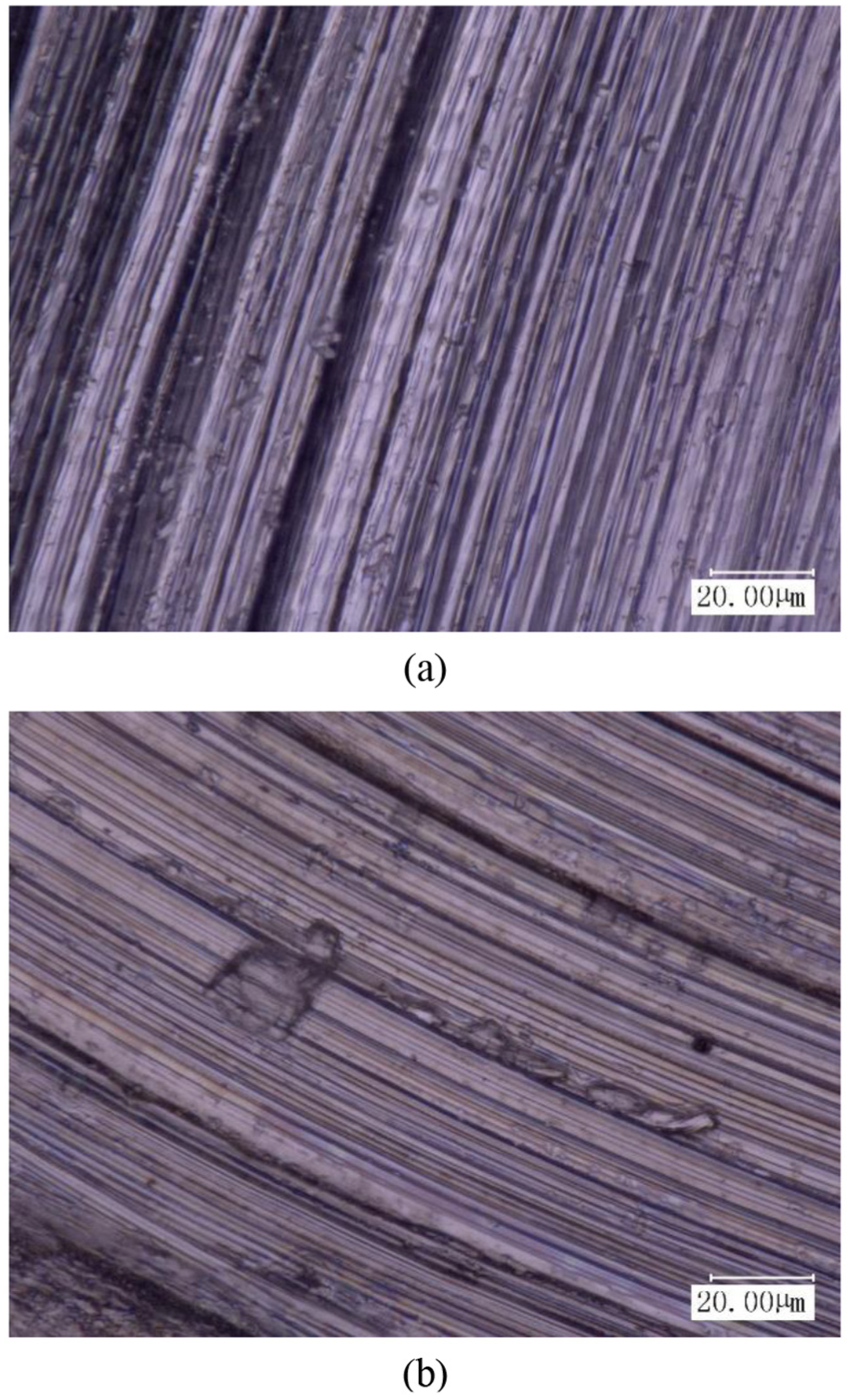
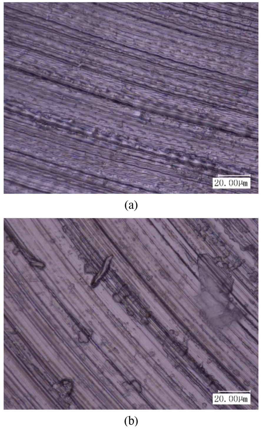
The following process parameters are used in the analysis: Vc = 21 m/min, ap = 0.1 mm, ƒ = 0.08 mm/rev, and A = 23 μm or A = 0 (CT). As shown in Figures 9 and 10, the super depth-of-field optical images of the chips in UAT and CT are amplified by 500 times and 2000 times. From the figures, it is observed that many sawteeth of different sizes and shapes took shape on the chip edges of CT. Not only that, the chip surface is also very rough, and there are some defects such as scratches, collapse, deep pits, and bulges on it. In spite of sawteeth being on the chip edges of UAT, they are contrarily small and smooth. Sawtooth edges show up as arc shape, and there is no remarkable difference between sawteeth, which are uniformly distributed. Furthermore, the chip surface has no obvious defects, meanwhile the regular vibration marks aroused by the ultrasonic vibration are formed, and the surface looks relatively smooth and delicate.
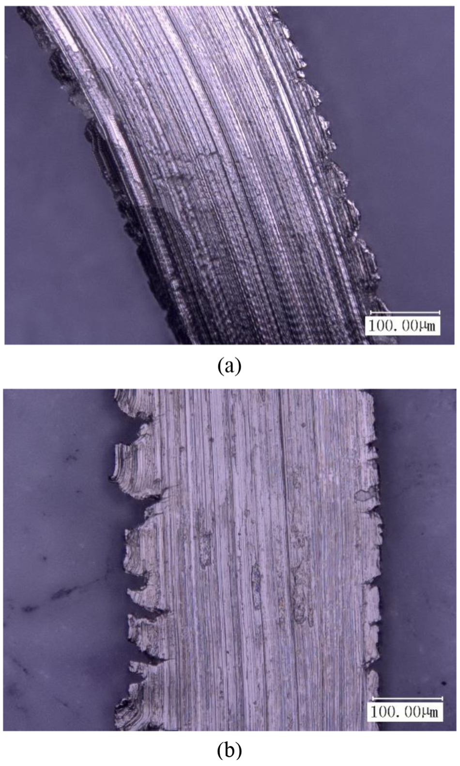
Chip morphology magnified 500 times: (a) UAT and (b) CT.

Chip surface magnified 2000 times: (a) UAT and (b) CT.
Increasing the cutting speed to 31 m/min, under the depth of cut of 0.1 mm, and feed rate of 0.08 mm/rev, the super depth-of-field optical images of the chips magnified by 500 and 2000 times are obtained as shown in Figures 11 and 12. It can be seen that when the cutting speed increases, the saw-toothed degree of chips in UAT and CT has also risen in varying degrees. In particular CT, burrs arise on the edges of both sides of the chips, and adhesive materials appear. Furthermore, gouges and defects on the chip surface also become more apparent, but for the most part, the chip saw-toothed degree and surface defects of UAT are much smaller than that of CT. When the cutting speed is lower, the chip has smaller internal strain and strain rate, and the chip deformation is carried out in the manner of uniform slip. With the increase in cutting speed, the internal strain and strain rate of the chip also increase to rise the temperature in the main shear zone rapidly and to intensify the thermal softening. As a consequence, the shear resistance declines sharply and the bearing capacity of material weakens. Adiabatic shear fracture is conducted periodically by the chips along the main shear zone, resulting in jagged chips with more severe deformation. 26

Chip morphology magnified 500 times when cutting speed is increased: (a) UAT and (b) CT.
Chip surface magnified 2000 times when cutting speed is increased: (a) UAT and (b) CT.
Under the depth of cut of 0.2 mm, cutting speed of 21 m/min, and feed rate of 0.08 mm/rev, as shown in Figures 13 and 14, the super depth-of-field optical images of the chips in UAT and CT are amplified by 500 times and 2000 times. Compared with Figures 9 and 10, it can be found that the increase in depth of cut has little effect on the chip saw-toothed degree and surface topography of UAT and CT, and only numerous burrs appear on the other side of chip edge. Moreover, from the chip surface morphology, the surface vibration mark of UAT becomes clearer, defects such as built-up edge debris and adhesive materials are increased on the chip surface of CT. Compared with the chips with and without ultrasonic vibration under the depth of cut of 0.2 mm, it can be seen that there are irregular serrated burrs on the chip edge belt of CT, and surface defects are correspondingly more. Capitalizing on ultrasonic vibration, the phenomenon of serrated burr on chip edge significantly shortened, the surface in contact with cutting tool is more smooth and flat. It is further indicated that the turning process is smoother, the friction coefficient is smaller, and the chip removal is smoother, hence the preferable cutting effect can be chalked up.

Chip morphology magnified 500 times when depth of cut is increased: (a) UAT and (b) CT.
Chip surface magnified 2000 times when depth of cut is increased: (a) UAT and (b) CT.
Increasing the feed rate to 0.2 mm/rev, under the cutting speed of 21 m/min, and depth of cut of 0.1 mm, the super depth-of-field optical images of the chips magnified by 500 and 2000 times are obtained as shown in Figures 15 and 16. Compared with the chip micromorphology of feed rate of 0.08 and 0.2 mm/rev, it can be clearly seen that the chip micromorphology changes significantly with and without ultrasonic vibration when the feed rate increases. The serrated chips of UAT from circular arc turn into sawteeth, which are analogous to CT, but it is obviously less than chip saw-toothed degree of CT, and on some places, sawteeth do not take shape entirely yet, which maintain in smooth condition. Deep scratches appear on the chip surface of CT, on which distinct deep pit, built-up edge debris, and adhesive materials also appear. This is primarily due to the increase in extrusion effect in the frontal area of cutting edge with the feed rate increasing, bringing out the increase in friction between chip and chip, chip and cutting tool, chip and workpiece material. At the same time, the chip deformation rate increases to make gross defects be produced on the chip surface, but the impact on UAT is relatively small.

Chip morphology magnified 500 times when feed rate is increased: (a) UAT and (b) CT.

Chip surface magnified 2000 times when feed rate is increased: (a) UAT and (b) CT.
Influence of chip shape on machining effect
Due to strong plasticity of 304 austenitic stainless steel, most of the chips obtained in processing are continuous spiral coil chips, and this can be also seen from the chip images in Table 6. In the turning process, chips should be guaranteed to break after a definite length being reached. If chip breaking does not go smoothly, the longer chips will twine around the workpiece or cutting tool, which is effortless to scratch the machined surface or to damage the cutting edge of cutting tool. This will not only affect the machined surface quality and reduce productivity but also damage the accuracy of machine tool, and even influence the safety of operator.
After severe deformation in the first deformation zone and the second deformation zone, the hardness of chips increases, the plasticity of chips decreases, and the chips become brittle as well. Therefore, when the chips encounter barriers such as the flank face of cutting tool, the transitional surface or work surface of workpiece in the course of discharge, and if the strain value at a certain position on the chip exceeds the fracture strain value of chip material, chips will break off automatically, as shown in Figure 17. In UAT, on account of the auxiliary role of ultrasonic vibration, chip is more toilless to reach the strain value which makes it fracture, and in consequence, the effect of chip breaking is particularly outstanding. It is also discovered in tests that when the length of chips reaches certain value, they are more effortless to break off than that of CT, which is one of the reasons that the machined surface quality and tool wear of UAT are better than that of CT.

Reasons for the chip breaking: (a) result from crashing into cutting tool and (b) result from crashing into workpiece.
In the process of chip formation, larger elastic–plastic deformation of workpiece materials takes place under the squeezing action. In the first deformation zone, shear slip of the materials of cutting layer is performed along the shear plane. The stress of chips on the shear slip plane increases with work hardening. When the local material reaches ultimate strength, in the second deformation zone, extrusion and friction are conducted sequentially along the rake face of cutting tool to crack chip top; nonetheless, the chip bottom still connects with workpiece. Therefore, the chip edge in contact with the rake face of cutting tool is considerably smooth; on the other side of chip edge, serrated burrs are easy to be generated under the action of cutting force.
Comparing the experimental analysis of the macromorphology and micromorphology of chips, it can be found that different degrees of deformation and sawteeth of the chips in UAT and CT are generated. However, under the same cutting conditions, the chip deformation and saw-toothed degree of UAT are far less than that of CT, and the chip surface morphology is also significantly better than that of CT. The chips generated by the CT with serrated burrs and many surface defects are extremely detrimental to the high-quality machining, which gives rise to uneven friction in the cutting area, which results in high temperature, large cutting force, high regenerative chatter, and fast tool wear.11,19 On the contrary, owing to intermittent role between cutting tool and workpiece, chips are generated in UAT, which edges are relatively slick and surface defects are less. The above negative phenomena which are facile to occur in CT are obviously improved in UAT.
In addition, the formation of serrated chip can give rise to the high-frequency fluctuation of cutting force lightly, resulting in the fluctuation of cutting tool and workpiece. The change has a certain influence on the formation of machined surface topography, peculiarly on the surface roughness of the machined workpiece. 25 During turning, when serrated chips are produced, the strain and strain rate increase to lead to tear phenomenon on the workpiece separation surface with material deformation. In the process of forming serrated chips, the deformation of workpiece material changes periodically and also has periodic influence on the boundary wear of cutting tool. It is facile to shape into uneven scratches on the machined surface when the microcrack phenomenon emerges in the tool tip, which affects the surface roughness of the machined workpiece and the usability of the machined parts. Besides, the chip formation process of UAT is more reliable than that of CT, and the chip shape obtained is also much more inerratic than that of CT. And, chip shape can reflect the good or bad quality of machined surface, so UAT of 304 austenitic stainless steel can get more superior machined surface quality than CT.
The workpiece surface is readily scratched by the chips with serrated burrs in CT; therefore, the surface quality of the machined workpiece is damaged. UAT can well inhibit the generation of serrated burrs on the chip edge, and more perfect machined surface can be acquired. Moreover, the sawteeth formed on the chip edge constantly impacts and scratches the cutting edge and rake face of cutting tool. On account of high formation rate of serrated chips, this high-frequency impact load forms stress and temperature shock on the rake face of cutting tool to make the cutting tool produce microcracks with a wet finger. 27 Under the influence of continuous impact load, the microcracks will keep on developing, which induces tool wear in a breeze, even damaged phenomena may come out. 28 UAT can cut down or even eliminate the harmful vibration produced by the machining system of CT, which also can weaken surface friction, meanwhile the turning process is smooth, so that during machining material does not reach the extent of damage and the spiral coil chips are formed with smooth edges and less surface defects.
Conclusion
This article presents an experimental study on chip shape in UAT of 304 austenitic stainless steel. The following conclusions can be drawn from this work:
The distortion degree of chip produced in CT is larger, and many serrated burrs of various sizes and shapes are formed on the chip edge. And, the chip surface is particularly rough, on which there are some defects such as scratches, collapse, deep pits, and bulges. The machined surface quality, cutting force, and tool wear have seen varying degrees of impact.
The chips produced in UAT contribute to obtaining the superior machining effect; the generated chip is principally loose spiral coil chip, which is of relatively smaller distortion and the larger curling radius; and the chip breaking effect is comparatively ideal. And, the phenomenon of serrated burrs on the chip edge is improved obviously, and there are no conspicuous defects on the chip surface; at the same time, the regular vibration marks aroused by ultrasonic vibration are formed, and the surface is correspondingly smooth and delicate.
In UAT, selecting appropriate process parameters is crucial to come into being preeminent chips. The cutting parameters have a significant impact on chip shape. With the increase in cutting speed, depth of cut, and feed rate, the distortion degree of chip, the saw-toothed degree of chip edge, and the surface defects of chip are all increased in varying degrees. A more remarkable chip morphology can be acquired without a hitch under small cutting parameters contrarily, and the preferable chips can bring out better machining effect.
Footnotes
Handling Editor: Jianfu Zhang
Declaration of conflicting interests
The author(s) declared no potential conflicts of interest with respect to the research, authorship, and/or publication of this article.
Funding
The author(s) disclosed receipt of the following financial support for the research, authorship, and/or publication of this article: This study received financial support from the Doctoral Scientific Research Foundation of East China University of Technology (No. DHBK2016113).