
Abstract
With excellent properties, high-temperature superalloys have become the main application materials for aircraft engines, gas turbines, and many other devices. However, superalloys are typically difficult to machine, especially for the thread cutting. In this article, an ultrasonic vibration–assisted turning system is proposed for thread cutting operations in superalloys. A theoretical analysis of ultrasonic vibration–assisted thread cutting is carried out. An ultrasonic vibration–assisted system was integrated into a standard lathe to demonstrate thread turning in Inconel 718 superalloy. The influence of ultrasonic vibration–assisted machining on workpiece surface quality, chip shape, and tool wear was analyzed. The relationship between machining parameters and ultrasonic vibration–assisted processing performance was also explored. By analyzing the motion relationship between tool path and workpiece surface, the reasons for improved workpiece surface quality by ultrasonic vibration–assisted machining were explained.
Keywords
Introduction
For the past several decades, high-temperature alloys were widely used. With ever-increasing industry demand, various kinds of high-temperature alloy materials with superior performance are constantly emerging. Inconel 718 nickel-based high-temperature alloy is one of the promising materials, which was discovered in the 1960s and was widely used in the production of military aircraft engine parts by GE and P&W companies.1,2 After more than half a century of development, this material has become a main application material for aero-engines and is also widely used in gas turbine, navigation, and nuclear power industries. Under severe conditions, such as high temperatures and strong acids, it can still bear large forces and retain excellent fatigue resistance, plastic performance, high yield strength and oxidation resistance. 3 The excellent performance of nickel-based high-temperature alloys not only provides convenience for various industries, but also introduces difficulties in their manufacture. Its machining difficulties mainly include high cutting resistance, high cutting temperature, severe machining hardening, severe tool wear, and low machining efficiency.4,5 In the machining process, due to the high cutting resistance and high cutting temperatures, the plastic deformation of the workpiece surface is significant, which is accompanied with fierce machining chatter. With the increase in the cutting speed, plastic deformation and chatter will also become more severe, which will markedly affect the machining quality. In this deformation process, a stable surface strengthening layer is also generated. This will, in turn, increase the processing difficulties in subsequent processes and speed up tool wear. Meanwhile, with the development of aeronautics and astronautics, the processing quantity of aviation components is increasing, and the difficulties in processing such material lead to much lower processing efficiencies, which are needed to improve and promote new developments in the aerospace industry and related fields.
Ultrasonic vibration–assisted cutting (UVAC) is a processing method in which high-frequency ultrasonic vibrations (UVs) are applied to the cutting tool or workpiece. Such vibrations change the contact mode and motion between the tool and the workpiece leading to better processing performance. The UV frequency is generally higher than 16 kHz, and these high-frequency vibrations cause high-frequency micro-impacts during machining between the tool and the workpiece. Because of the involvement of UV, the traditional continuous cutting is transformed into intermittent machining, which changes the friction conditions, reduces friction resistance, and increases the separation time between the tool and the workpiece. As a consequence, the cutting force and cutting temperature are reduced. Generally, the cutting force can be reduced by as much as 10%–30% compared to the conventional cutting (CC) force. 6 In addition, such cutting method is also helpful in improving the machining efficiency and the surface quality of the workpiece. D Wang and colleagues7–9 investigated the performance of ultrasonic vibration–assisted machining (UVAM) of Ti-6Al-4V/Al2024-T351-laminated material and AISI 4340 steel. The result shows that UVAM can produce fragile chips, smaller layer delamination, lower thrust force, larger maximum temperature, and lower effective stress. In previous studies,10–15 researchers investigated the theoretical and experimental analyses of vibration-assisted machining and ultrasonic elliptical vibration cutting. They found that the cutting resistance can be markedly reduced by adopting the vibration-assisted machining method in both the theoretical and experimental cases. Researchers have also conducted numerous ultrasonic turning studies to solve the machining problem of high-temperature alloy materials. Babitsky et al. 16 studied the ultrasonic turning processing of Inconel 718. The results show that the average width of the hardened layer in CC is about 70% higher than that of the hardened layer machined by UVA cutting. The average hardness of the surface hardened by ultrasonic machining is about 60% lower than that of the surface hardened by CC. In ultrasonic machining, high cutting temperatures and residual stress will not increase the hardness of the material. Shu et al. 17 analyzed the influence of the insert tip radius on surface integrity and residual stresses during high-temperature alloy turning. The results show that the radial cutting force increases with the increasing tool tip radius. In addition, the tensile and compressive residual stresses will also increase. Furusawa 18 established a simulation method for estimating tool side wear and material removal rates during Inconel 718 turning. They found that the simulation results agree well with the experimental results. Nestler et al.19–22 analyzed the wear mechanisms of coated and non-coated tools in nickel-based high-temperature alloy turning. The results show that abrasive wear and adhesive wear are the main wear forms of non-coated carbide tools and that three-layer chemical vapor deposition (CVD)-coated tools have good wear resistance at high cutting speeds. The uncoated tools perform better than single-layer and multi-layer coated tools at low cutting speeds. A numerical simulation study on the processing performance of Inconel 718 in high-pressure jet–assisted turning was conducted by Sharman et al.23–26 It was found that the high-pressure jet can effectively reduce the cutting force, chip radius, and the contact length between the tool and the chip. At the same time, the adhesive section of the engaged zone can reduce the contact pressure and cutting temperature of the cutting tool.
However, available results to date show that little work has been carried on the effects of vibration-assisted machining on the thread turning of high-temperature alloy materials, which can potentially guarantee the machining accuracy and surface morphology of both left- and right-side thread surfaces. The screw is one main component of the large press and hence plays a vital role in the manufacture and forging of many components that are critical in industries such as nuclear power, aerospace, and large-vessel manufacturing. During the thread forming process, two cutting edges of the tool are engaged with the workpiece. Therefore, compared with the conventional turning process, the cutting force acting during thread turning is much higher. With the deepening of the cutting depth, the tool tip needs to go deeper into the workpiece and cut the thread’s root, which will affect cutting heat dissipation, thus aggravating tool wear and affecting surface quality. 27 The severe tool wear has become a bottleneck in improving the efficiency of high-feed cutting. To solve the processing problems encountered with high-temperature alloy materials and meet industrial demands related to threaded part machining, this study uses a UVA turning system to conduct cutting of nickel-based superalloy Inconel 718 and investigates the UVA threading turning process, henceforth referred to as UVAT, as opposed to conventional thread cutting, henceforth CT.
UVA thread cutting
UVAT is a composite processing method, the working principle of which is combining thread cutting theory and UVA machining. In other words, based on traditional thread cutting, regular vibrations of high frequency are imposed on the cutting tool, so that the cutting tool periodically impacts the workpiece surface in the turning process. Figure 1 shows the main motions in UVAT, in which the workpiece is rotated while the vibration is imposed to the insert. The turning process parameters are set to ensure that the vibrating turning tool is fed by the screw pitch while the workpiece is rotated one revolution.

Schematic of ultrasonic thread tuning motions.
UVAT is an intermittent cutting method. Figure 2 shows the schematic of the relative motion trajectory between the tool and the workpiece surface in the machining process. The ultrasonic machining device provides one-dimensional vibrations at high frequencies up to and even exceeding 20 kHz. The insert is fixed by the clamping device. Through the ultrasonic periodic excitation, the tool tip vibrates with respect to its original position as the vibration center. The motions of the tool tip can be regarded as harmonic vibrations with respect to origin O, as shown in Figure 3. The workpiece rotation results in a tangential velocity,

Tool and workpiece surface relative motion.

Tool tip displacement curve.
Assume that the displacement of the tool tip in the cutting direction is

where X is the tool displacement, A is the tool amplitude,
Differentiating equation (1) with respect to time yields the tool speed as follows

Equation (2) and Figure 3 describe the motion speed of the tool in one cutting cycle. The minimum speed value is zero when the insert reaches its maximum displacement, while the maximal motion speed of the insert,

If the tangential velocity of the workpiece

The separation instant time,

where

where r is an important parameter in the UVA cutting process. The smaller the r value is, the shorter the contact time between the insert and the workpiece is, leading to improved heat dispassion capacity in the machining process. Within one cutting cycle, the contact length between the tool and the workpiece in the cutting direction is

where
It will be assumed that in the same ultrasonic turning system the workpiece is rotated at a constant cutting speed. Figure 4 shows the corresponding tool displacement in one cycle. The insert velocity at two different amplitudes reaches its maximum value at the origin and then gradually reduces to zero at the point corresponding to T/4. After that, the tool starts to accelerate in the opposite direction. The tool with a higher amplitude will accelerate sooner to a speed of Vc and separate from the workpiece before arriving at

Tool path corresponding to different amplitudes.
Experimental study of UVAT
Based on the theoretical analysis above, the UVA system was integrated into a standard lathe to demonstrate thread turning in Inconel 718 superalloy. The experiments are conducted to analyze the influence of UVA machining on workpiece surface quality, chip shape, and tool wear. The relationship between machining parameters and UVA processing performance is also explored to reveal the reasons for improved workpiece surface quality by UVA machining.
UVA thread turning experimental setup
In Figure 5, the structure of the UVAT system developed by the authors is depicted. The ultrasonic transducers and ultrasonic amplifiers are connected in series and fixed in the designed clamping device. The ultrasonic generator used in this work is a 2000B/BDC power source (BRANSON, USA), which can transform the AC power of 50 or 60 Hz into electric oscillation signals at ultrasonic frequencies (>16 kHz) at a certain power level. It provides the required energy for the vibration of the ultrasonic transducer. The maximum output power is 1100 W, which can stably output electrical oscillation signals with a frequency of 20 kHz. The vibration amplitude can be regulated in a range from 10 to 100 µm. The ultrasonic generator can monitor the working frequency and power of the ultrasonic system. The vertical position of the insert can be adjusted. When thread cutting is carried out, better performance is achieved if the tool tip is at the same level as the center of the workpiece. This reduces tool wear and improves surface machining quality.

Structure diagram of the ultrasonic vibration system.
The machine tool used in the experiment is a CA6140 standard lathe. The system has been installed instead of the standard carriage system of the machine as shown in Figure 6. This device is convenient to install and can be used for UVA thread turning in a stable and effective way.

Ultrasonic thread turning system assembly diagram.
The cutting tool will directly affect the performance of thread machining, and hence the thread insert selected in this study is a 16ERAG60 cemented carbide insert for external thread forming of high-temperature alloys. The experimental material selected is Inconel 718. To analyze the effects of vibration excitation and cutting speed on the machining performance, a series of experiments were conducted with the experimental conditions summarized in Table 1, in which the levels of cutting speed and screw pitch are commonly used in the thread machining. 28 The thread type used for processing is a conventional single 60° thread with a screw pitch, P, of 1.5 mm and 2 mm, respectively. The cutting speed was set as the controlled parameter in cases 1–4 without vibration and in cases 5–8 with a vibration amplitude of 15 μm, respectively. Then, the vibration amplitude was set as the controlled parameter in cases 9–13.
The experimental parameters and obtained roughness values in UVAT.

UVAT: ultrasonic vibration–assisted threading turning.
Workpiece surface analysis
The workpiece surface quality obtained under different parameter settings was measured to compare conventional and UVA thread cutting. The average roughness of the thread surfaces measured by the roughness profiler is presented in Table 1 and Figure 7. It is found that the workpiece surface obtained by UVAT is generally better than that obtained by CT. The surface is smoother and the overall surface quality is better. The surface of the workpiece generated by UVAT is dark, while that obtained by CT is bright. This is because the high-frequency vibration of the ultrasonic machining system causes the tool to form tiny vibration marks on the machined surface which reduces the reflection effect. For further comparison of the two processing methods, a Micromeasure 2–type three-dimensional (3D) surface contour graph was also utilized to inspect the micro-topography of the thread tooth surface as shown in Figure 7. The image of the workpiece surfaces obtained by CT is irregular with bumps and trenches randomly distributed. The surface in the cutting direction is very uneven. A tear morphology can be found on the tooth surface along with irregular stripes. In contrast, the surface of the threaded teeth generated by UVA machining is more regular. Due to the effect of UV on the tool, the threading insert regularly cuts the workpiece surface. The vibration marks are uniformly arranged along the direction perpendicular to the cutting direction.

Ultrasonic thread turning of GH4169 superalloy surface micro-morphology: (a) CC: Vc = 12 m/min; (b) UVC: Vc = 12 m/min; (c) CC: Vc = 19 m/min; (d) UVC: Vc = 19 m/min; (e) CC: Vc = 24 m/min; (f) UVC: Vc = 24 m/min; (g) CC: Vc = 30 m/min; and (h) UVC: Vc = 30 m/min.
The probability distribution curve of the 3D surface contour detected by the Micromeasure 3D surface profiler on the screw surface is shown in Figure 8. At a cutting speed of 19 m/min, the surface quality is significantly improved. The corresponding average roughness of the UVAT surface is 1.70 µm, while the average roughness of the CT surface is 3.90 µm. In addition, it can be seen that the maximum height of the surface contour obtained by UVAT is 5.75 µm which is much lower than that obtained by CT (19.51 µm). It can be concluded that UVAT generates a better surface quality and its height distribution is mainly concentrated in the range of ±4 µm, as compared to ±8 µm for CT. As depicted in the figure, the surface of the workpiece obtained by UVAT effectively improves the surface quality of the thread and results in a better surface quality as compared to the CT method.

Height distribution histogram of 3D surface topography: (a) CC: Vc = 12 m/min; (b) UVC: Vc = 12 m/min; (c) CC: Vc = 19 m/min; (d) UVC: Vc = 19 m/min; (e) CC: Vc = 24 m/min; (f) UVC: Vc = 24 m/min; (g) CC: Vc = 30 m/min; and (h) UVC: Vc = 30 m/min.
The cutting speed is an important parameter that affects the processing performance. To study the relationship between the cutting speed and the quality of UVA machined surfaces, the cutting speed is selected as the control parameter with the vibration amplitude and other processing conditions unchanged.
The roughness values of the UVAT and CT surfaces at different cutting speeds are presented in Figure 9. It can be seen that the surface roughness obtained by UVAT is lower and reaches its maximum around a cutting speed of 19 m/min. The roughness values are relatively close to each other at high cutting speeds, that is, 30 m/min. The surface roughness of the threaded workpiece is the lowest at the low cutting speed of 12 m/min. This is because a reduction in the cutting speed leads to an increase in the separation time between the tool and the workpiece. This, in turn, contributes to improved tool wear and surface quality. The variation trends in CT and UVAT are similar, but the cutting speed in the descending part of the CT curve is smaller than that of the ultrasonic machining at the turning point. The magnified image of the UVAT surface at different cutting speeds is shown in Figure 10. At the cutting speeds of 12 and 19 m/min, the micro-surface vibration patterns are more evenly distributed and the surface is uniform.

The relationship between the cutting speed and surface roughness of the thread tooth.

Ultrasonic thread turning surface micro-morphology: (a) Vc = 12 m/min, (b) Vc = 15 m/min, (c) Vc = 24 m/min, and (d) Vc = 30 m/min.
The selection of the appropriate amplitude will also greatly influence the ultrasonic machining effect. Hereby, the effect of amplitudes on ultrasonic machining was explored. The cutting speed was set to 19 m/min and the amplitude to 10, 15, 20, and 25 µm, respectively, as depicted in Table 1. The micro-topography of the workpiece surface machined by the two methods with the cutting speed of 19 m/min is shown in Figure 11. Through comparative analysis, it can be seen that the surface microstructure of the UVA turned thread is more regular and transverse vibration lines are obvious. The micro-topography of the surface machined by CT has large fluctuations, and the distribution is not uniform. In addition, the longitudinal bulge is relatively large. It can be seen from the figure that, at the first three amplitudes, the higher the amplitude is, the smoother the surface topography becomes.

Ultrasonic thread turning of GH4169 superalloy surface micro-morphology: (a) CC: Vc = 19 m/min; (b) UVC: Vc = 19 m/min, A = 10 µm; (c) UVC: Vc = 19 m/min, A = 15 µm; (d) UVC: Vc = 19 m/min, A = 20 µm; and (e) UVC: Vc = 30 m/min, A = 25 µm.
Comparative analysis on the chip shape machined by UVAT
Chip shape is a reliable indicator of surface quality. It was verified that the sawtooth-type chips are usually generated during the machining of Inconel 718. This type of chip would lead to groove wear of the insert. The chip edge would even bond with the insert, reducing surface quality.29–32
As shown in Figure 12, in the study of the effect of UVAT on chip morphology, chips were obtained under different cutting speeds using the CT and UVAT methods. By comparing the characteristics of chip shapes, it can be seen that both the UVAT and the CT method can generate clumped chips. The reason lies in the fact that the main and the side cutting edges of the tool are engaging with the workpiece during the thread turning process. In the process, the thread surface is of good quality. In addition, comparing the continuous screw-type chips under the two working conditions, it can be concluded that the radius of the chip curvature in UVA threading is larger than that in the CT chips. This indicates that UVAT can relieve chip deformation and generate continuous screw-type chips with a larger radius of curvature.

Chip shape under different parameters: (a) CC: Vc = 12 m/min; (b) UVC: Vc = 12 m/min; (c) CC: Vc = 19 m/min; (d) UVC: Vc = 19 m/min; (e) CC: Vc = 24 m/min; (f) UVC: Vc = 24 m/min; (g) CC: Vc = 30 m/min; and (h) UVC: Vc = 30 m/min.
In CT processing of Inconel 718, the generation of sawtooth-type chips is unavoidable. Therefore, an exploration of the effect of UVAT on inhibiting such kind of chips is needed. Hereby, the chips obtained by the two kinds of processing methods are compared as shown in Figure 13. It can be seen that sawtooth-type chips are more prevalent in CT and that the extension part of the sawtooth is longer and sharper than UVA machining. The chip surface in the UVA process is smoother than that in CT. The experiment shows that ultrasonic machining can effectively inhibit the generation of sawtooth-type chips. In addition, due to the high-frequency intermittent impact of UV, the sawtooth-type chips can be avoided and their generation can be effectively suppressed, so as to reduce tool wear and improve the quality of the workpiece surface.

Chip edge morphology (magnified 30 times): (a) chip edge from the CC process and (b) chip edge from the UVC process.
Study on UVA thread turning tool wear
Tool wear has a significant influence on workpiece surface quality. Severe tool wear is one of the main difficulties in the machining of Inconel 718, which would leave the workpiece surface with scratches of different depths. In addition, irregular cutting chatter would emerge along with the increased cutting resistance.
In this section, the rake surface and flank surface of the thread cutting tool are inspected to compare the surface morphology and analyze the degree of wear in both cutting methods. Figure 14 shows the rake surface of the thread cutting tool, where the CT results are shown on the left and the UVAT results on the right. By comparing the wear characteristics, it can be seen that the rake surface wear of the cutting tool in UVAT is lower than in the CT cases. When the cutting speed is 12 m/min, the wear area of the tool rake surface in CT is greater than that in UVA machining. However, tool wear under these cutting conditions is generally slight. In addition, tool edge breakage is not significant compared to other sets under different cutting speeds. When the cutting speed is 19 m/min, front edge wear appeared in both cases. The phenomenon of cutting edge breakage is more serious in CT. When the cutting speed is 24 m/min, cold welding adhesive abrasion exists on the tool tip. It is evident that the adhesive wear in CT is more severe and the wear area of the coating on the tool tip section is larger. When the cutting speed increases to 30 m/min, the degree of tool wear in both machining methods also increases significantly. The rake surface of the tool in CT is badly worn, and almost all of the remaining cutting edge is worn away.

Tool rake surface wear (magnified 100 times): (a) CC: Vc = 12 m/min; (b) UVC: Vc = 12 m/min; (c) CC: Vc = 19 m/min; (d) UVC: Vc = 19 m/min; (e) CC: Vc = 24 m/min; and (f) UVC: Vc = 24 m/min.
The reason why UVAT can reduce tool wear is that the conventional continuous cutting process is changed to intermittent machining due to the involvement of UV, which leads to a periodic separation between the tool and the workpiece. When the tool is separated from the workpiece, the cooling time is increased which is helpful in heat dissipation and reduces the probability of diffusion and oxidation wear. When the cutting speed is 30 m/min, severe tool wear occurs on the tool rake face in both processing methods. This is because the stability of the cutting process is affected by the high cutting speed, which results in significant tool wear.
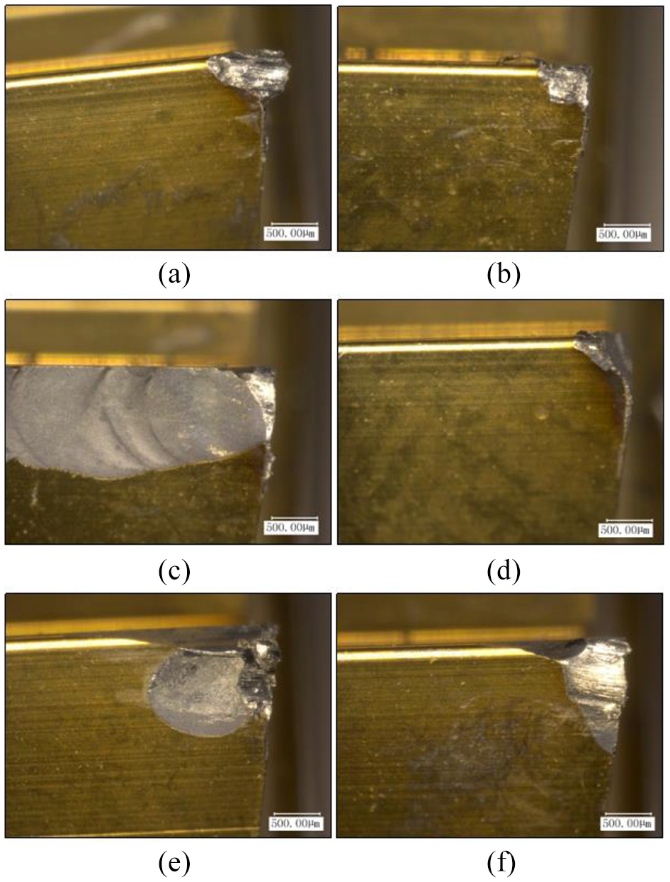
In the process of machining, the wear phenomena on the tool flank surface will also affect machining quality. Figure 15 shows the left flank surface of the tool. It can be seen that in UVAT the degree of wear on the left flank surface is significantly lower than that in the case of CT. When the cutting speed is 12 m/min, the degree of tool wear on the left flank surface is slight in both machining methods, which is similar to wear on the rake face. At the cutting speed of 30 m/min, the left flank surface of the tool has a large wear area. Figure 16 shows the flank surface of the tool on the right side. It can be seen that when the cutting speed is 19 m/min, the flank surface in CT is badly worn. In contrast, the degree of damage of the tool’s flank surface is obviously improved in the case of the UVA machining process even though there is still edge breakage on the tool surface. By comparing the wear patterns in different sections of the tool after UVA machining, it can be found that UVAT effectively reduces tool wear. On the contrary, during the CT process, there is a large area with tool edge breakage, seriously affecting the processing quality. In addition, tool wear becomes considerably more severe when the cutting speed is set to 30 m/min in both machining methods.
Flank wear of the tool on the left side (magnified 100 times): (a) CC: Vc = 12 m/min; (b) UVC: Vc = 12 m/min; (c) CC: Vc = 19 m/min; (d) UVC: Vc = 19 m/min; (e) CC: Vc = 24 m/min; and (f) UVC: Vc = 24 m/min.

Flank wear of the tool on the right side: (a) CC: Vc = 12 m/min; (b) UVC: Vc = 12 m/min; (c) CC: Vc = 19 m/min; (d) UVC: Vc = 19 m/min; (e) CC: Vc = 24 m/min; (f) UVC: Vc = 24 m/min; (g) CC: Vc = 30 m/min; and (h) UVC: Vc = 30 m/min.
Conclusion
This article studies the UVA thread turning technology of Inconel 718 which is difficult to machine using CC methods. The advantages of the UVAT technology in the processing of hard materials are theoretically analyzed. According to the processing characteristics of Inconel 718, UVAT cutting experiments were carried out on this high-temperature alloy material to explore the impacts of this machining technology. The effects of machining parameters on the processing performance were analyzed. Based on the theoretical assessment and experimental results, the technical characteristics of UVAT were highlighted. The main conclusions of this study are as follows:
By analyzing the tool path in UVA machining, it can be seen that, under the premise of keeping the vibration frequency constant, reducing the cutting speed and increasing the ultrasonic amplitude reduce the contact time between the tool and the workpiece surface in each vibration cycle, which leads to improved surface processing quality and reduced tool wear.
The experiments carried out verify the feasibility of the experimental setup. The comparison results show that the UVA thread cutting process can be stably completed. It can also be concluded that UVA thread machining effectively improves surface quality and processing performance by comparing the surface morphologies of the thread teeth machined by the two processing methods.
In the cutting experiments of Inconel 718, it was found that under different parameters the surface roughness obtained by UVA processing is always lower than that obtained by CT. UVAT performance is further improved by appropriately reducing the cutting speed and increasing the ultrasonic amplitude.
More desirable chip shapes are obtained in UVAT as compared to the CT method. Most chips in the UVA case are of a continuous spiral shape with smoother edges. In addition, by comparing the wear patterns in different sections of the tool after UVA machining, it can be found that UVAT effectively reduces tool wear.
Footnotes
Handling Editor: James Baldwin
Declaration of conflicting interests
The author(s) declared no potential conflicts of interest with respect to the research, authorship, and/or publication of this article.
Funding
The author(s) received no financial support for the research, authorship, and/or publication of this article.