
Abstract
This article utilizes the finite volume method to solve the problem incorporating rarefied flow and heat transfer characteristics inside concaved cavities. Cavities are used in many applications, one of which is building insulation to reduce heat loss from walls. In this article, the influence of the aspect ratio (B/H), the tilt angle (θ), Knudsen number (Kn), and Rayleigh number (Ra) on these characteristics were studied. Parameters ranges were
Introduction
Natural convection mode of heat transfer found in enclosures of different geometries is of importance to many engineering researchers due to its broad applications, such as those found in nuclear reactors and solar energy collectors. For example, Terekhov et al. 1 numerically studied using Navier–Stokes and energy equations and Boussinesq approximation of laminar free convection flow and heat transfer inside a cavity that consists of two vertical parallel isothermal walls; the studied channel was equipped with two thin adiabatic fins on its walls. Using finite volume method (FVM), Sahi et al. 2 conducted a numerical investigation using FVM and Boussinesq approximation of the magnetic field effect on free convection heat transfer induced by two-dimensional buoyancy effect between two different top and bottom walls’ temperatures inside a rectangular grooved cavity subjected to isothermal walls.
Many scholars have investigated natural convection in rarefied and microflows. Referring to Karniadakis et al., 3 the rarefied and microflows can be classified based on Kn as continuum flow when Kn = 0, slip flow if 0 < Kn < 0.1, transitional flow if 0.1 < Kn < 1, and free molecular flow when Kn > 1. For instance, Yang et al. 4 investigated the natural convection with combustion as a heat source in microcavities. They numerically investigated the cavity depth impact on lean hydrogen/air flames combustion efficiency inside a dual-cavity micro-combustor. Their results revealed that with increasing cavity depth, the combustion efficiency varies oppositely, and such trends were observed for lower and higher combustor inlet velocities. Ning et al. 5 experimentally investigated non-pre-mixed methane-air combustion inside meso-scale Y-shaped combustors including both with fibrous porous structure and without.
Al-Kouz et al. 6 investigated numerically rarefied flows in cavities in which the hot wall is attached to solid or porous fins; their investigation revealed the influence of Kn, Ra, the fins tilt angle, and porosity on the flow and heat transfer characteristics inside the studied cavity. In addition, a correlation of Nu among the examined parameters is proposed. In another research conducted by Al-Kouz et al., 7 they studied the thermal behavior of rarefied air flow in two concentric cylinders in which the inner cylinder is attached to a solid fin. They come up with a correlation for Nu as a function of Kn, Ra, and the fin tilt angle. Moreover, Al-Kouz et al. 8 investigated the heat transfer enhancement of rarefied flows employing Al2O3 nanosolid particles. They found that Nusselt number increases as the volume fraction of the nanosolid particles increases. Moreover, they proposed a correlation of Nusselt number as a function of all the investigated parameters in the study. In addition, the entropy generation optimization for rarefied nanofluid flows inside a square cavity that is equipped with two solid fins at the hot wall is studied by Al-Kouz et al. 9 In their study, they defined the conditions in terms of Ra, Kn, and the nanosolid particles volume fraction at which the minimum entropy generation is obtained.
In their work, Eskandari and Nourazar 10 employed the first, second, and third orders of the time relaxed Monte Carlo (TRMC) scheme (TRMC1, TRMC2, and TRMC3 schemes) to numerically investigate the lid-driven microcavity flow with various lid velocities and Kn, (0.005 ≤ Kn ≤ 0.1). They concluded that a third-order approximation of the truncation TRMC3 method used in their study as an alternative to the standard direct simulation Monte Carlo (DSMC) method in simulating the lid-driven microcavity flow may provide reasonably accurate results for the Kn (0.005 ≤ Kn ≤ 0.1).
Taheri et al. 11 numerically investigated one-dimensional Fourier heat conduction of argon gas at the early slip regime problem. They reported in their comprehensive study the convergence behavior of the simplified Bernoulli trial (SBT) collision scheme used in the DSMC. In their problem, they considered rarefied gas confined between two infinite parallel plates with various wall temperatures. They concluded that the SBT algorithm accurately predicts the wall heat flux by decreasing the average number of particles per cell to one particle or even less. This is valid for a given constant Δx/Δt.
Rana et al. 12 numerically investigated the steady flow and heat transfer characteristics of a two-dimensional square cavity that contains rarefied argon gas with the heated bottom wall using Navier–Stokes–Fourier equations and the regularized 13 moments (R13) equations. Results demonstrated that the R13 equations provide satisfying results in the transition regime including flow patterns and showed acceptable agreement with DSMC, whereas conventional Navier–Stokes–Fourier equations could not cope with this regime. In addition, Dadzie and Christou 13 investigated the rarefied gas heat transfer inside a lid-driven cavity flow induced by promptly heating and cooling opposite walls for various flow regimes. They simulated the flows using a volume diffusion model as standard Navier–Stokes–Fourier extension. They presented obtained numerical simulations and compared them with standard Navier–Stokes–Fourier equations. For higher Kn, the volume diffusion model was able to simulate non-local equilibrium effects in the corners of the cavity, which could not be captured by standard Navier–Stokes–Fourier model. Furthermore, additional studies on natural convection flow and heat transfer characteristics inside rectangular cavities were conducted.14–16
In the past decades, wavy and concaved enclosures attracted many researchers as a way to enhance the heat transfer characteristics inside cavities. These wavy enclosures serve in many applications, for instance, cooling of electronic devices, thermal insulation, and underground cable systems.
In the literature, many numerical and experimental researches conducted are related to cavities with square or rectangular geometries. Meanwhile, few researchers investigated the flow inside wavy and concaved cavity configurations due to the problem complexity. For instance, Mahmud and Fraser 17 investigated the thermal behavior of cavities that have two walls and are wavy, while the other two are straight. The results showed flow inside the cavity using streamlines, isothermal lines, and thermal field. For the above configuration, they presented local and overall Nusselt number distributions.
Furthermore, Mahmud and Islam 18 numerically studied the entropy generation in wavy cavities. Results showed the heat transfer rate by plotting the local and overall Nusselt number distributions in the cavity. They presented contour plot and volume-averaged entropy generation rate of Bejan number. Where, Bejan number is defined as the ratio of heat transfer irreversibility to the total irreversibility due to heat transfer and fluid friction.
Varol and Oztop 19 examined the natural convection without heat generation in a cavity where the bottom wall is shallow and wavy with constant hot temperature. Their results indicated that heat transfer increases by the increase in Ra and aspect ratio, which is the average channel height to amplitude height of the wavy wall of the channel, and the decrease in non-dimensional wavelength. Surface radiation affects the natural convection, and this effect on cavities with wavy wall was investigated by Sheremet and Miroshnichenko. Authors formulated the governing equations in non-dimensional form, and those equations had been solved numerically. Authors presented their results in the form of streamlines and isotherm lines, and Nusselt number was calculated. 20
Jayhooni and Jafarpur investigated the heat transfer, free convection, from isothermal concaved and convex body shapes numerically. Several body shapes were investigated; one of which is the height over width(H/D = 2) under laminar condition. The Nusselt number was found for those cases under various Ra numbers. 21 Concaved and convex collectors are very common in solar collector systems. Singh and Singh investigated natural convection in flat plate solar air heater using numerical methods validated experimentally. Results showed that the unit pressure drop causes a significant increase in Nusselt number. 22
Cavity utilization in thermal insulation was investigated heavily in the literature; for example, Byrne at al. 23 investigated cavity as insulation in Irish homes, and the results were compared with external wall insulation. They concluded that small concaved cavities could be utilized in layers inside walls to improve thermal insulation.
Few studies were conducted to investigate the effect of curved walls on rarefied flow and heat transfer characteristics inside wavy and concaved geometries. Up to the authors’ knowledge, there is no previous study that has tackled the rarefied flow and heat transfer characteristics in concaved cavities. The current investigation aims to study the natural convection heat transfer of rarefied flows in concaved cavities and documents the effect of different flow and geometric parameters on the heat transfer characteristics.
Problem statement and solution methodology
Figure 1 shows a schematic diagram of the cavity geometry considered in the current investigation. The cavity includes top cold isothermal wall, bottom hot isothermal wall, and insulated sidewalls.
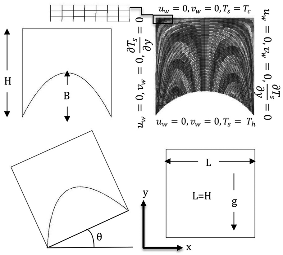
Schematic diagram of the geometry under consideration.
The buoyancy-driven rarefied flow is considered laminar, steady, and two-dimensional. The gas density is modeled by Boussinesq approximation, and the rest of the thermos physical properties are assumed constant. Furthermore, the continuum governing equations utilized in conjunction with the slip velocity and temperature jump boundary conditions used to solve for the fluid motion and heat transfer parameters.
The continuity, momentum, and energy-governing equations for gas flow and heat transfer characteristics in the studied cavity in Cartesian coordinates are as follows. 24
Continuity

x-momentum

y-momentum

Energy

The boundary conditions considered for the studied problem are the finite temperature at the surfaces of the bottom and top walls. At the bottom wall,
The velocity slip at all walls is defined as follows

Since the walls are stationary

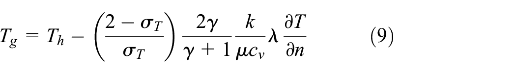
The temperature jump condition applied to all walls is defined as follows

In previous equations,
For the top wall, T = Tc, thus equation (7) becomes

Similarly, the temperature of the gas at the bottom wall is given by
The mean-free-path length is defined as

where

The spacing between the hot and cold walls shown in Figure 1 is denoted by L. B in Figure 1 shows the boundary conditions.
Fourier’s law of conduction used to calculate the local heat flux at the bottom wall is given as follows

Since the problem is steady, the rate of heat transfer at the curved surface obtained by integrating the local heat flux along the surface is given as

The average heat transfer coefficient of cavity bottom wall is obtained from the following

The Nusselt number is calculated from

Introducing the following non-dimensional parameters to the above equations to obtain the non-dimensional form of the governing equations is


The non-dimensional governing equations are as follows.
The non-dimensional x-momentum equation is

The non-dimensional y-momentum equation is

where
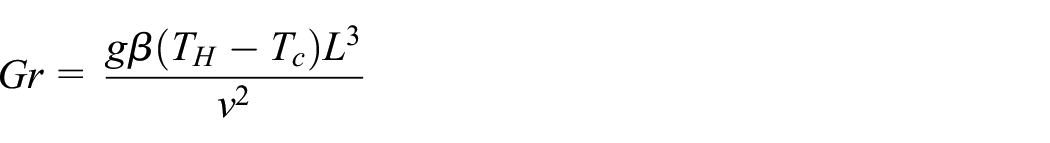
and

The non-dimensional energy equation is

Based on the dimensionless proposed parameters, the thermal boundary conditions are as follows:
At the bottom wall:
At the top wall:
Solution method
The governing equations along with the specified boundary conditions are solved numerically by the FVM using FLUENT 18. A computer-aided design (CAD) modeler and a meshing tool are used to create the computational domain, as shown in Figure 1. For H/L = 1, the mesh was increased in sizes, such as
The spatial discretization of the steady governing equations is carried out by using the second-order upwind scheme. The SIMPLE algorithm was used to tackle pressure–velocity decoupling, and the pressure discretization was performed via the PRESTOalgorithm.
27
Simulations assumed totally diffusive walls, so the momentum and thermal accommodation coefficients,
The convergence was monitored by residuals for the solution, and it is considered converged for the mass and velocity when they are less than 10−3, and the residual for energy equation is less than 10−6.
Model validation
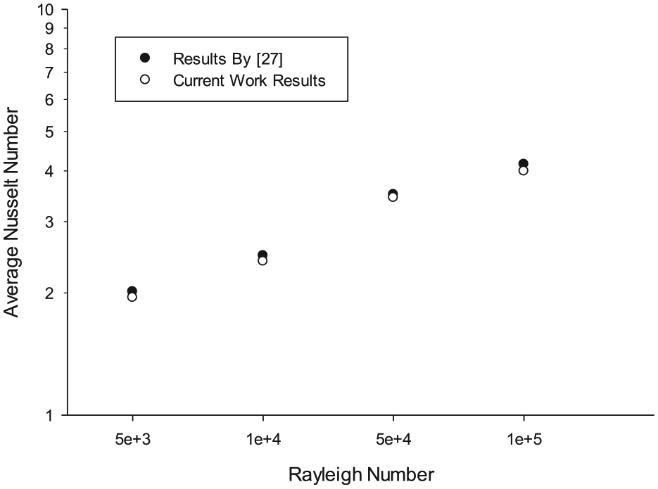
Model validation was performed by reproducing the experimental results found by Globe and Dropkin. 26 The current software code was able to predict Nu given by the following equation
This equation is valid for
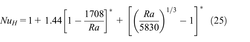
Note that at Kn = 0, the no-slip condition holds true, and this corresponds to the case of the macro cavity. Model validations for slip and jump boundary conditions in rectangular cavities conducted by the Alkhalidi et al. 24 are presented in Figure 3 and compared with other published papers in the literature.
Normal heat flux comparison between current study and Rana et al. 12
Note that the normal heat flux from the hot surface to the cold surface of the cavity is presented in Figure 3. Current work results lay between DSMC and R13 models. Thus, one can conclude that this study simulation technique is capable of predicting the thermal performance within an acceptable accuracy.
Discussion of results
Figure 4 shows the velocity streamlines on the left-hand side and the temperature contours on the right for cases where B/H = 0.25, Kn = 0, and different Ra. Temperature, presented in Figure 4, is normalized and varies between 0 and 1, and the presented scale is the non-dimensional temperate T* plus 300. This was done to guarantee the correct material properties’ calculation by Fluent software.

Velocity streamlines and temperature contours inside the cavity for different Ra (B/H = 0.25 and Kn = 0).
The graph shows that when Ra is below 3 × 10⁶, the streamline contours form two separate identical regions inside the cavity. Moreover, the flow strength increases as Ra increases. For the case where Ra = 3 × 10⁶, one large circulating flow region is formed in the cavity.
For Ra = 3 × 10³ case (not shown), near the cavity bottom wall, parallel temperature contours that fit the modeled geometry are observed. In the rest of the geometry, nearly straight temperature contours are formed, and this indicates that conduction is the dominant heat transfer mode inside the cavity. For Ra = 3 × 10⁴ case, these parallel temperature contours lines cover most of the cavity region, and this demonstrates the presence of the convection mode of heat transfer inside the cavity. For the case of Ra = 3 × 10⁵, more distortion happens to the contours, and as Ra increases, extra circulations and distortion of these contours occur as the convection heat transfer becomes the dominant mode inside the cavity, and therefore, better heat transfer is achieved.
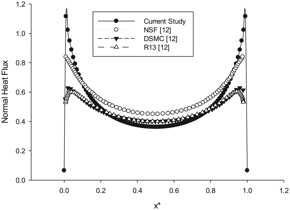
Figure 5 illustrates the velocity streamlines on the left and the temperature contours on the right for the case when Ra = 105, Kn = 0, and B/H = 0.25. The graph for the streamlines shows that an ellipsoidal-shape contour is formed practically in the middle of the cavity. As the angle increases, the size of the ellipsoidal-shape increases. For the temperature contours, it is noticed that more circulation and distortion is happening in the case when the tilt angle (θ) is 60o.
Velocity streamlines and temperature contours inside the cavity, Ra = 105, B/H = 0.25, Kn = 0, and different tilt angles.
In Figure 6, the velocity streamlines are plotted on the left, while the temperature contours are plotted on the right for the case where B/H = 0.25, Ra = 105, and an angle 0o. The graph shows that as Kn increases, no significant influence observed in both the velocity streamlines and temperature contours. In addition, the trend of velocity streamlines and temperature contours are examined for the case of B/H = 0.5, and the same trends are noticed compared to the case of B/H = 0.25.
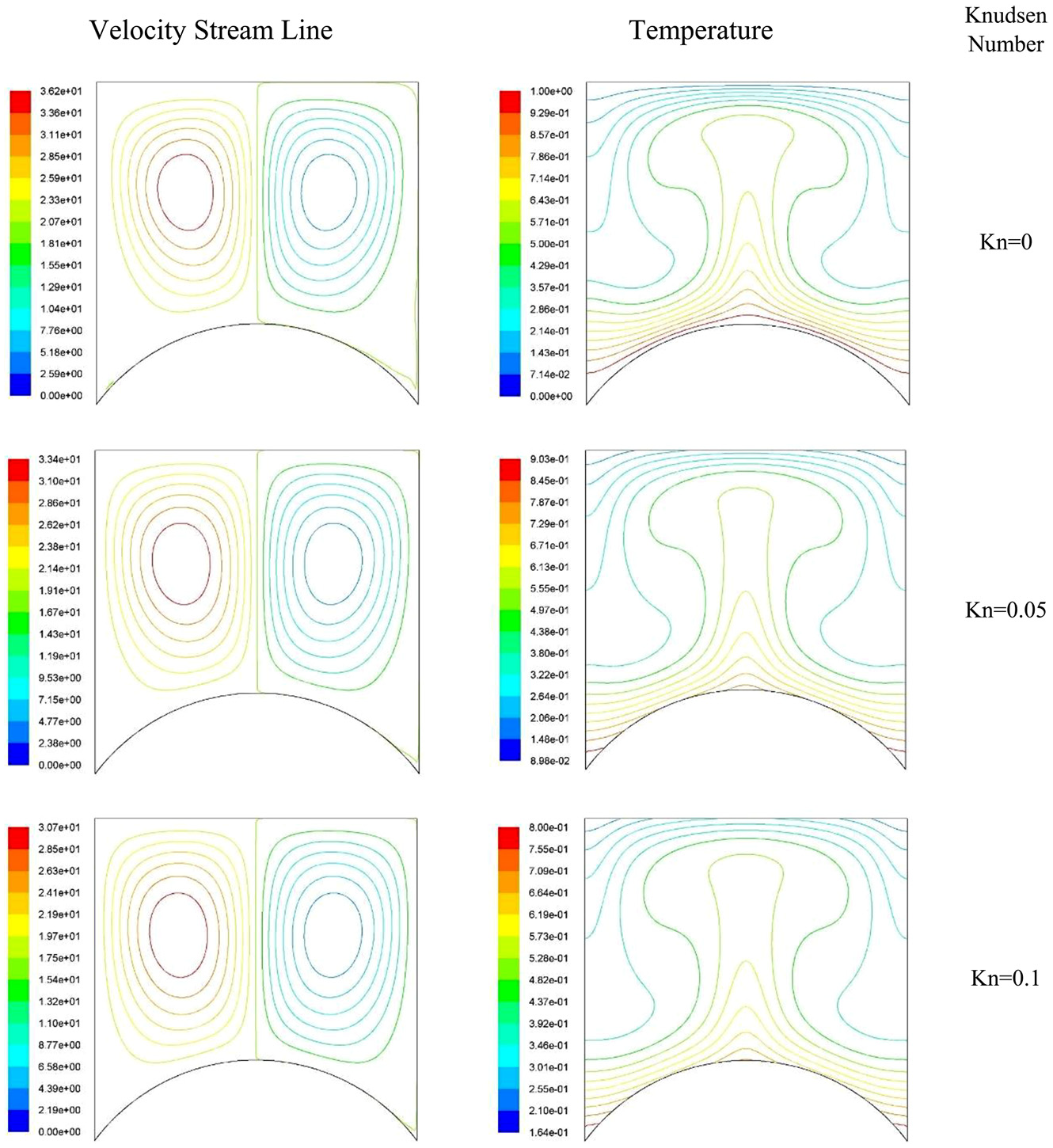
Velocity streamlines and temperature contours inside the cavity (Ra = 105, B/H = 0.25, and different Kn).
Figure 7 demonstrates that B/H and Kn influences the velocity magnitude along with the axial position at the middle of the cavity height. Kn number was calculated from the mean-free-path length (equation (10)). The Kn number was varied by changing the L-J values in Fluent software. The graph reveals that the velocity slip at the boundaries increases as Kn increases due to the slip boundary condition, which reduces the velocity of the flow inside the cavity. Moreover, as B/H increases, the velocity magnitude decreases for the same Kn. It is clear from the graph that as B/H increases, the location of the maximum velocity moves toward the center of the cavity. It is near the cavity boundaries for the case of B/H = 0.
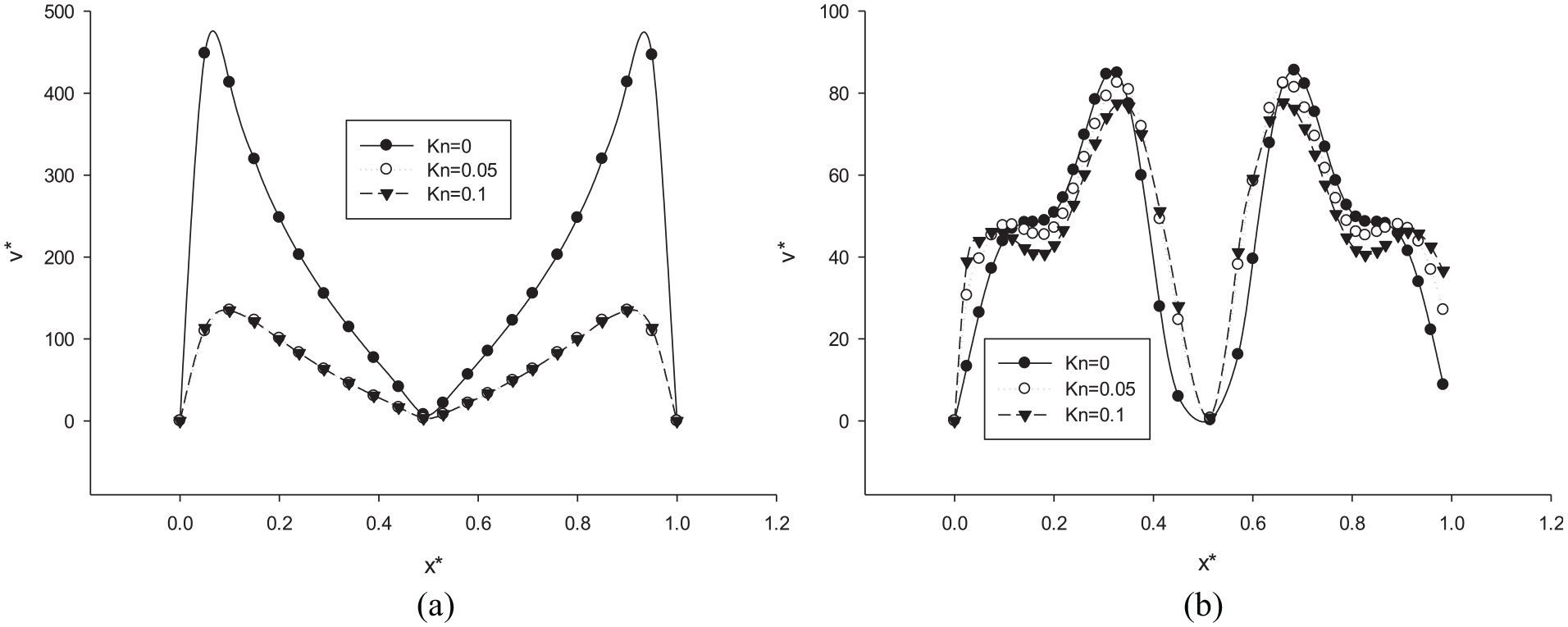
The variation in the velocity magnitude with the axial position at various Kn and B/H: (a) B/H = 0 and (b) B/H = 0.5.
The effect of B/H on the velocity magnitude is demonstrated in Figure 8 for the case where Kn = 0. It is observed from Figure 8 that as B/H increases (i.e. the flow region is more confined), the magnitude of the velocity near the walls decreases. Since less circulation and distortion occurs near that region, the amount of heat transfer is reduced and, therefore, a low value of Nu is attained.

The variation in the velocity magnitude with the position along the cavity at mid-plane for Kn = 0 and various B/H.
Figure 9 depicts the variation in the velocity magnitude along with the axial position of the cavity for the cases where Kn = 0 and different B/H and θ. The graph indicates that as the value of θ increases, the velocity magnitude decreases near the walls for all cases. This is attributed to the decomposition of the gravitational force in the x and y directions. Moreover, the graph demonstrates that as the θ increases, the velocity magnitude decreases for the same B/H.
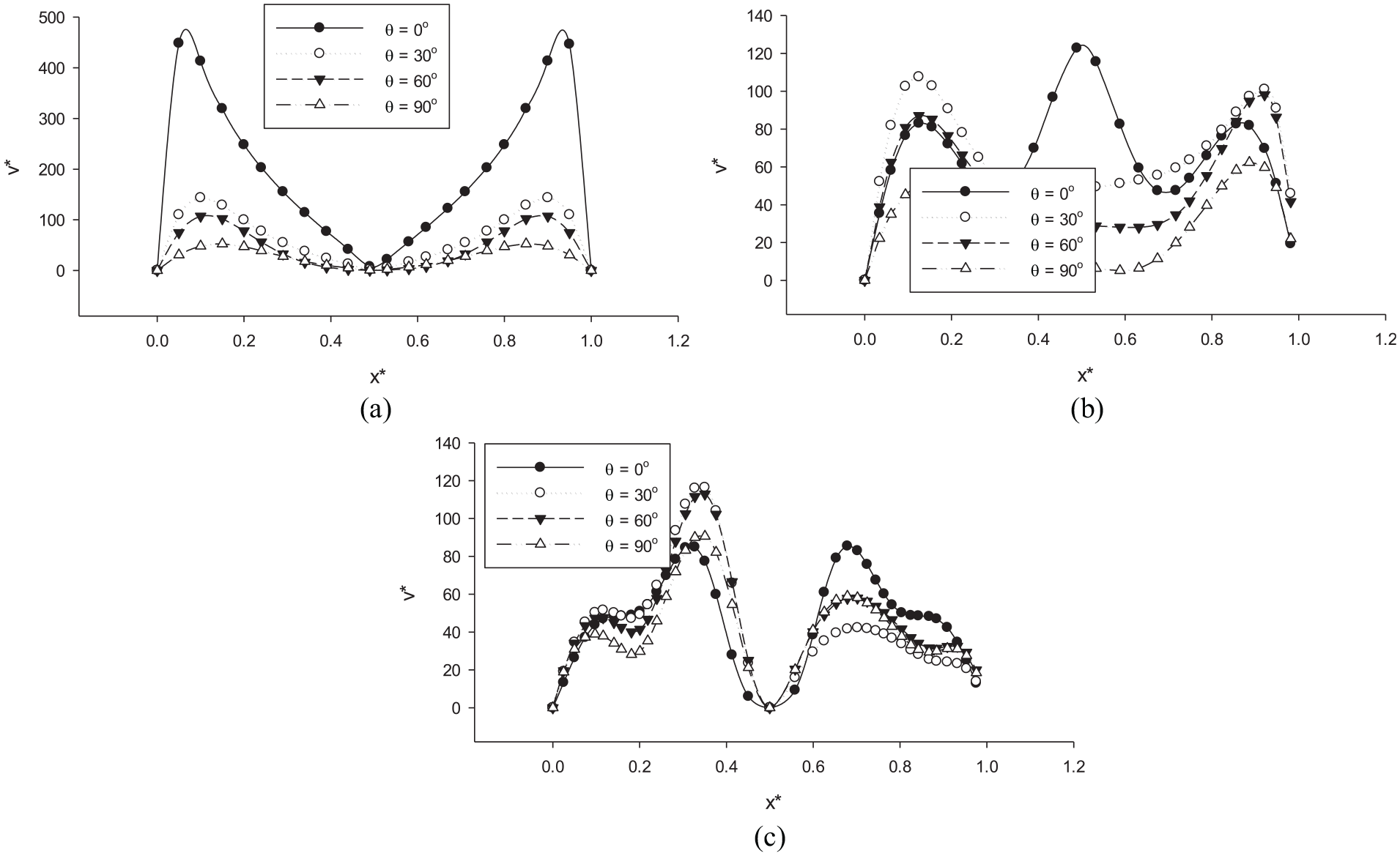
Variation in the velocity magnitude with the axial position at Kn = 0, various tilt angles, and B/H: (a) B/H = 0, (b) B/H = 0.25, and (c) B/H = 0.5.
In Figure 10, the temperature is plotted against the axial position of the cavity for the cases where Ra = 105, and different Kn covers the continuum and slip flow regimens and two different values of B/H of 0.25 and 0.5. The graph indicates that the temperature jump increases near the boundaries as Kn increases for the two cases of B/H = 0 and 0.5 due to the temperature jump boundary condition. In addition, the graph shows a constant temperature in the middle of the cavity for B/H = 0, while for B/H = 0.5, a minimum temperature occurs near the boundaries, while the maximum temperature is observed at the middle of the cavity. Increasing the aspect ratio will reduce the flow region, and the temperature near the hot wall will directly affect the flow in the middle of the cavity.

The variation in the temperature with the axial position at various Kn and different B/H: (a) B/H = 0 and (b) B/H = 0.25.
Figure 11 demonstrates the variation in the temperature along with the cavity axial position for different B/H, Kn = 0, and Ra = 105. The graph shows that for the case where B/H = 0, a flat temperature is observed in most of the regions inside the cavity, and difference in the temperature is noticed near the boundaries of the cavity. For the case of B/H = 0.25, temperature decreases for x* greater than 0.6. For B/H = 0.5, the temperature increases as the axial position increases.

Variation in the temperature with the axial position Kn = 0 and various B/H.
Figure 12 demonstrates temperature variation along with the cavity axial position for various tilt angles θ and different B/H. The graph shows that as the angle increases, the temperature decreases near the cold wall and increases near the cavity hot wall for all given values of B/H.

The variation in the temperature with the axial position at Kn = 0, various tilt angles, and B/H: (a) B/H = 0, (b) B/H = 0.25, and (c) B/H = 0.5.
Figure 13 illustrates variations in the average Nu with Kn for different B/H at Ra = 1 × 10⁵ and zero tilt angle. The graph indicates that as B/H increases, the average Nu decreases. Furthermore, as Kn increases, the average Nu decreases due to the velocity slip and temperature jump boundary conditions. For example, if we take the case where B/H = 0 and Kn = 0 to be the reference case for comparison purposes, varying B/H to be 0.25 and 0.5 will yield Nu of 3.69 and 3.35 with a decrease of 6.34% and 15% compared to the reference case. In addition, the case of Kn of 0.1 and B/H = 0 yields a Nu of 3.71 with a decrease of 5.81% compared to the reference case.

Variation of Nu with Kn at various B/H for Ra = 105 and θ = 0o.
Results found in Figure 13 agrees with Alkhalidi et al.’s 24 finding for H/L investigation. Reducing the space in the cavity limits the strength of fluid circulation within the cavity, which reduces the convection heat transfer between the hot and cold walls of the cavity. Thus, this finding supports the idea of using a concaved cavity for insulation purposes.
Figure 14 shows the variation of Nu with the tilt angle, θ, for various B/H, and Ra = 1 × 10⁵ at Kn = 0. The graph revealed that as B/H increases, the average Nu decreases. Moreover, as the tilt angle increases up to a critical value that was found to be 60°, the average Nu increases. Beyond this critical angle, the average Nu decreases. The graph shows an increase of 18.3% in Nu at the critical angle of 60° compared to 0° at B/H = 0. Also, the graph shows an increase of 11.1% at this critical angle and 0o for B/H = 0.25 case. Moreover, the graph shows an increase of 0.3% at the same critical angle compared to 0° and B/H = 0.5 case.

Variation of Nu with the tilt angle at various B/H (Ra = 105 and Kn = 0).
Figure 15 depicts the variation of Nu with Ra for different B/H. The graph illustrates that as Ra increases, the average Nu increases because the convection heat transfer becomes dominant inside the cavity. Moreover, as B/H increases, the average Nu decreases. For instance, at B/H = 0 and Ra = 1 × 10⁵, the Nu is 3.94 for the same case, but Ra = 1 × 10⁶, and the Nu is 6.84 with an increase of 73.6%.
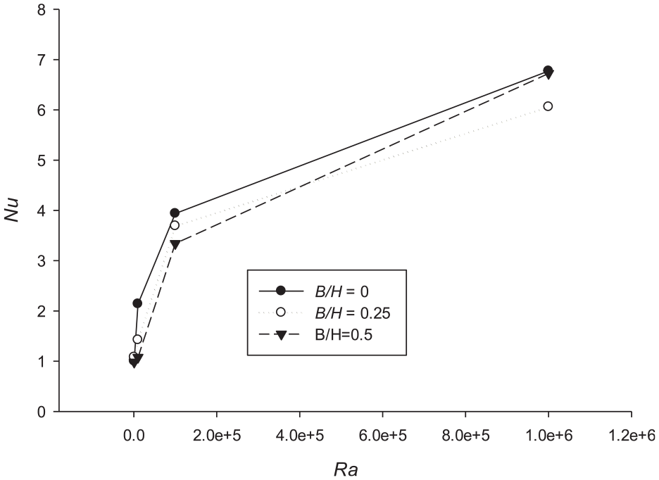
Variation of Nu with Ra at various B/H and θ = 0° and Kn = 0.
Finally, a correlation of Nu including all the investigated parameters in this study is proposed in equation (26). The correlation yields R2 = 0.965, and the number of data points used to achieve this correlation is 300

the angle (360 – θ) has to be converted from degrees to radian.
Conclusion
In this article, the computational fluid dynamics model and finite volume technique are used to study rarefied flow and heat transfer characteristics inside a concaved cavity. The effects of Knudsen number (Kn), Rayleigh number (Ra), the tilt angle (θ), and aspect ratio (B/H) on these characteristics are investigated. Ranges of these parameters are as follows:
Results illustrate a declining effect of Kn and aspect ratio on the average Nu. Moreover, the maximum average Nu is observed at a given critical tilt angle
Footnotes
Appendix 1
Handling Editor: Jose Ramon Serrano
Declaration of conflicting interests
The author(s) declared no potential conflicts of interest with respect to the research, authorship, and/or publication of this article.
Funding
The author(s) received no financial support for the research, authorship, and/or publication of this article.