
Abstract
This article describes a novel multi-robot formation control based on a switching technique that allows follower robots to maintain formation when the leader robot’s direction changes rapidly or unexpectedly. The formation pattern is determined using Virtual Robot’s Center of the multi-robot formation. To avoid collision, the formation of robots reformed in optimal size by estimating the distance between the robot and an obstacle in real time. When the leader robot suddenly changes its direction, waypoints of follower robots are switched and the formation is quickly reconstructed. This prevents follower robots from colliding with each other and reduces their radius of movement and allows them to follow the leader robot at higher speed. The proposed method which is inherently a flexible control of multi-robot formation guarantees collision avoidance and prevents sudden changes in waypoints of the system by gradually changing its size. The validity of the proposed method is demonstrated via simulation and experimental results.
Introduction
Multi-robot navigation in formation has received extensive attention in the past and been employed for various tasks, such as surveillance, inspection, factory automation, and logistics. Robots may be required to navigate in formation, for example, to maintain a communication network, to collaboratively manipulate deformable objects, or transportation of cable-suspended loads.1–3 Flexible multi-robot formation control approaches can be classified depending on the knowledge of the initial positions of the robots. If the positions of robots are known, the positions and heading angles of the follower robots are estimated from the leader robot. In this case, the follower robots are controlled to maintain a constant distance from the leader robot and moves to the next position determined by the leader robot. In case that the initial positions of the robots are unknown, the robots move to form a targeted formation using fixed distances from arbitrary points, by sharing coordinating information on relative position and heading angles. 4
Robots’ obstacle avoidance which is a fundamental requirement for multi-robot formation has different approaches according to detection methods.5–8 Jin et al.9,10 proposed a new algorithm where robots navigate through surroundings of obstacle by recognizing detected obstacles as circles. Over the past decades, the control problems for mobile robots have been extensively studied. When designing controllers, depending on whether the non-linear dynamics are approximated/linearized, the control methods are classified into linear control and non-linear control. In Dai et al.,11,12 robots avoid collision with obstacles as well as other robots based on predicted topography according to detected distances. In general multi-robot formations, robots share information on the positions of other robots for navigation. The robots use potential field method to avoid collision with other robots on overlapping paths or avoid path conflict by priority within detection range. In Dai et al., 11 since non-linear control methods are developed on the basis of the original non-linear dynamical equations, they can maintain satisfactory control performance even when the state variables are far from the equilibrium point. According to Dai et al., 12 because it is difficult for the dynamics of the robot to produce the perfect velocity as the kinematic controller, the dynamic controller is also used in this article. In Das and Kar, 13 a control structure that makes possible the integration of a kinematic controller and an adaptive fuzzy controller for trajectory tracking is developed for non-holonomic mobile robots. The system uncertainty, which includes mobile robot parameter variation and unknown non-linearities, is estimated by a fuzzy logic system. In practical point of view, this approach can be used for multi-robot formation effectively.
In this article, we propose a new formation maintenance method of mobile robots and the movement method for detection and avoidance of fixed obstacles. Under the proposed method where Virtual Robot’s Center (VRc) determines the size of the formation of robots, robots can effectively change and restore the formation according to the geometry of the obstacle. The proposed formation is mainly determined by using the VRc of the multi-robot formation. Based on the position of the leader robot, follower robots form the equilateral triangle formation centered on the VRc. This makes it possible to change the formation of robots adaptively depending on the situation. In addition, when the leader robot suddenly changes its direction, follower robots switch their positions and effectively rapidly form a multi-robot formation in real time. As a result, since the moving radius of the follower robots is reduced drastically, follower robots maintaining a regular triangular pattern track leader robot fast.
Robot model
As in a mobile robot kinematics model,
14
the velocity and angular velocity of robot i,


Coordinate system for a mobile robot in reference coordinate system.
Localization of a differential mobile robot is achieved via dead reckoning based on an odometer. Thus, it can be expressed by equations (2) and (3) according to the real robot’s state and the predicted robot’s state, respectively

In equation (2), R is the position and direction of the ith real robot and ui − 1 is the linear velocity of each wheel of the i − 1th robot; it is also the odometry value. δui − 1 represents the linear velocity disturbance value of each wheel at the i − 1th robot

Equation (3) employs dead reckoning to estimate the state of the robot;
Using equation (2), the state of the next robot can be expressed as equation (4), according to the current state, linear velocity, rotational speed, and sampling time

Utilizing equations (1) and (4), the dead reckoning navigation for predicting the state of the robot in the next step has the form of equation (5)

It is assumed without loss of generality that the rotational speed in the above equation is not affected by disturbance.
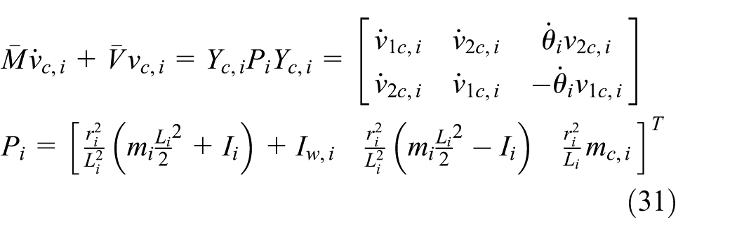
The motion of the mobile robot with torque is as follows

where

where mass regarding to robot body and wheel is
VRc and obstacle avoidance
VRc
Multi-robot navigation in formation has received extensive attention, with many works considering collision-free scenarios because multi-robot system shows obvious advantages over single robot, including greater flexibility, adaptability and robustness. Robots maintain specific formation while moving along path.
In the proposed method, the center point VRc of a multi-robot formation is set using a constant distance “a” with reference to the leader robot; distances “b” and “c,” which are the same distance as “a,” are divided at the same angle around this point and are calculated according to the positions of follower robots 1 and 2. In this study, the distance “a” between VRc and the leader robot Li is the reference set distance, and “a” can be changed from its initial setting to accommodate the environment.
Figure 2 has a VRc resulting from the initial value “a” of the multi-robot formation. Here, “a = b = c,”“a” is changed to “a′” if the size of the original formation is changed to accommodate the surrounding environment. As VRc is moved to the coordinates of VRc′, a change of formation is stably performed.

VRc of multi-robots.
For flexible control of the multi-robot formation, the basic shape is formed by setting the initial value “a.” For this purpose, a process is applied to the other scattered robots to be involved in the formation. After execution of decentralized control, the robots individually request information on other’s states and then begin to move after deployment via centralized control. The conventional robot formation is formed at a predetermined position. 4 In this study, a formation is formed at not only a predetermined position but also during the robots’ movement toward their targets. However, in this article, the formation is formed and maintained during the robots’ movement as shown in Figure 3.

VRc formation control.
As shown in Figure 3, the motion of follower robots 1 and 2 is expressed by equations (7) and (8), respectively. The formation coordinates of the follower robots, calculated according to the initial value at any position, are set as the target states in the next step


When the robots set a formation, the position of a follower robot can be expressed by the coordinates of VRc and the distances b and c from the coordinates. The coordinates of the VRc can be represented by the current coordinates of the leader robot and the distance “a”. The coordinates of the center point VRc are expressed as in equation (9) and the coordinates of follower robot 1 has the form of equation (10)


In equation (10),

Obstacle and collision avoidance
Obstacle avoidance
Robots in a formation must perform complex maneuvers to avoid or pass obstacles while maintaining the formation. When the robots in formation move, the leader robot leads the follower robots, detects and judges obstacles, and avoids and passes through obstacles while deforming the formation fluidly.
As shown in Figure 4, in order to pass through the space between two obstacles, the robot group formed should consider the following parameters: distance
Condition of minimum formation:
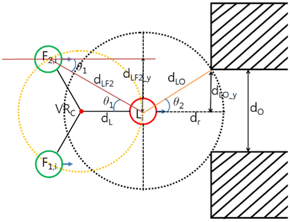
Obstacle avoidance of multi-robot formation.
The position and angle of each robot and obstacle are calculated using equations (12) and (13), which respectively, take the form of the Pythagorean Theorem and the cosine second law


Collision avoidance
When robots in formation change their directions to reform the formation, if the trajectories of two follower robots overlap, there is a risk of collision. In this case, we use the repulsive force of a potential field15,16 to set a new waypoint for avoiding collisions and then use an attractive force to retrieve the path.
The attractive potential energy
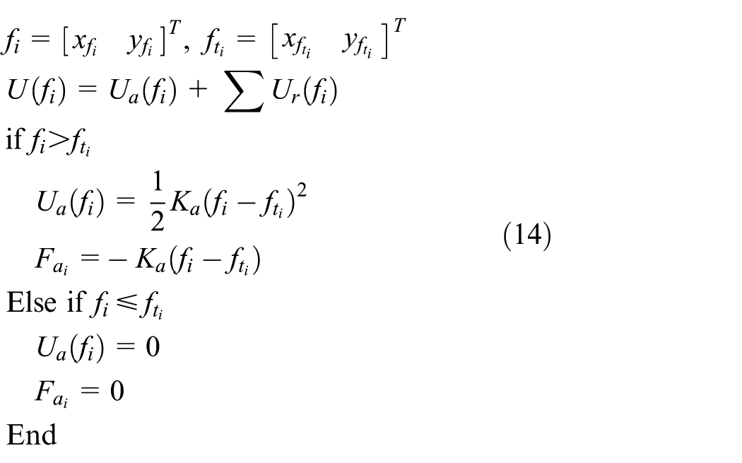
Equation (15) represents the repulsive potential energy

Equations (14) and (15) are applied not only for collision avoidance between robots but also for obstacle avoidance. Using these equations, a new safe waypoint can be calculated.
Movement technique
Adaptive controllers
Define the waypoint model of the robot as


where

As shown in Kanayama et al., 17 the linear and angular velocities are transferred as the following equation
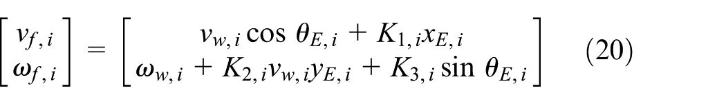
where

To obtain the angular velocities of each wheels, parameters

where

To design

For Lyapunov stability of the system, the parameters are designed as

The differentiation of
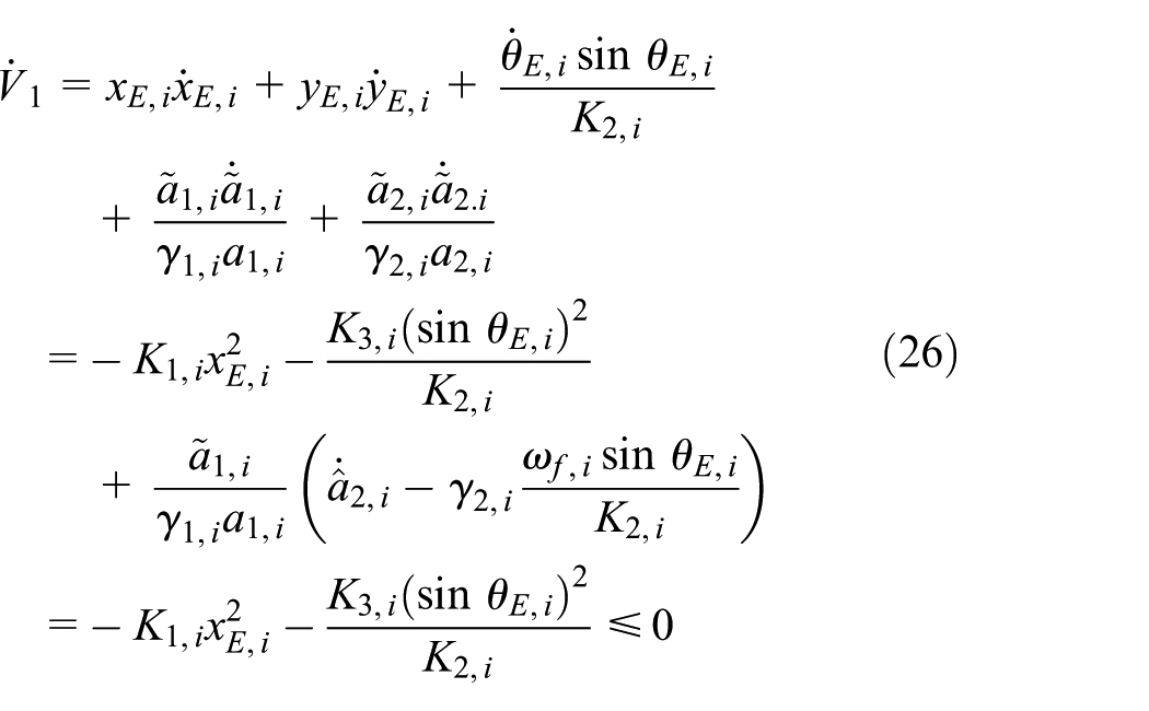
As t→∞,
The velocity tracking errors

Equation (6) is rewritten as

Then

The torque controller is defined as

where
To obtain the torque controller, the Lyapunov function is defined as

The parameters are selected as

The differential of

Formation switching method
The formation switching method is determined by heading change of the leader robot. In Figure 5(a), if the leader robot rapidly changes its heading to follow the path, the i + nth waypoint of the follower robot suddenly changes. As a result, follower robots will excessively move to track their waypoints, but they may fail to follow their paths, depending on the robot’s platform. In this case, the robots should use the proposed formation switching method to track their trajectories, as shown in Figure 5(b). Conclusively, if the heading angle of the leader robot is

(a) Basic formation and (b) formation switching movement.
System block diagram
System block diagram of the entire multi-robot system proposed in this article is shown in Figure 6.

System block diagram.
Simulation
In this simulation, robots use the proposed VRc method to form and maintain a formation. For this purpose, follower robots switch their tracking paths according to the heading angle of the leader robot. When an obstacle is detected, the formation size is reduced step-by-step in order to pass through the obstacle area. After passing through the obstacles, the robots reform their original formation and continue their mission.
Figure 7 shows the process of multi-robot formation while moving. First, the starting points of the leader robot and follower robots 1 and 2 are, respectively, defined as
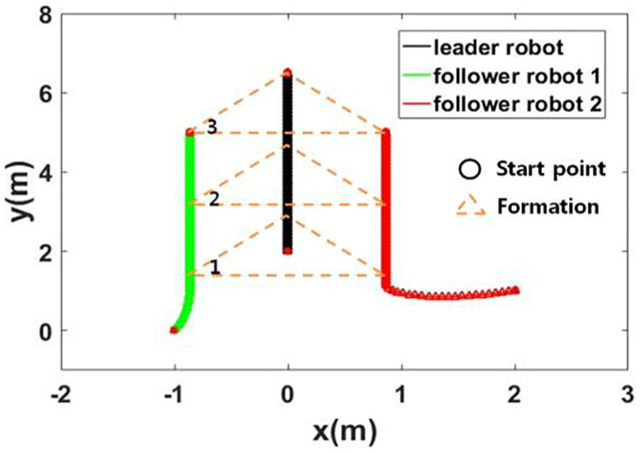
Formation configuration while moving.
Second, when the leader suddenly changes its angle from

Formation switching and VRc of multi-robot formation.
As shown in Figure 9 where the switching method is not applied, the follower robots cannot follow the leader robot properly due to excessive postural changes. Moreover, it is difficult to maintain the formation size.

Excessive movement of follower robots in case of sudden posture change of leader robot.
Third, the formation size can be adjusted by moving the VRc of the robots. As shown in Figure 8, when the leader robot detects the obstacle, it judges whether it can pass through the obstacle by using the proposed method. By determining the distance between two obstacles, the robots can shrink the formation to pass through the obstacles. It can be confirmed that the deformation starts at the 0 point on the x-axis, and the formation scale is reduced at the 2–4 points. After passing through the obstacles, the formation restoration is performed. If the formation size is enlarged suddenly, ineffective movements of follower robots may occur as shown in Figure 10. To prevent this problem, as shown in Figure 8, the size of the formation is gradually increased with consideration of the formation size and the robots’ speeds.

Collision errors occurred when restoring a multi-robot formation.
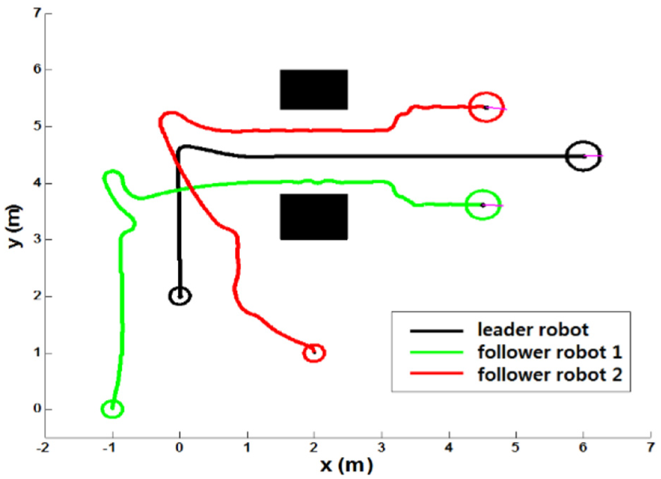
Finally, as shown in Figure 11, if the robot confronts another obstacle after passing through the obstacles, the robots avoid collision with the obstacle and continue generating their paths. The starting points of each robot are

Avoidance path for robots when obstacles are detected.
Figure 12 shows the tracking error of each robot when it follows the path. Figure 12(a) depicts the state error of the leader robot after 0.5 m was added to the x value of the current leader robot coordinates. As shown in the result, when the third obstacle is avoided, the leader robot is maintaining a distance of about 0.5 m, except for the new created path. The y value and the heading angle are finally maintained at 0, and it is clear that there is no error. Figure 12(b) and (c) shows the state errors of follower robots 1 and 2 that result from following a path created by the leader robot. In conclusion, follower robots 1 and 2 effectively track the generated paths because their state errors converge to zero.

Tracking errors: (a) leader robot, (b) follower robot 1, and (c) follower robot 2.
Figure 13 shows comparison results of non-switching and switching formation under the same condition. The elapsed time of navigation in formation results for non-switching and switching formation is 29.927 and 29.888 s, respectively. In case of non-switching formation, when robots’ position is switched, follower robots’ heading is changed rapidly, and then, actually robots’ formation cannot restore quickly enough as shown in Figure 13(a). However, the proposed method as shown in Figure 13(b), switching formation, can solve the problem in Figure 13(a).

Comparison of results for (a) switching and (b) non-switching formation.
Experiment
In this chapter, we validate the proposed algorithm through experiments and evaluate the result through data analysis. The experimental conditions are as follows.
Map size: 6 m × 8 m
Hardware: Kobuki robots
Software: LabVIEW, MathScript
Shared network: Wifi
Obstacle size: 1 m × 1 m × 0.5 m
The Kobuki base has the following specification: a maximum linear velocity of 0.7 m/s, a maximum rotation speed of 180°/s, a payload of 5 kg, a wheel radius of 95 mm, and a distance between wheels of 263 mm.
Figure 14 which depicts experiment result in the same environment as of Figure 8 shows three robots’ trajectories as they avoid two obstacles. When the leader robot tracks a predetermined path, two follower robots navigate in formation to follow the leader robot using the variable VRc. When the leader robot changes its heading direction for more than a certain angle, the two follower robots rapidly switch their tracking positions to reform the formation. In addition, when the leader robot detects an obstacle, the formation size is gradually reduced by the VRc and restored for the robots to pass the obstacles successfully.
Experiment result: the three robots’ trajectories to avoid two obstacles.
The starting points of the leader robot and follower robots 1 and 2 are defined as
Figure 15 shows the linear and angular velocity of the leader robot following the path and the linear and angular velocities of the two follower robots as they follow the generated waypoints according to the leader’s movement. The leader robot moves forward at a constant linear velocity and changes its angular velocity to rotate

Linear and angular velocities of leader and follower robots: (a) leader robot, (b) follower robot 1, and (c) follower robot 2.
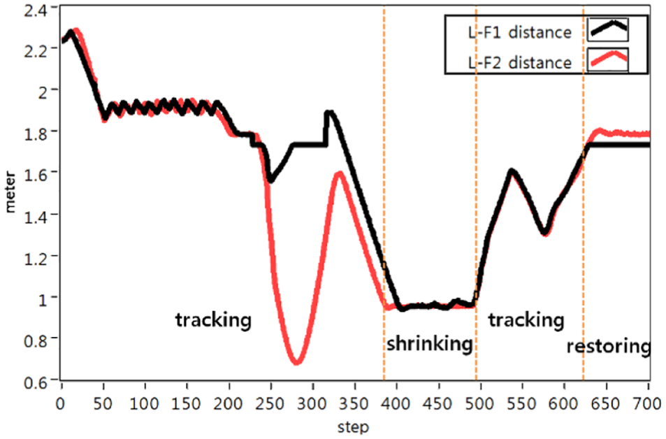
Distance between leader robot and follower robots.

Flexible formation and position switching of robots in real environment.
Conclusion
In this study, we suggested a variable formation control of multiple robots via VRc and formation switching to accommodate large heading changes by leader robot and verified the effectiveness of the proposed algorithm for multi-robot collaboration by grouping. The proposed method consists of three main tasks: formation switching, VRc control, and formation restoration. Through effective formation control, multiple robots act like a single robot. These robots are able to (1) avoid collisions with each other, (2) create and change formations, and (3) decide the best safe plan by determining the shape of an obstacle. Multi-robot formation under communication constraints between robots and complex three-dimensional (3D) environment is undergoing. In future studies, we will conduct intelligent control research and apply the control algorithm not only in group level but also in individual level under moving obstacle environment.
Footnotes
Handling Editor: Xiaoting Rui
Declaration of conflicting interests
The author(s) declared no potential conflicts of interest with respect to the research, authorship, and/or publication of this article.
Funding
The author(s) disclosed receipt of the following financial support for the research, authorship, and/or publication of this article: This work was supported by the 2015 Yeungnam University Research Grant.