
Abstract
In order to improve the drilling efficiency of bit drilling in poor-drillability formation, the authors of this article put forward a cutting–percussion hybrid bit, the fixed-cutting units and impact-crushing units of which are mutually independent and are able to work in parallel. Through finite element analysis, it is concluded that the impact teeth will degenerate the material and mechanical properties of the rock, and that the polycrystalline diamond compact cutters will remove the pre-damaged rock with relatively low energy consumption, thus improving the rock-breaking efficiency of the bit. Moreover, on the basis of the geometrical and kinematical characteristics of the hybrid bit, geometrical relationships between the teeth and the bit body, as well as the kinematics and kinetics of the teeth, are studied in compound coordinate systems. Furthermore, by programming in MATLAB, the rock-breaking process of the hybrid bit is simulated and the simulation results consist of the bottom-hole profile, cutting area, cutting volume, and cutting force of the cutters, providing the theoretical basis for the research and development of the hybrid bit.
Introduction
For deep and ultra-deep wells, the drilling cost of poor-drillability formation accounts for a large proportion in the total drilling cost. More particularly, a low drilling speed in poor-drillability formation has severely affected the construction period and drilling cost of deep and ultra-deep wells. Therefore, improving the drilling speed in poor-drillability formation has become one of the important technical subjects that need to be solved. Among different research branches in this area, drill bit technology innovation is one of the most effective approaches to solve this problem.
In gas and oil well drilling industry, polycrystalline diamond compact (PDC) bit is the most important and widely used among all species of drill bits. Since a PDC bit breaks a bottom-hole rock mainly by scraping and cutting, with superiorities in cutting element performance and rock-breaking method, rock-breaking efficiency of the PDC bit drilling in soft and medium-hard formation is significantly higher than that of a tri-cone bit. Nevertheless, when drilling in hard, high abrasive, or high inhomogeneous formation, even the PDC bit cannot accomplish the rock-breaking task very well. Particularly, if the bottom-hole rock is of high hardness or high strength, it is difficult for the PDC cutter to penetrate the rock and complete a valid cutting process, especially when the cutter is worn after a period of drilling, it will be even more difficult for the cutter to penetrate, accordingly, rate of penetration (ROP) of the bit will be significantly lowered.1–4
On the other hand, down-the-hole (DTH) hammer bit used in rotary percussive drilling is a fixed-tooth rock-breaking tool without moving parts, which is quite similar to the PDC bit in this aspect. In a DTH hammer bit (hereinafter referred to as hammer bit), a series of teeth or inserts (typically are tungsten carbide inserts) are fixed on the bit body so as to cover the bottom-hole rock that will be removed. Above the upper end of the bit body, a hammer is set to provide impact force for the bit. In the drilling process, the hammer is motivated by the drilling medium (drilling fluid or air) to reciprocate so as to impact the upper end of the hammering block continually. With the impulsive impact force obtained from the hammer, teeth or inserts that directly engage with the bottom-hole rock will crush the rock and finally form a wellbore. Nevertheless, due to its structural characteristics, it is usually difficult for the hammer bit to discharge rock debris; moreover, the rock-breaking mode of the bit makes the teeth wear easily or even fracture and fall off the bit body, which is harmful to an efficient drilling process.5–10
The rotary cutting elements in the hybrid bit impact, break, and scrape the rock in a rotating manner, which has the advantages of high breaking efficiency, high ROP, and better kinetic performance; moreover, the structure of the bit bearing is improved to ensure increased rock-breaking efficiency while increasing bit life; different hybrid structure in the hybrid bit can achieve high center rock-breaking performance, high ROP, and fine gauge protection effect.11,12
Aiming at solving the problems existing in PDC bits and hammer bits, the authors of this article put forward a cutting–percussion hybrid bit to improve the ROP of bit drilling in poor-drillability formation. Finite element simulation is utilized in this article to research the rock-breaking mechanism and efficiency of the cutters. On the other hand, velocity, acceleration, and kinetic equations of the hybrid bit cutter are established based on the composite kinematics model, based on which the dynamic rock-breaking process of the hybrid bit is researched by utilizing the numerical simulation method.13–20
Structural characteristics and working principle of the hybrid bit
Structural characteristics of the hybrid bit
As shown in Figure 1, the hybrid bit comprises a bit body, a plurality of fixed-cutting units, impact-crushing units, and a set of hydraulic structures. More specifically, a fixed-cutting unit consists of a wing blade and the PDC cutters fixed thereon, an impact-crushing unit consists of a hammering block, a connector, an impactor, and a plurality of teeth fixed thereon (hereinafter referred to as impact teeth), and the hydraulic structure comprises a plurality of nozzles, flow channels, and junk slots. The fixed-cutting units are fixed on or extended from the bit body, while the impact-crushing units are movably configured on the bit body so that fixed-cutting units and impact-crushing units are mutually independent and are able to work in parallel; besides, the impact-crushing units are distributed in the outer 1/3 radial area of the bit where PDC cutters in the fixed-cutting units are prone to wear.

Schematic drawing of the hybrid bit.
Rock-braking mechanism of the hybrid bit
The rock-breaking process of the hybrid bit is illustrated in Figure 2. First, the impact teeth exert impact force on the bottom-hole rock and simultaneously make pre-damage within the rock, which means that microcracks arisen from different microdefects in the rock will gradually grow and extend under the impact force, thus degenerating the material and mechanical properties of the rock. Then the PDC cutters will scrape the pre-damaged rock and remove it with relatively low energy consumption, which will make the rock-breaking process more effective. Moreover, since the bottom-hole is formed with a plurality of isolated craters made by the impact teeth, the PDC cutters will scrape the rock discontinuously, thus reducing thermal wear of the cutters and further prolonging the service life of the bit.

Rock-breaking process of the hybrid bit.
Technically, the hybrid bit is a rock-breaking tool that has organically combined the fixed-cutting and impact-crushing structures together. On the one hand, the hammer in the impact-crushing unit impacts the hammering block to provide impulsive impact force for the impactor; accordingly, the impact teeth fixed on the impactor will plunge down and crush the bottom-hole rock with a certain frequency. On the other hand, PDC cutters in the fixed-cutting unit will scrape the rock with torque (TOR) and the weight on bit (WOB) obtained from drill string. Based on the scraping and cutting action of the PDC cutters and supplemented with the crushing action of the impact teeth, the rock-breaking mechanism of the hybrid bit can significantly improve the rock-breaking efficiency.
Rock-breaking efficiency of the cutters in the hybrid bit
A DTH hammer bit breaks the rock mainly by crushing that coupled with some grinding action. The impulsive impact force is exerted on the bottom-hole rock in the forms of impact wave and kinetic energy. With an extremely short function time and a high loading rate, the impacting force will result in local stress concentration within the rock near the crushing area. Since there is not enough time for the stress to redistribute, microcracks will arise from microdefects and then grow and extend inside the rock, thus fracturing the rock nearby. Meanwhile, a PDC bit breaks the bottom-hole rock by scraping and cutting the rock with TOR and WOB obtained from the drill string.
Rock failure is a process, in which the hardness of rock decreases continuously and eventually leads to rock failure. The solid line in Figure 3 represents the stress–strain relationship of the damaged material,15–17 while the dotted line represents the stress–strain relationship of the material without damage. Point A is where the damage initiation occurs and the yield stress is

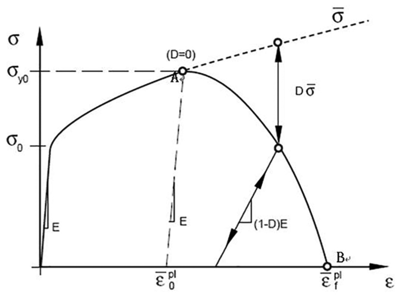
Stress–strain curve of the rock after damage.
The equivalent plastic displacement list function is directly specified as

Aiming at studying the rock-breaking efficiency of the hybrid bit, finite element simulation is utilized and two types of working modes are designed for the cutters to clarify the performance difference of PDC cutters in conventional PDC bit and the hybrid bit. Specifically, as shown in Table 1, working modes in the simulation include the pure cutting mode of the PDC cutter and the impacting–cutting hybrid mode of the combination of the PDC cutter and impact teeth.
Classification of working conditions.
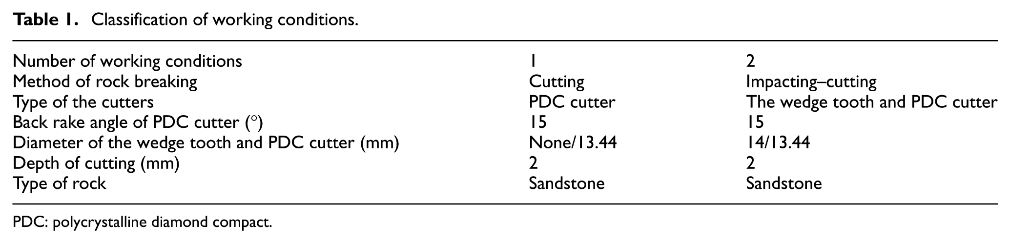
PDC: polycrystalline diamond compact.
In the finite element model, both rock and cutting teeth adopt three-dimensional (3D) eight-node reduced integral element. At the same time, the cutting part of the rock will be refined, the surrounding rock will be gradually thinned, and the contact property between the rock and the cutting teeth will be self-contact. Considering the friction between the cutting surface and rock cuttings and between the flank and cutting surface, the friction coefficient of each contact surface is set. The bottom and side of the rock are defined as infinite non-reflective boundaries, and all degrees of freedom of the bottom of the rock model are constrained. The total additional stiffness control is adopted to make the total hourglass not exceed 10% of the total internal energy of the model. The three degrees of freedom of rotation of X, Y, and Z are fully constrained. The velocity load in the Y direction is 0.2 m/s for the PDC teeth, and that in the Z direction is 10 m/s for the wedge teeth.
The PDC cutters model (Figure 4) used in the simulation is designed with the diameter of Φ13.44 mm and the impact tooth is taken as the wedge tooth of Φ14 mm. On the other hand, the rock constitutive model is set according to Nanchong sandstone (the detailed parameters of which are listed in Table 2). As for the rest of the simulation parameters, the cutting depth is set at 2 mm, the side rake angle of the PDC cutter is 0°, and the back rake angle is 15°. With the same parameters, as shown in Table 3, cutting loads achieved in the simulation and experiment 12 are put together so as to make the following comparisons.

The simulation of cutting teeth broken rock: (a) cutting and (b) impacting–cutting.
Performance parameters of the rock.

Experimental data and simulation results of the PDC cutter cutting rock.

PDC: polycrystalline diamond compact.
It can be seen from Table 3 that when the back rake angle of the PDC cutter is set at 15°, cutting loads achieved from finite element simulation are generally consistent with the experimental results, which means that it is feasible and credible to analyze the rock-breaking process of the PDC cutters with finite element simulation.
The mechanical specific energy is defined as the energy consumed in removing a unit volume of rock, which has been used widely to evaluate the drilling efficiency from the perspective of energy. The breaking volume can be divided into two types: breaking actual volume and breaking projection volume. The breaking projection volume is the product of the breaking projection area and the circumference of the circle at the center of the cutting section. The breaking actual volume is defined as the volume of the removed rock unit. If the breaking actual volume is expressed by the breaking projection volume, the mechanical specific energy is defined as

where W is the breaking work, Vproj is the breaking projection volume, fh is the tangential force, vh is the tangential speed, fn is the axial force, vn is the axial speed, fr is the radial force, vr is the radial speed, and Sproj is the breaking projection area.
Considering the complicated calculation of the breaking actual volume and its little difference with breaking projection volume, the breaking projection volume is adopted to express the mechanical specific energy. Since the projection volume of the rock is the same, the magnitude of the tangential force can be used to represent the mechanical specific energy of the cutter.
Based on this, cutting loads of PDC cutters in both pure cutting mode and impacting–cutting modes are achieved in the simulation. As shown in Table 4, compared with the cutter in the pure cutting mode, both the maximum axial force and maximum cutting force in the impacting–cutting mode are decreased; moreover, the average axial force is decreased by 12.1% (34.93 N), and the average cutting force is decreased by 9.8% (26.09 N). It can be concluded that the impacting–cutting mode can save energy and increase rock-breaking efficiency for the PDC cutters.
Comparison of results from the cutting teeth broken rock simulation.

Figure 5 shows the maximum principal stress in two breaking modes: scraping mode and impact-scraping mode, which indicates that more tensile stress is generated on the rock surface, especially in the impact-scraping cross region in impact-scraping mode, and the scraping mode generates tensile stress but has a low tensile stress. The result shows that the tensile stress in the impact-scraping mode can significantly improve the breaking efficiency and reduce breaking energy consumption.

The maximum principal stress in two breaking modes: (a) cutting and (b) impacting–cutting.
Kinematics and kinetics of the hybrid bit
Geometry and kinematics of the hybrid bit
Geometry of the hybrid bit
To establish the geometric model of the hybrid bit, a cylindrical coordinate system is established for the bit. As illustrated in Figure 6, in the cylindrical coordinate system OθRH, the longitudinal axis OH is constrained to coincide with the central axis of the bit, the orientation of which is along the drilling speed.

The geometric coordinate system of the hybrid bit.
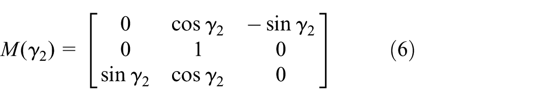
Furthermore, in the local rectangular coordinate system of a PDC cutter, take the coordinates of a certain point P in the cutter as (Xp2,Yp2,Zp2); on the other hand, in the cylindrical coordinate system of the hybrid bit, take coordinates of the center point O2 of the cutter as (R2,θ2,H2). Geometrically, with several transfer matrices, coordinates of point P(Xp2,Yp2,Zp2) can be transferred from the local rectangular coordinate system of the cutter into the cylindrical coordinate system of the bit. The transfer matrices are given by equations (4)–(7), where M(ξ2) is the transfer matrix to the back rake angle coordinate system, M(δ2) is the transfer matrix to the side rake angle coordinate system, M(γ2) is the transfer matrix to the normal angle coordinate system, and M(θ2) is the transfer matrix to the cylindrical coordinate system of the bit


In the above equations,
With these transfer matrices, transformation of the coordinates of point P from the local rectangular coordinate system to the rectangular coordinate system of the bit could be derived as
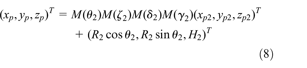
Furthermore, coordinates of point P in the rectangular coordinate system of the bit can be transformed into the cylindrical coordinate system, which are

On the other hand, in the local rectangular coordinate system of an impact tooth, take the coordinates of a certain point N in the cutter as (Xn1,Yn1,Zn1), while, in the cylindrical coordinate system of the hybrid bit, take coordinates of the center point O1 of the tooth as (R1,θ1,H1). Geometrically, with several transfer matrices, coordinates of point N(Xn1,Yn1,Zn1) can be transferred from the local rectangular coordinate system of the tooth into the cylindrical coordinate system of the bit. The transfer matrices are given by equations (10)–(12), where M(γc1) is the transfer matrix to the inclination angle coordinate system of the tooth, M(γ1) is the transfer matrix to the inclination angle coordinate system of the impactor where the tooth mounted, and M(δ1) is the transfer matrix to the cylindrical coordinate system of the bit
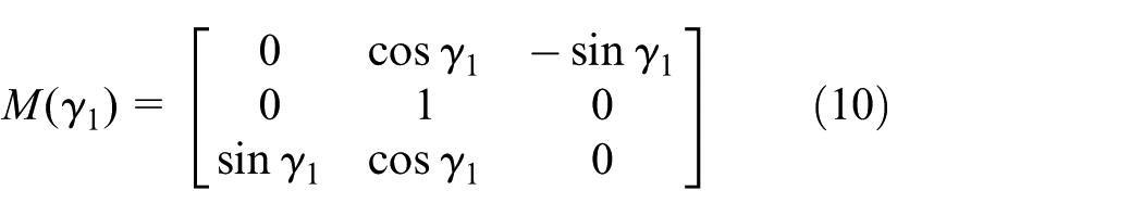


where γc1 represents the inclination angle of the tooth, while γ1 represents the inclination angle of the impactor where the tooth mounted.
With these transfer matrices, the transformation of the coordinates of point N from the local rectangular coordinate system to the rectangular coordinate system of the bit could be derived as

Furthermore, coordinates of point N in the rectangular coordinate system of the bit can be transformed into the cylindrical coordinate system, which are

Equations (9) and (14) together are geometric equations of the hybrid bit.
Kinematics of the hybrid bit
For PDC cutters, since the cutters are fixed on the wing blade which is fixed on or extends from the bit body, during the drilling process of the hybrid bit, PDC cutters will not rotate or move relative to the bit body, and they will just revolve around the bit axis as the bit drills. Take VZrop as the drilling speed of the bit and ω1 as the angular velocity of the bit. And for a certain PDC cutter, assume VZM as the moving speed (along the bit axis OZ) of a certain point M in the cutter, VRM as the radial velocity, and VτM as the rotational linear velocity of the point. Then, the absolute velocity of the point M is the vector sum of VZM and VτM

where RM is the radius of point M in the cylindrical coordinate system of the bit, and it should be noted that
Through taking the derivatives of VZM and VτM with respect to the time factor t, the acceleration equations will be derived as follows. It should be noted that aRM is the centripetal acceleration of point M

On the other hand, for the situation of certain impact tooth, a certain point Q in the tooth not only revolves around the bit axis and simultaneously moves along the drilling direction (as the PDC cutter does), but will also periodically reciprocate under the periodic impact force achieved from the hammer.
Specifically, the process that the impact teeth motivated by the hammer could be represented as (ignoring the influence of such factors as impactor and hammering block)

where m1 (kg) is the mass of the hammer, m2 (kg) is the mass of all the impact teeth, v0 (m/s) is the velocity of the hammer before impacting the impactor, v1 (m/s) is the velocity of the hammer after the impacting, v2 (m/s) is the velocity of the teeth after the impacting, and b is the rebound velocity coefficient of the hammer after the impacting.
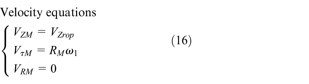
For the point Q, the velocity equations are

and the acceleration equations are
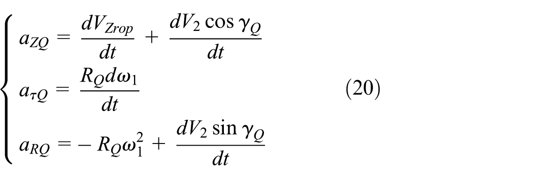
where RQ is the radius of point Q in the cylindrical coordinate system and γQ is the equivalent angle between point Q and axis OH in the cylindrical coordinate system.
If no impact force is exerted on the teeth, velocity and acceleration of point Q should be the same as those of point M mentioned above.
In this situation, the velocity equations of point Q should be

and the acceleration equations should be

Kinetics of the hybrid bit
During the drilling process of the impact-crushing unit, which is quite similar to the DTH hammer bit, the hammer is motivated by the drilling medium (drilling fluid or air) to reciprocate so as to impact the upper end of the hammering block continually. With the impulsive impact force obtained from the hammer, the impact teeth penetrate and crush the rock. For the penetrating procedure, the differential equation is 6

By substituting the initial variables and solving the above equation, the solution can be derived as 7

where P represents the penetrating force, P(t) represents the incident stress wave, K is the penetrating coefficient, m1 is the mass of the hammer, m2 is the mass of the impacting teeth, φ is a dimensionless quantity, which values the situation of the whole impact-crushing process, and is also known as penetrating-crushing index, and V2 is the impacting velocity of the teeth.
By taking the derivative of P with respect to the time factor t and making the equation equal to zero, the maximum position and maximum value of the penetrating force could be obtained as
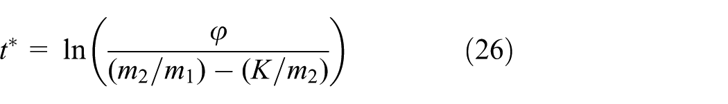

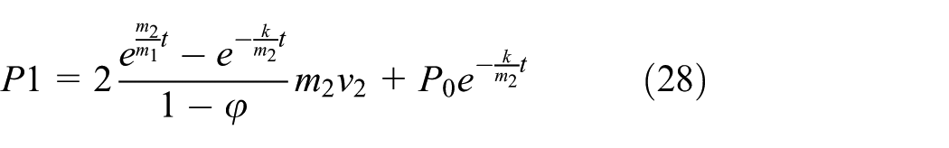
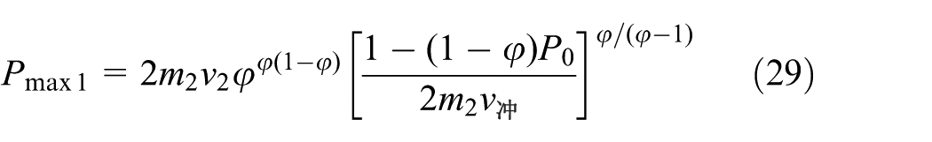
In a general drilling process, a static pressure P0 is exerted on the bit body, so the initial variables should be t = 0 and P = P0. By substituting the variables into the equations, the penetrating force and its maximum value are obtained as
Propagation of stress wave in the impactor contains all the energy achieved from the hammer. For a certain particle in the impactor, the energy W consists of two parts, that is, the elastic strain energy W1 and the kinetic energy W2

Furthermore, for the elastic strain energy W1 and kinetic energy W2
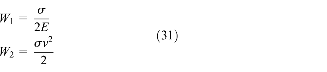
where σ is the stress, E is the elastic modulus, ρ is the density, and v is the velocity of the particle. These factors could further be expressed as


where a (m/s2) is the acceleration of the particle. On the basis of equations (30)–(32), equation (28) is transformed as
Accordingly, equation (27) should be transformed as

For the total energy contained in the impactor, it is the integral of W along the stress wave distribution in the impactor
where F (m2) is the cross-sectional area of the impactor.
Take P as the force exerted on a certain cross-section of the impactor and v as the velocity of the particle in the section, then Pvdt is the work produced in the time period dt by the force P. Obviously, the total energy contained in the impactor is the integral of Pv over the time factor t

When analyzing the impact force in the impactor, the model is simplified as a long circular section column. In other words, if an impact force is exerted on one end of the model, particles in the end face will vibrate immediately and the vibration will propagate along the axis of the column. For a short segment dx of the column, assuming A as the cross-section area, ρ as the material density, and σx as the stress in the first cross-section P of the segment, then the stress in the second cross-section Q should be

According to Hooke’s law
Through substituting equation (40) into equation (39), the equation can be transformed as

Equation (39) is the kinematic equation about the displacement u, and it can further be transformed as

where
For equation (39), the general solution is

where
Furthermore, take the partial derivative of

And take the partial derivative of

Since
Since
Accordingly

Obviously, velocity v of the particle is directly proportional to the stress σ.
Dynamic simulation for the rock-breaking process of the hybrid bit
Digitalization of the simulation system
The cutting teeth are objects that interact directly with the rock, so the quality of the discrete mass has a great influence on the calculation efficiency and calculation accuracy. Its dispersion includes the tooth surface and the tooth flank. The right-angle-equal arc length discretization method integrates advantages of the equal-spacing discretization method and the polar coordinate method: the tooth edge nodes are evenly distributed and the node density of the tooth surface involved in cutting is larger than that of the central area not involved in cutting (Figure 7). The coordinates of the digital node

where R is the radius of the cutter and

Discrete model of cutting tooth.
The 3D distribution of node rocks is to discrete the rocks in three directions of space. Taking the centroid of the upper surface of the rock as the origin, the coordinate axes x, y, and z are, respectively, along the direction of the length, width, and height. In the coordinate system OXYZ, the rock is equally spaced by a plane beam parallel to the three coordinate axes, and every three orthogonal planes form an intersection point, which is a digitized node, and the discrete model is

where a, b, and c are the length, width, and height of rocks, respectively; lx, ly, and lz are the discrete steps in the X, Y, and Z directions, respectively. Figure 8 shows the discrete model of rocks.

Discrete model of rocks.
On the basis of the geometric, kinematic, and dynamic equations of the mixed bit, the authors complete the dynamic simulation for the rock-breaking process of the hybrid bit in MATLAB. The digital drilling simulation system for cross-cutting PDC bit is based on MATLAB, and each physical object is characterized by data points. Before drilling simulation, both the positional relationship among the data points of each cutting unit of the bit and the positional relationship among data points of the bit and the rock data points must be established, which is the drilling initialization. Then the PDC bit is moved to the rock surface, and the bit axis is coincided with the rock axis. The bit is set to revolve around the axis and drill in the positive direction of the axis.
Drilling simulation result analysis
In the simulation system, the pre-input parameters such as rock density, compressive strength, Poisson’s ratio, impact energy, and impact frequency are required. Then, the cutter parameters are imported to the simulation system (Table 5).
Cutter parameters.

In the dynamic simulation for the rock-breaking process, the hybrid bit and bottom-hole rock are taken as the main simulation objects. For the hybrid bit, since only the PDC cutters and impact teeth directly contact the bottom-hole rock, the bit model is simplified as the combination of the PDC cutter model and the impact teeth model, as shown in Figure 9. Furthermore, considering the structural characteristics, the rock model is idealized as a series of equally spaced discretized nodes (as illustrated in Figure 10); accordingly, the cutters and teeth models are also idealized as discretized nodes so as to realize the interaction with the rock model.

Discretized model of the hybrid bit.

Simulation outcome of the bottom-hole rock.
On the other hand, since the position of each cutter or tooth is a continuous variable over time, the rock-breaking process (as illustrated in Figure 11) of the bit is a continuous process.

Rock-breaking process of the cutters: (a) PDC cutter and (b) impact teeth.
As the basic scheme of the simulation, the time period of rock breaking is divided into many equal time intervals (i.e. time steps). With certain time step density, the continuous process is naturally transformed into a discretized one. For every time step, the simulation system will calculate and regenerate the status of the cutters, teeth, and rock; simultaneously, the status data (including positions, contacting area, forces of the cutter, drilling speed, WOB, and TOR of the bit and bottom-hole profile) will be recorded and the bottom-hole will be reshaped. When the simulation is finished, all the data will be gathered to analyze the rock-breaking process.
The velocity and energy on the impact cutters are calculated from the input impact energy and impact frequency. The contact area between the cutters and the rock is obtained by the interaction between the cutters and the rock (Figure 12).

Contact area of cutting teeth: (a) PDC cutter and (b) impact teeth.
It can be concluded from the simulation results that the rock-breaking process of the hybrid bit cannot simply be evaluated by drilling speed; it should be analyzed with mechanical parameters in the drilling process. On the basis of the geometry, kinematics, kinetics, and cutting mechanics of the hybrid bit, cutting area, cutting volume, and cutting force of the cutters and teeth on the bit (as illustrated in Figures 13 and 14) are obtained from the rock-breaking simulation in MATLAB, which is further used to evaluate the rock-breaking performance of the hybrid bit. Some parameters are obtained from the simulation, such as the cutting section of the cutting tooth, cutting volume, stress situation, and torque. The cutting section and cutting volume of the cutting teeth are observed, and it is necessary to rearrange the cutting teeth if the cutting volumes of the cutting teeth differ too much due to the reason that the cutting teeth at the external one-third cutting area have a high line speed, thus facing with a high impact load. The stress situation and the torque of the cutting teeth are observed. The force on the cutting teeth should decrease from the center to the edge. The force and torque of each cutting tooth are concentrated on the hybrid bit, so that the unbalanced force of the hybrid bit can be controlled within 5% of WOB, which will help improve the stability of the hybrid bit.

The cutting volume of cutter.
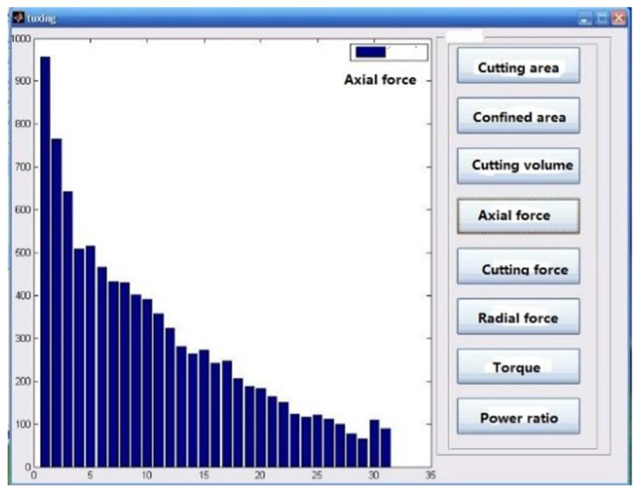
The axial force of cutter.
Conclusion
Aiming at improving the drilling efficiency of the bits drilling in poor-drillability formation, the authors of this article put forward a cutting–percussion hybrid bit, the fixed-cutting units and impact-crushing units of which are mutually independent and are able to work in parallel. With the special structure, WOB is substantially exerted on PDC cutters, which will improve the penetrating ability for the fixed-cutting unit. On the other hand, since the impact load is generally taken by the impact-crushing unit that makes isolated craters in the bottom-hole, there is nearly no load fluctuation on the PDC cutting unit, which will protect the PDC cutters from fracturing or falling off the bit.
Finite element simulation results show that the rock-breaking method of impacting and cutting will obviously lower the specific energy consumption of the PDC cutters, thus improving the rock-breaking efficiency of the cutters. On the other hand, pre-damages by impact teeth, material, and mechanical properties of the rock are degenerated, which is beneficial to the drilling efficiency.
Dynamic simulation is conducted in MATLAB to clarify the rock-breaking process of the hybrid bit. In the simulation, volume and force of the cutters are calculated and analyzed, and the bottom-hole profile shaped by the hybrid bit is obtained to show the rock-breaking process intuitively. The output parameters can guide the PDC cutter designing of the hybrid bit so that the unbalanced force of the hybrid bit can be controlled within 5% of ROP, which will help improve the stability of the hybrid bit.
Footnotes
Appendix 1
Handling Editor: Jianbo Yu
Declaration of conflicting interests
The author(s) declared no potential conflicts of interest with respect to the research, authorship, and/or publication of this article.
Funding
The author(s) disclosed receipt of the following financial support for the research, authorship, and/or publication of this article: This work was supported by the Research Program of National Natural Science Foundation of China (grant no. 51374176).