
Abstract
Aiming at improving the ROP of PDC bits in hard-to-drill formation, a new hybrid PDC bit with vertical-wheel is proposed in this paper, furtherly, the kinematic characteristics of the vertical-wheel are researched. Firstly, the coordinate system of the vertical-wheel is established, on basis of which the motion equation, the speed equation and the acceleration equation of the vertical-wheel is derived. Secondly, a series of unit rock-breaking experiments on the vertical-wheel with variable parameters are carried out, so that the average speed of vertical-wheel under different conditions is obtained and the theoretical model of average speed is established, furthermore, the influence of diameter and normal angle of the wheel on the average speed is analyzed. Thirdly, the speed of vertical-wheel under different conditions is measured on basis of the speed model with compensation coefficient, specifically, the calculated average speed of the Ø18 mm vertical-wheel according to the instantaneous speed model is 4.532 r/s, while the average speed obtained in experiment is 4.491 r/s, with an error of 0.9%, proving that the measuring method and modeling of the instantaneous speed are credible. Lastly, the theoretical conditions for continuous rotation of the wheel are obtained. The research results are of great significance to study the working mechanism of the vertical-wheel and provide technical support for the application of the hybrid PDC bit with vertical-wheels.
Keywords
Introduction to the vertical-wheel hybrid PDC bit
Since most undeveloped oil and gas resources in China are buried in deep strata,1–3 and steering drilling (including horizontal well drilling) technology can greatly improve oil and gas production and reduce the comprehensive cost of oil and gas development, deep and ultra-deep well drilling and directional well drilling are the key technologies for oil and gas resource development in the future. In deep or ultra-deep formation, the effects of overburden pressure and fluid pressure increase the rock strength and make the bottom-hole rock hard to drill. In addition, due to insufficient hydraulic energy and long tripping time, low drilling efficiency and high drilling cost become problems that need to be solved urgently.4–8 In steering drilling, the rock-breaking behavior of the bit in the bottom-hole is much more complex than that of conventional drilling.9–12
PDC (Polycrystalline Diamond Compact) bit is the most widely used drill bit in oil and gas drilling, and its drilling footage has reached more than 94% of the total drilling footage in the world. 13 Various and complex drilling conditions has posed more and severe challenges to PDC bit technology. In spite of improving the performance of PDC cutters, reducing and stabilizing the torque of the bit is also necessary, which including improving the anti-stick-slip performance and developing steering drilling performance of the bit. Moreover, it should be noticed that buffer protection for PDC cutters can greatly improve the service life of cutters, and that auxiliary cutting structure for pre-rock-breaking can prolong the service life of cutters.
On basis of these ideas, Baker Hughes has developed the KymeraTM hybrid PDC bits, 14 including the Kymera FSR series, as shown in Figure 1 (left), and the Kymera XTreme series, as shown in Figure 1 (right). Each Kymera hybrid PDC bit consists several fixed wing-blades and a plurality of rotatable cones. Field application shows that the combination of these two rock-breaking structures can restrain the stick-slip behavior and develop the steering drilling performance for the bit in complex drilling conditions. On the other hand, Halliburton Company has invented the CruzerTM PDC bits, 15 as shown in Figure 2, each Cruzer PDC bit is configured with several small rollers behind the PDC cutters. Although the supporting structure and the bearing system of the roller tend to break easily, these rollers can theoretically improve the steering drilling performance of the bit and protect cutters by restricting the cutting depth. The application results shows that the hybrid structure has improved the drilling speed of the bit and prolonged the service life of the cutters thereon.

Kymera FSR (left) and Xtreme (right) hybrid PDC bits of Baker Hughes.

Cruzer hybrid PDC bit of Halliburton.
These researches have innovated the structures of the PDC bit. The vertical wheel, as mentioned above, is generally a cylindrical rock-breaking structure configured with a circle of teeth in the crown and with integrated shafts thereunder. By setting a series of vertical wheels on the wing-blades of the PDC bit, a new vertical-wheel hybrid PDC bit is formed, as shown in Figure 3. The vertical wheel (hereinafter referred to as wheel), on one hand, rotates around its own axis, and simultaneously revolves around the bit axis, thus forming a compound motion which is a little bit similar to the cone in a tri-cone bit, but the actual motion behavior of the wheel is quite different from the cone. The vertical wheel is disposed on the drill bit as a multifunction rock-breaking structure. First, it is an auxiliary rock-breaking structure that pre-fracture bottom-hole rock for the PDC cutters to improve penetrating capacity of the cutters; Second, friction and cutting resistance from the rock may result in fluctuation on the instantaneous speed, but if the bearing system and other geometric parameters (size, location and direction etc.) are well designed, the rotation of the wheel will not be stopped, thus lowering the torque response and reduces the stick-slip behavior of the bit, which is beneficial to the working capacity of PDC bit in steering drilling; Third, it is also a buffer for PDC cutters that protecting the cutters from impact load and WOB fluctuation, thus prolonging service life of the cutters.
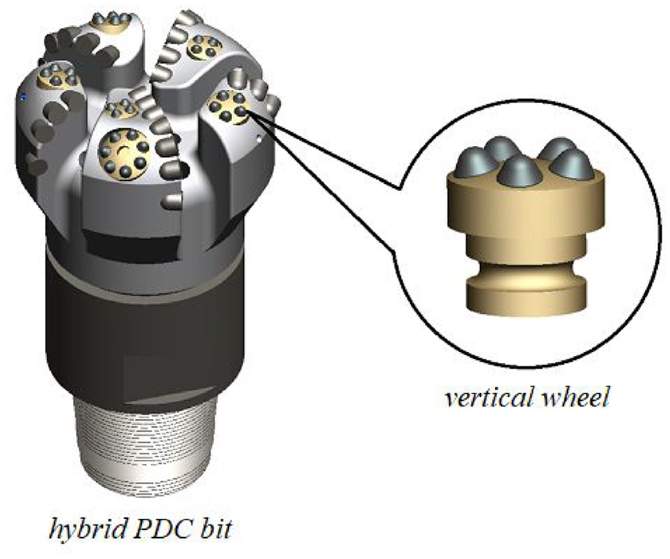
Vertical wheel hybrid PDC bit.
The vertical-wheel hybrid PDC bit is an organic combination of two sets of cutting structures with different motion modes, that is, the fixed cutting structure (the wing-blades and the PDC cutters fixed thereon) and the vertical-wheel. The kinematic mechanism of fixed cutting structure can be obtained through the existing literature.16–19 Since the vertical-wheel is a new structure, it is necessary to study the kinematic characteristics of it so that the rock-breaking mechanism of the hybrid PDC bit can be revealed.
Kinematics theory of the vertical-wheel
Coordinates of the vertical-wheel
Since the wheel rotates along its own axis when the bit body revolves, the motion of the wheel is a compound motion, so that the coordinate system of the wheel should be established as a compound system, as shown in Figure 4, wherein, Figure 4(d) briefly shows the relationship of spatial positions between the bit and the wheel, Figure 4(a) is a detailed upward view of Figure 4(d), so that the bit rotates clockwise in this view. Figure 4(c) is aligned with Figure 4(a) and shows the local rotating coordinate system of the wheel together with Figure 4(b). In order to clarify the coordinate systems, points, angles, and line segments in these figures are marked in blue, the rotating axis of the wheel is marked in red and the other elements are black.

Coordinate systems of the bit body and the wheel.
First is the coordinate system of the bit, which is defined as a cylindrical-coordinate system. As shown in Figure 4(d), point O is a certain point on the revolving axis of the bit, it is taken as the origin of the coordinate system, and the plane passes through the point and simultaneously perpendicular to the bit axis is defined as the reference plane of the bit. By taking axis OH (which is aligned with the bit revolving axis) as the longitudinal axis, OX (which is a certain radial axis perpendicular to the longitudinal axis) as the polar axis and
On the other hand, since the wheel will rotate along its own axis when the bit revolves, it is necessary to establish a rotating system for the points on it. As shown in Figure 4(b) and (c), take the vertex point Q(
Additionally, in the rotating coordinate system of the wheel, point O′ is the intersection point of line OWOQ and the reference plane, and axis O’H′ is parallel to the axis OH, the angle between OWOQ and O′H′ is the normal angle of the wheel, as shown in Figure 4(c). Considering that point O can move along the bit axis, if the distance between O and O′ equals to the offset s, axis O′H′ must be a vertical projection of axis OH on the wheel polar plane. As shown in Figure 4(a) and (d), line OX0 is a line parallel to the wheel polar plane, if the plane X0OH is taken as the feature plane of bit revolving, then the angle
According to Professor Ma Dekun’s theory, 20 the position or coordinates of point Q in the bit coordinate system can be expressed as:

Wherein,

Speed equation of vertical wheel
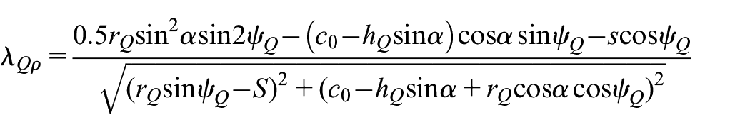
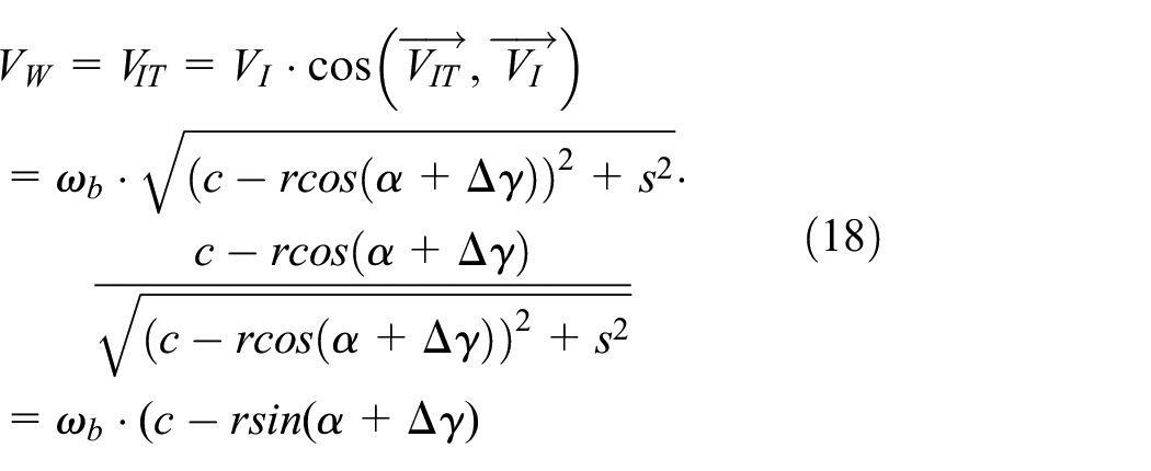
According to the radius vector
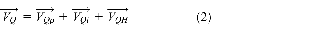
Apparently, the derivative of radius vector of point Q with respect to time is the radial component


Wherein,

Wherein,
Acceleration equation of vertical wheel
The speed components of VQ obtained above is perpendicular to each other in the axial, radial and tangential directions, and their respective acceleration and Coriolis acceleration are homogeneous in these three directions. Therefore, the acceleration of point Q can be divided into three acceleration components: axial
The axial acceleration

Wherein,
The radial acceleration

Then the radial acceleration

Where

And,


Wherein, G’ is the derivative of G,
The tangential acceleration also includes two parts, one is the tangential acceleration


Thus, the tangential acceleration
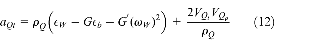
Where
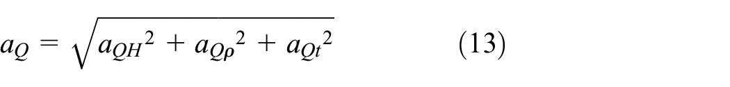
Therefore, the acceleration expression of point Q is:
Trajectory equation of vertical wheel
Assuming that the feature point is the vertex of a certain tooth on the wheel, then the coordinates of the wheel tooth
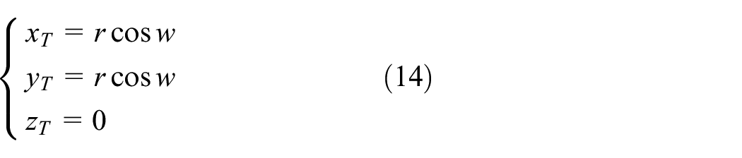
Where
Through coordinates conversion,

Assuming that
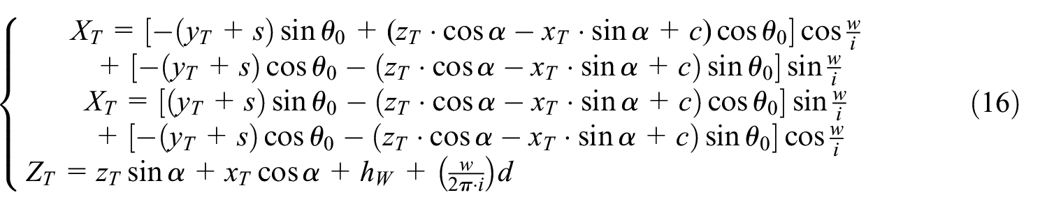
Where
Calculation of wheel/bit speed ratio
The ratio between the rotation speed of the wheel and revolution speed of the bit body is called the wheel/bit speed ratio, it is very important for kinematics analyzing, bearing system designing, and anti-wear performance of the bit.
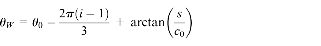
On the feature plane of the bit, as the plane X0OH shown in Figure 4, the wheel can be vertically projected on the polar plane of the bit body. In the projection view, the teeth-disposing circle should be a line segment, as the dashed and solid line segments shown in Figure 5 (left). If profile of the wheel (hereinafter referred to as wheel profile) perfectly matches with the cutting profile of the bit, the normal angle is defined as the original normal angle

Wherein,
So that the wheel/ bit speed ratio should be:

It should be noted that the deviation angle


Normal angle (left) and speed decomposition of the wheel (right).
Measuring and modeling for average speed of the vertical wheel
Measuring and modeling for average speed of the vertical wheel
The average speed of the vertical wheel is measured during the unit rock-breaking experiment on the wheel. As shown in Figure 6, the experiment is carried out on a planning machine which is specially developed to be suitable for unit rock-breaking experiment. The experiment equipment mainly includes the planning machine, feeding speed adjusting module, penetrating depth adjusting module, tri-axial load transducer, rock sample fixture, data acquisition system, and high-speed camera. Limited by the dimensions of the rock sample fixture, the rock sample used in this experiment is a sandstone in the volume of 280 mm × 280 mm × 160 mm. Specifically, the wheel is rotatably mounted on the wheel seat through an integrated shaft, as shown in Figure 9 (right) in the following content, both the wheel shaft and the wheel seat are manufactured with grooves for rollers, and a plurality of rollers are put in the grooves through a hole on the seat, so that the wheel is enabled to rotate and is prevented to fall from the seat. Besides, a thrust bearing is configured at the back end of the wheel shaft to reduce friction. The fitting depth of the wheel can be adjusted by applying different thrust bearings and wheels, and the normal angle of the wheel can be adjusted by changing the mounting angle between the transducer and the wheel seat.

Experiment equipment (left) and the wheels (right).
For the unit rock-breaking experiment, the experimental principle is that when the cutting teeth of the wheel contact with and start to penetrate in the rock, there will be an impact load between the teeth and the rock. On one hand, the impact load on the rock will break the rock, on the other, the cutting force (tangential force) on the wheel will increase and the angular speed will decrease sharply, which can be indicated by the force peak in the cutting force curve. Accordingly, a valley bottom will appear on the wheel angular speed curve. Therefore, in the whole rock-breaking process, the instantaneous angular speed of the wheel changes periodically as the wheel rotates, and the number of peaks (or valleys) on the curve is equal to the impacting times of the teeth penetrating in the rock. As shown in Figure 7, the curve shows the variation of tangential force of the wheel with its diameter being Ø30 mm, particularly, it is mounted with conical teeth and the normal angle is 15°. It can be seen from the curve that 16 peaks are produced totally, respectively, the total number of the rock-breaking tracks (or scratches) generated by the wheel are 16, as illustrated in the red box in Figure 8.

Variation of tangential force on the wheel with respect of time.

Scratches formed by the vertical wheel.
The experimental average speed
Where,
This experiment is carried out with variable parameters, which including different wheel diameters, normal angles, back rake angles, tooth profiles, height-diameter ratio and different cutting depth. Furthermore, each experiment is repeated for three times. Particularly,
Wheel diameter D:
Normal deviation angle
The back rake angle of the wheel: 0°, 5°, 10°, and 15°, the definition of back rake angle of the wheel is similar to the normal deviation angle, the difference is that its deviation direction is perpendicular to the paper inwardly or outwardly at the position shown in Figure 9 (left);
Tooth profile: conical tooth, wedge tooth, circular section tooth and conical section tooth;
Both the normal deviation angle and back rake angle exist: the normal deviation angle is 15°, and the back rake angle is 10°;
Height-diameter ratio HW/D of the wheel: 3, 2, 1, as shown in Figure 9 (right), wherein, HW is the exposing height of the wheel;
Depth-diameter ratio (S / D): 1, 1/2, 1/3, wherein, S is the fitting depth of the wheel shaft;
Cutting depth of wheel: 1 mm, 1.5 mm, 2 mm.
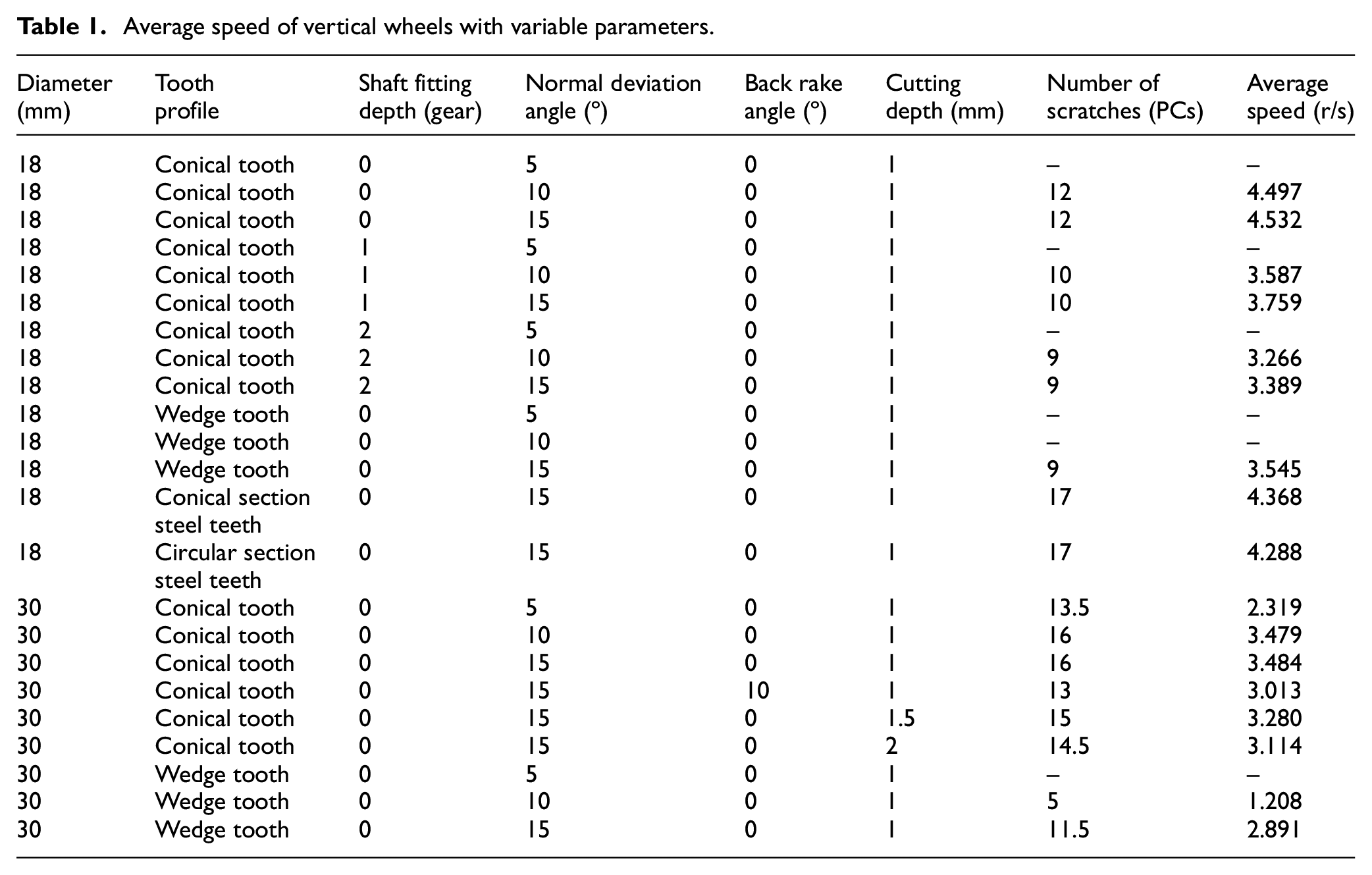
According to the experiment, the experimental average velocities of the wheels are obtained, as shown in Table 1.
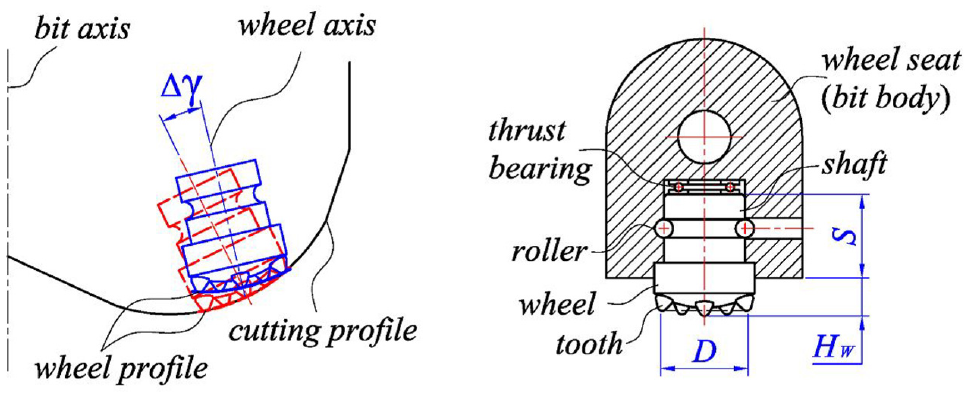
Definition of normal deviation angle (left) and matching relationship between wheel and wheel seat (right).
Average speed of vertical wheels with variable parameters.
By analyzing and fitting the rotating speed of different wheels in the experiment, the fitting result can be concluded that the rotating speed

Where:
Analysis on factors affecting the average speed of vertical wheel
Influence of wheel size
Firstly, the wheel itself has two main dimensions, one is the radius r of the wheel, which is the distance from the tooth edge to the central axis of the wheel, and the other is the radius R of the teeth-disposing circle.
According to the average speed equation of the wheel, the speed ratio i of the wheel body is inversely proportional to
Under the condition of the same wheel radius r (i.e.

Wheel profiles with different teeth disposing radii and normal deviation angles.
Apparently, the teeth disposing radius of the wheel 3# shown in Figure 10 is larger than the radius of the cutting profile of the drill bit. In this case, if the wheel has no normal deviation angle, at least one side of the wheel will be exposed higher than the cutting profile of the drill bit, so that the cutting teeth on the wheel will no longer cut the rock alternatively, instead, all the teeth will contact with the rock continuously.
Influence of normal deviation angle of the wheel
According to the average speed equation of the wheel, the variation relationship between the average speed and the normal deviation angle is a sinusoidal function. Since the normal deviation angle of the wheel is generally set in the range of 10°–30°, it can be considered that the greater the normal deviation angle, the greater the average speed of the wheel. Then, in order to improve the service life of the wheel bearing, the normal deviation angle of the wheel should be set smaller; however, when the normal deviation angle decreases, especially when it approaches zero, the teeth will slide on the rock more obviously, so that the interaction time between the contacting tooth and the rock will be prolonged, thus, two or more teeth will cut the rock at the same time, which will accelerate the wear of the teeth. Therefore, the normal deviation angle should be reasonably designed according to specific application requirements for the bit.
Instantaneous speed and speed compensation for the vertical wheel
Compensation method for the rotating speed
Compared with the instantaneous speed, it is relatively easier to measure the average speed of the wheel, because the average speed can be obtained by counting the number of the teeth on the wheel and the scratches formed on the rock. The average speed can be used to calculate the wheel/bit speed ratio, and furtherly calculate the drilling speed and tooth wear of the bit. However, in fact, the rotation speed of the wheel is non-uniform. Additionally, due to the flexibility of the drill string, the revolution speed of the bit body in actual drilling condition is also not uniform. To study the dynamic load of the wheel in rock-breaking process, the instantaneous speed of the wheel is required.
Since the instantaneous speed of the planning machine is not uniform, before measuring the instantaneous speed of the wheel, the instantaneous speed of the planning machine must be corrected. By fixing a ruler on the rock sample, as shown in Figure 11 (left), the position of the wheel along the moving direction can be directly taken by the high-speed camera. In order to measure the instantaneous speed of the wheel, the cylindrical surface of the wheel is divided by marked degrees thereon, and the speed of the wheel is approximately calculated by the position taken in each picture collected by the high-speed camera. As shown in Figure 11 (right), each interval represents 2º. Thus, the approximate instantaneous speed can be measured by the angle variation of wheel on timeline.

Planning machine with ruler (left) and wheels with measuring intervals (right).
Speed compensation coefficient and instantaneous speed model
Through data processing on the collected position of the planning machine, the moving speed of the machine can be calculated. It should be noted that random rock breakage usually occurs at the start and end point during the contacting process, the actual contacting length is shorter than the rock length (280 mm). Under the moving speed of the planning machine, the effective contacting time between the wheel and the rock is around 0.7 s, as a result, the time range of effective data acquisition is 0–0.7 s. During the experiment process, the position of the planning machine is recorded by the high-speed camera, so that the moving distance of the machine in each time interval can be achieved by comparing the position and time point in recorded frames. Through dividing the distance by time interval in adjacent frames, the instantaneous speed can be calculated. As shown in Figure 12, each blue box represents an instantaneous speed point on the time line. Considering the data variation trend, polynomial fitting method is applied to fit the instantaneous speed model. As the blue curve shown in Figure 12, the speed equation of the planning machine is derived as a quadratic polynomial, for the fitted speed

When calculating the rotating speed of the wheel, the influence of the planning machine speed should be taken into consideration. It can be observed in Figure 12 that the instantaneous speed of the planning machine gradually decreases form the start point, accordingly, if the speed of the planning machine is a constant value, the wheel should rotate faster than it is observed. As a result, the instantaneous speed compensation coefficient

Where

By recording the rock-breaking process of the wheel and comparing the angular position of the wheel frame by frame, the instantaneous rotation speed can be calculated. And furtherly, with the speed compensation coefficient, the instantaneous rotation speed is corrected, as shown in Figure 14, it can be found that the instantaneous speed variation is substantially a sinusoidal function in timeline. Among all the tested wheels, the rotating speed of the wheel with a diameter of 18 mm is unstable and fluctuates widely, while the rotating speed of the wheel with a diameter of 30 mm is relatively stable. The average speed of φ18 mm wheel calculated according to equation (18) and corrected according to equation (25) is 4.532 r/s, while the average speed obtained according to the collected pictures is 4.491 r/s, with an error of 0.9%, indicating that the compensation for the speed model is reliable.

Speed fitting of planning machine.

Numerical fitting for the speed compensation coefficient.
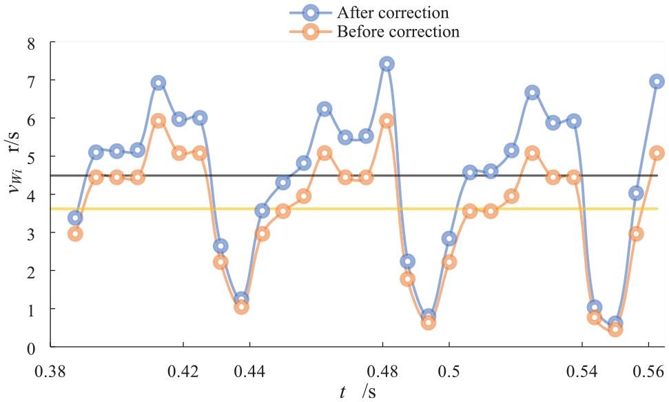
Instantaneous and average speed of the φ18 mm wheel.
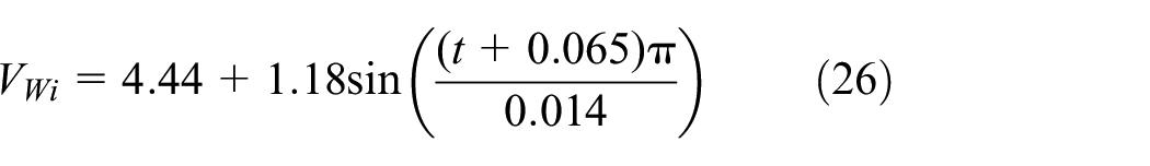
For the wheel with a diameter of 18 mm, considering the compensation coefficient, the theoretical model of instantaneous rotating speed
Conditions for continuous rotation of vertical wheel
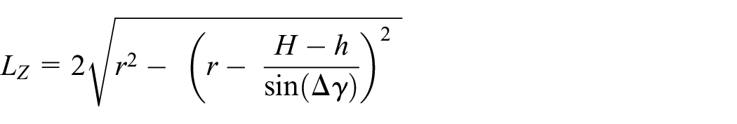
In the actual drilling process, the interaction between the teeth and the rock is a dynamic process. With a certain tooth spacing, the wheel can keep rotating as long as the normal deviation angle is large enough. Ideally, the friction on the shaft is small enough so that it can be ignored when the wheel rotates. In this condition, the tooth arrangement should satisfy the requirement that at least one tooth contact with the rock at the same time, that is, if the former tooth leaves the rock, at least one tooth is still in contact with or is contacting the rock. Therefore, the maximum teeth spacing can be represented as:

Where,
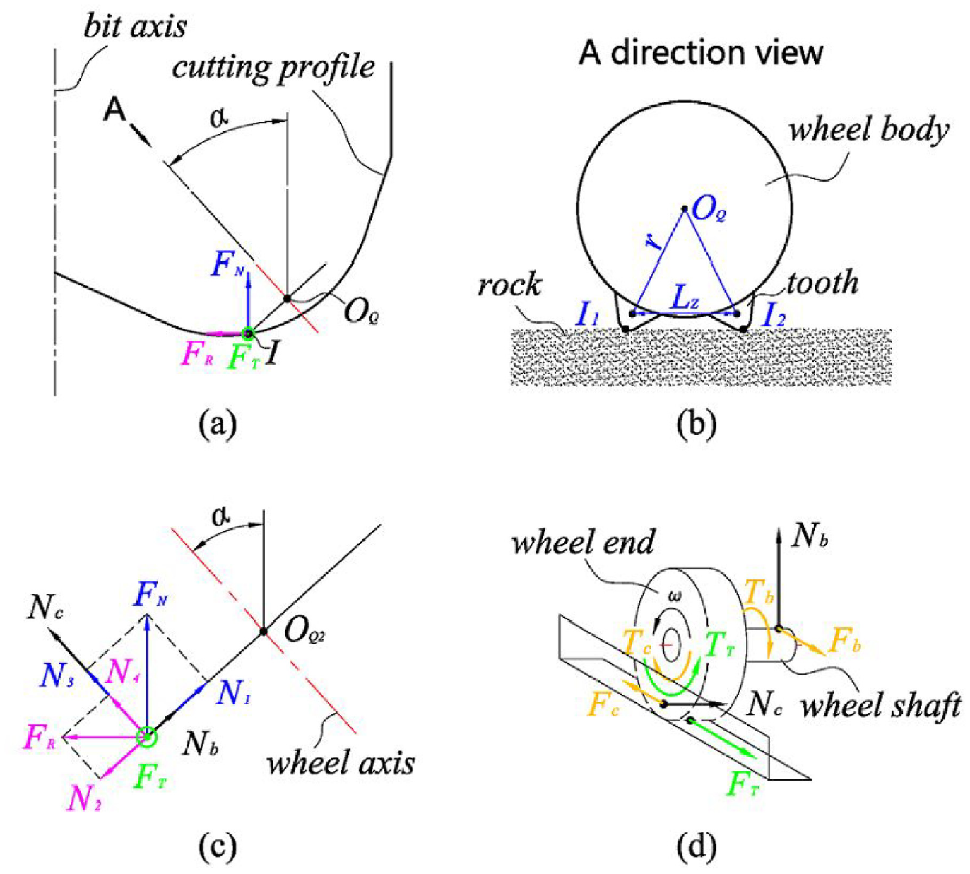
Force diagram on the wheel and its A-direction view.
In the ideal condition, as long as the actual teeth spacing L on the wheel is smaller than
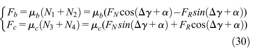
In the actual condition, taking the wheel with only one teeth ring as an example, as shown in Figure 15(a) which is a force diagram of the wheel shown in Figure 5, there are three force components on the contacting point I in the bit coordinate system, namely the axial force
Furtherly, when the wheel rotates, the existence of
Apparently, whether the wheel can rotate depends on if the driving force

Where
If there are n teeth ring on the wheel and only one tooth per ring contact with the rock at the same time, then there will be n cutting teeth contact with the rock at the same time, so the tangential force of the wheel shall be the sum of the tangential forces of all contacting teeth, that is:
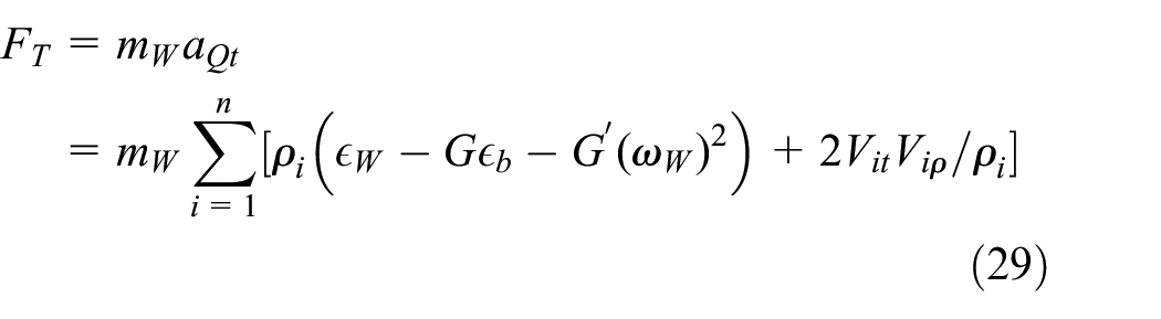
Where,
On the other hand, the friction resistance on the shaft is related to the friction coefficient


In the equation, the expressions of A and B are consistent with the above.
If

If the above equation is satisfied, the wheel can keep rotating continuously. In actual drilling process, the force Fc is usually small enough so that it can be ignored, besides, teeth are usually arranged as tightly as possible so that the teeth spacing is small enough. Actually, cemented carbide teeth is not the only option to be used on the wheel, in order to reduce the teeth spacing, steel teeth with smaller sizes or cemented carbide wheel with teeth integrated thereon can also be applied, so that the teeth can be disposed more tightly and the teeth spacing can be smaller. With smaller teeth spacing, when the teeth contact the rock alternatively, the impact vibration caused by subsequent teeth is smaller, and the scratch continuity caused by the teeth is better.
Conclusion
(1) A new type of vertical-wheel hybrid PDC bit is proposed in this paper. The vertical wheel rotates along its vertical axis when the bit drills in bottom-hole, which is beneficial to the drilling performance of the bit. Firstly, it is an auxiliary cutting structure sharing rock-breaking work for fixed wing-blades. Secondly, the rotation of the wheel changes part of the sliding friction of the bit into rolling friction, so as to reduce the torsion and stabilize the torsion fluctuation on the bit. Thirdly, the wheel itself is a buffer for protecting the bit from impact load. Fourthly, the wear rate of the teeth can be reduced by penetrating the rock alternatively.
(2) To study the rock-breaking behavior of the vertical-wheel hybrid PDC bit, a coordinate system for the vertical wheel is established, on basis of which the equations of speed and acceleration of the vertical wheel are derived. Specifically, the average rotation speed of the wheel is:

According to the speed equation, the wheel/bit speed ratio is furtherly derived, which is:

(3) According to the experiment, the average speed of the wheel is most sensitive to the changes of the wheel diameter and the normal deviation angle. Specifically, the fitted average speed is inversely proportional to the quadratic of diameter and varies with the normal deviation angle in a sinusoidal function:
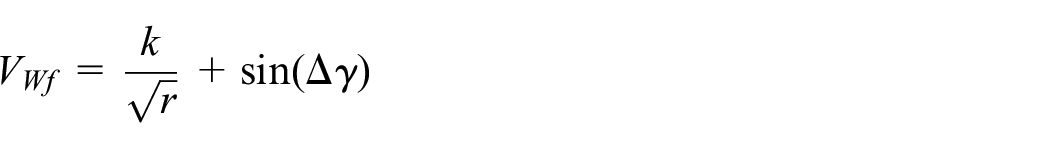
And analysis on the instantaneous rotation speed shows that the speed changes as a sinusoidal function with respect of time, which is:

Accordingly, the calculated average speed of the Ø18 mm vertical-wheel according to the instantaneous speed model is 4.532 r/s, while the average speed obtained in experiment is 4.491 r/s, with an error of 0.9%, proving that the measuring method and modeling of the instantaneous speed are credible.
(4) If the wheel shall rotate continuously, the driving force

Besides, the teeth spacing should be less than the maximum value, which is:
Footnotes
Handling Editor: Chenhui Liang
Declaration of conflicting interests
The author(s) declared no potential conflicts of interest with respect to the research, authorship, and/or publication of this article.
Funding
The author(s) disclosed receipt of the following financial support for the research, authorship, and/or publication of this article: This research has been supported by the City school cooperation project of Nanchong science and Technology Bureau (Project No. SXQHJH021).