
Abstract
The present work contributes to the research on the damping properties of fibre composites through an experimental approach by using the free damped vibration measurement based on impulse-force system response, the developed measurement stand and laser Doppler vibrometry. Moreover, the influence of the material configuration on the damping properties was investigated and was compared with conventional homogeneous isotropic materials. The measurement was based on the analysis of flexural vibrations generated by the Dirac impulse force, as well as on the free decaying-vibrations response; the time- and frequency-domain modal identification was employed. The fibre composites were represented as layered bidirectional long carbon- and glass-fibre composites (laminates) with different material configurations and as short carbon-fibre composites.
Keywords
Introduction
Manufacturing companies are forced to innovate and improve quality to gain a competitive advantage and differentiation in the market; this can be achieved by introducing new and modern materials. Composite materials are an alternative to traditional materials. Moreover, one of the most important steps in product design, which consists of technical and industrial design, is the material selection in the pre-production stages. According to Gutteridge and Waterman, 1 the purpose of the material selection process is described as the identification of materials which, after appropriate manufacturing operations, will have the dimensions, shape and properties necessary for the product or component to demonstrate its required function at the lowest cost.
According to Mazumdar, 2 the material selection process involves the four following steps: understanding and determining the requirements, the selection of possible materials, the determination of candidate materials and the testing and evaluation. For example, the requirement of weight reduction of machines and engines, as well as the demand for increase in productivity, can be the significant source of the greater vibrations and noise emission.3,4 Therefore, appropriate material selection is of paramount importance, particularly given the variety of new and advanced materials that exist at present.
At the beginning of the composites era, most research works and analyses in the field of composite materials were focused on the estimation of static properties through analytical, numerical, experimental and hybrid approaches. Researchers have been making efforts in the effective numerical simulation and the suitable estimation of the mechanical properties, such as Young’s modulus of elasticity, the shear modulus and Poisson’s ratio, of anisotropic materials for different shapes and reinforcement arrangements. Extensive literature is available on this topic.5–8 It was found that even the damping properties of composites are strongly affected by the volume fraction of the reinforcement.9–13 Moreover, in general, the sources of energy dissipation are the internal hysteresis, interface or joint friction and external or air damping. In Paimushin et al., 14 it is stated that the aerodynamic damping increases significantly with vibration frequency and dimensions of test samples. A summary of the current state of methods and models of composite damping properties can be found in Zhou et al. 9 Nevertheless, a deeper understanding of the dynamic properties and inner microstructural effects is important for the effective use of composites in industrial applications.
Research on damping and vibration characteristics with respect to the effect of fibre orientations in different lay-up was conducted in Bozkurt et al., 15 Abramovich et al. 16 and Nagasankar et al. 17 It was observed that damping and vibration characteristics of the composite samples were strongly affected by the fibre orientation of the basalt/epoxy composite. The increase in the angle of the fibre orientation from 0° to 45° resulted in a decrease in the natural frequencies and an increase in the damping ratios. 15 It was found that the loss factor, η, obtained via the hysteresis loop method was linearly dependent only on the applied excitation frequency and was independent of the preloading and the stress amplitudes. 16 In Bulut et al., 18 the results revealed that the position and the percentage of the fibres in composites were the most effective parameters for natural-frequency and damping characteristics. Even in cutting, the amount of wooden reinforcement in wood–plastic composites affects the shape of the formed chips. 19 In Treviso et al., 20 it was stated that although not widely exploited yet, fibre-reinforced polymers have the potential to be tailored for damping by acting on constituents, geometry, and boundary conditions.
In recent years, investigations have been focused on improving (i.e. increasing the damping ratio without affecting the natural frequencies and reducing the amplitude of the vibration, among others) the damping properties of composites by incorporating polycaprolactone nanofibres into glass-fibre composites, 21 using SiC and fly ash as fillers with different weight fractions, 22 changing the temperature conditions through visco-elastic interlayers, 23 silica nanoparticles, rubber particles, 24 and so on. In Kern et al., 25 the viscoelastic properties of the carbon fibres in unidirectional carbon fibre/epoxy composites were predicted and were then optimised through the application of a thin glossy coating.
The typical measuring method for modal testing is the bump (impact) test by means of a special hammer with an attached force transducer. Modal testing is a method in which the data are fed as input to modal-analysis software to obtain the impulse response function (IRF), the natural frequencies, the damping ratios, the natural modes, the bandwidth and so on of the tested structure. The experimental determination of the resonant frequencies is based, for example, on the determination of peaks at frequencies in the amplitude spectrum. The shapes that correspond to their natural frequencies (resonance frequencies) would be determined by the imaginary spectrum of the frequency response function. 26
In general, the tested structure (i.e. the system and the sample) would be constrained with the desired boundary conditions. The constraints may be free – through the use of elastic cords (exhibiting the rigid-body behaviour at zero frequency) – very soft or fixed. The system responses under free boundary conditions created via the use of bungee cords are not sensitive to the bungee length, stiffness and position. 27 Naturally, models with different boundary conditions have different modal properties. Thus, it is essential that the boundary conditions be the same during the experiment and that the different sets of constraints be analysed individually.
In this article, the designed and manufactured measurement stand will be introduced, which was intended for the material selection and the appropriate development of the material configuration. In addition, we will present the obtained results and we will analyse the decay of the free-flexural vibrations for layered long-fibre composites (laminates) made of glass and carbon fibres with different material configurations (ply layout). The input requirements of the measurement stand will be provided in the corresponding section of the present work. Moreover, the experimental results will be analysed using the time- and frequency-domain evaluation method and will be compared with those of conventional materials, that is, mainly steel and aluminium alloys.
Materials and measuring methods
Materials
The samples which were used were either flat or cylindrical.
Flat samples (long-fibre bidirectional composites and conventional materials)
The measurement was performed on six square laminate, low-carbon steel- and aluminium-alloy samples with dimensions of 115 × 115 × 0.9 mm. Each laminate sample was composed of three layers of carbon- or glass-fibre twill fabrics in the matrix (Table 1, first column). Each layer was formed using bidirectional (2D woven) fabric. The carbon- and glass-fibre laminate samples were numbered as ‘1’, ‘2’, ‘3’ and ‘4’, ‘5’, ‘6’, respectively. The orientation of the individual layers was different (Table 1) in order to analyse the influence of each orientation. The orientation was determined by the orientation of the weft; the horizontal orientation corresponded to 0° (Table 1, black lines in the schema). The schemas of the layered lay-up and real carbon- and glass-fibre laminate samples are listed in Table 1. The carbon fabric was a twill weave (200 g/m2, twill 2/2) and a glass fabric (280 g/m2, twill 2/2). The three layers of fabrics are in matrix that is a mixture of epoxy resin (EpikoteTM Resin MGS® LR 285) and fixative (EpikureTM Couring Agent MGS® LH286) of a mutual ratio of 5:2.
Sample laminate lay-up description.

#: parallel to the edges of the sample; X: diagonal fibre orientation (45°).
Cylindrical samples (short-fibre composite and homogeneous materials)
The shape of the tested samples is cylindrical with centric holes (pipes) with an outer diameter of D = 12 mm, an inner diameter of d = 8 mm and a length of L = 110 mm. The cylindrical samples are shown in Figure 1 and will be briefly described in the following paragraphs.
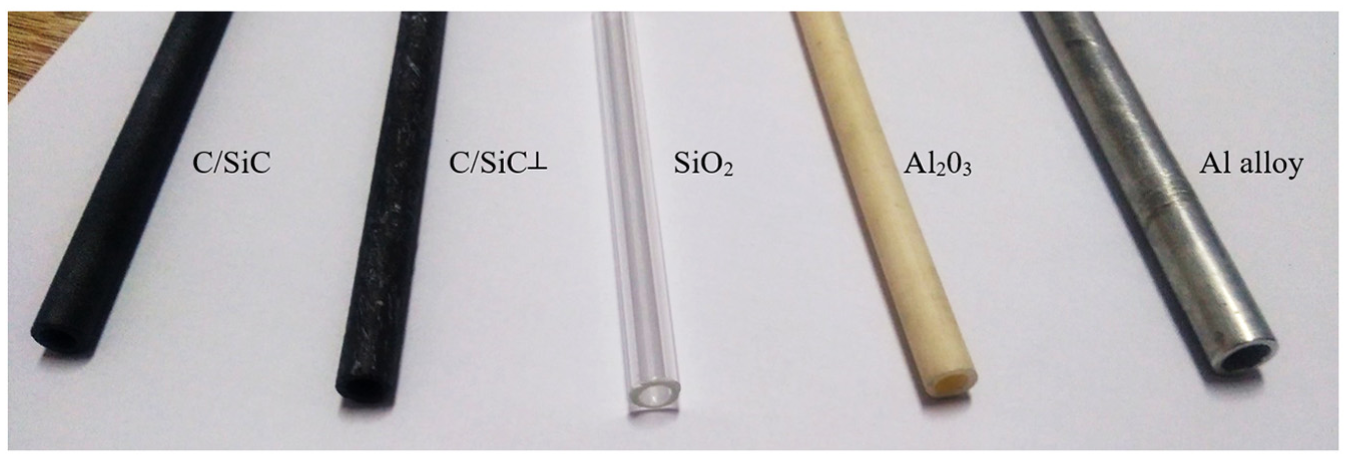
Cylindrical samples.
The steel and aluminium alloy (duralumin) represented conventional homogeneous isotropic materials of significant ductility (depending on the temperature). Both alloys had a crystalline lattice (cubic) when in solid form. The material density and the Young’s modulus of steel were approximately 2.8 times and 2.5 times higher, respectively. Technical glass and corundum would be unconventional for use in standard mechanical engineering applications; however, they are homogeneous isotropic materials.
Glass (SiO2) is representative of amorphous (i.e. non-crystalline), solid and brittle materials in a meta-stable state. The properties of such materials include a mass density of 2600 kg/m3, a Young’s modulus of 50–90 GPa and a minimum tensile strength of 33 MPa.
Corundum (sintered corundum ceramics with a minimum Al2O3 volume of 99.7%) is an oxide ceramic with a single oxide microstructure in crystalline form. Its material properties include a mass density of 4000 kg/m3, a Young’s modulus of 380–400 GPa and a minimum bending strength of 300 MPa.
Two samples were made of ceramic composites; they were C/SiC composites, meaning that they consisted of a ceramic silicon carbide–carborundum (SiC) matrix and short microscopic carbon fibres. Technically, SiC belongs to the non-oxide ceramics category. In production technology, silicon carbide is reinforced with carbon fibres, which mainly improves the mechanical and thermal properties of the original SiC. The C/SiC samples comprised short carbon-fibre rovings of a 3 to 6 mm length and a thickness size of 12K (1K corresponds to 1000 filaments). The C/SiC and C/SiC┴ samples had different fibre orientation in volume. The carbon fibres were randomly distributed in the C/SiC sample. In the C/SiC┴ sample, the short fibres had an orientation perpendicular to the sample axis. Some of C/SiC material properties were the following: the mass density was 2650 kg/m3, Young’s modulus was 250–350 GPa and the minimum bending strength was 160–200 MPa.
For the calculations of the mechanics of the material, the materials were assumed to be isotropic. This assumption could be applied to steel, aluminium alloys, glass, corundum, even for the C/SiC ceramic composite because the short fibres are randomly distributed; therefore, the C/SiC material had the same property values in all directions. The material properties of the C/SiC┴ sample can be recognised as orthotropic.
The measurement stand
The measurement stand was designed to avoid the use of the commercial bump hammer to determine the modal properties of the material, including its damping. Moreover, our samples were preferably of small size (up to 200 mm in width and height) and low weight (composites). In addition, the mass of accelerometer itself should not influence the results. In Smith et al., 27 it was stated that the use of accelerometers, even when accelerometers are a small fraction of the mass of the system (0.02% in the cited work), can significantly affect the measurements of damping and stiffness. Furthermore, to be able to repeat the measurement without the use of a bump hammer, the force value needed to be controlled without the use of sensors.
To develop a model of the stand (Figure 2, left), Autodesk Inventor Professional 2016 was used. The measurement stand was made of carbon steel E295. The base 1 (Figures 2 and 3(a)) had a thickness of 12 mm. In the middle of the base 1, the groove for the screw allowed to accommodate the large range of the position of the carriage 2. The lateral supports were welded to the base 1; hence, they did not interfere with the carriage 2. At the opposite end of the base 1, the clamp is fixed by four screws. The carriage 2 (Figures 2 and 3(b)) allowed the distance between the table and the measured sample to be changed. The carriage 2 was a welded structure consisting of plates of different thicknesses. The carriage 2 had two grooves (the grooves were perpendicular to one another); one groove was located at the lower side of the table and the other was located at the upper side. The carriage 2 was mounted to the base 1 via the lower groove to prevent the mutual movement of the carriage 2 and the base 1. The semi-circular cut-outs at carriage 2 allowed easier access to the screws. Moreover, the lateral sides were welded to the carriage 2 to allow the mounting of the displaceable transversal plate 3 (Figures 2 and 3(c)). The screw in the groove allowed the fixing of the plate 3 in the required position. The special nuts were welded to this transversal plate 3 to fix the threaded bars 4. These bars 4 were locked using contra-nuts to avoid spontaneous unlocking. The threaded bars 4 were used for the precise adjustment of the inclined impact ball runner 7 by means of other special holders 6 using adjusting screws that were movable along threaded bars 4. The outlet of the impact balls 5 (Figure 2) designed to avoid a secondary excitation by a potential repeated impact. The shape and dimensions of the outlet are proposed regardless of the shape and dimensions of the impact body. Naturally, its position should be adjusted in order not to touch the sample or the clamp 9.

3D model (left) and measurement stand with a flat sample.
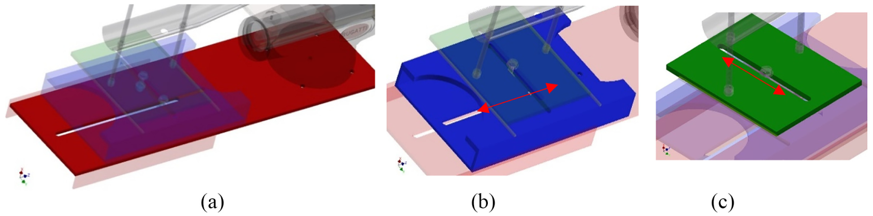
Details of the (a) base, (b) the carriage and (c) the transversal plate; arrows indicate the directions of possible displacement.
The impact ball runner 7 (Figures 2 and 4) was mounted in the special holders 6 using a pair of nuts on each side. The L-shape profile of the runner minimises the contact surface of the impact ball and the runner. In addition, the shape of the runner allows the use of various types and dimensions of impact bodies. The runner was 1-m long. Thus, the various lengths of ball-impact trajectories together with various ball-impact weights and materials allow a wide range of impulse-force values. The clamp 9 was equipped with flat and prism jaws; therefore, it allowed the testing of either flat samples or cylindrical ones up to 125 (maximum jaw expansion) × 500 × 500 mm. Moreover, the clamp 9 could be rotated up to 360° around the axis perpendicular to the base. Thus, the shape variability of the tested sample, the measurement stand, the position of the impact point and the impulse force were large. Furthermore, the clamp 9 could be dismounted and prepared for testing using free boundary conditions.
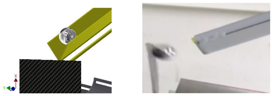
Impact ball: model (left) and experiment (right).
The measurement set-up description
The scheme (Figure 5, left) shows the elements of the measurement set-up. The main advantage of Polytec IVS 400 (Figure 5, right) is that it provides contactless and wear-free measurement that eliminates the influence of environmental conditions regardless of servo-mechanisms or noise protection to collect measurements. The vibrometer was based on a phenomenon of the Doppler shift in a laser beam to measure, for example, the vibration velocity, the amplitude of a moving object and so on. The light beam was reflected by the moving surface; thus, the frequency of light was shifted proportionally to its velocity. Laser Doppler vibrometry is significant in terms of the independence of the measured data on the reflected light intensity. Hence, the laser vibrometer is suitable for surfaces of low reflectivity.

Measurement set-up (left) and the Polytec IVS 400 on a tripod during measurements.
Certain technical data are the following: the operating temperature was 5°C–40°C, the velocity ranges were ± 20, 100 and 500 ms−1, the frequency range was 0–22 kHz (digital output) and the weight was 2.6 kg. Additional details can be found in the following URL: www.polytec.com.
If a wave is reflected by a moving object and detected by a measurement system, the measured frequency shift, fD (Doppler frequency), of the wave can be described as

where v is the velocity of measured object and λ is the wavelength of the emitted wave (of the laser light beam). To be able to determine the velocity of an object, the (Doppler-) frequency shift should be measured at a known wavelength. This measurement was obtained using a laser interferometer. The optical interference requires two coherent light beams – the light intensities of which were I1 and I2– to overlap. The resulting intensity was not merely the sum of the single intensities; it was modulated according to the following formula 28

with an ‘interference’ term. This interference term refers to the path length difference between the two beams;

Thus,

Then, the size of vector

Boundary conditions
The two constraint sets were used. The flat samples were fixed at one side (Figure 6, left), and the cylindrical samples were free of constraints (Figure 6, right).
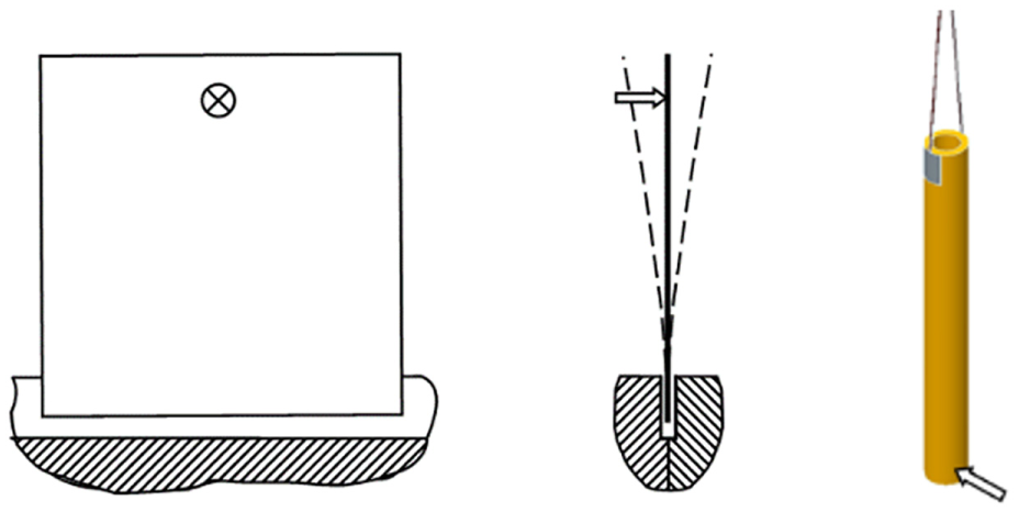
Boundary conditions – fixed (left) and free constraints, and point of impulse force action.
In general, the excitation options were the excitation either by falling (impacting) mass or by unfastening from the deformed position in order to obtain the Dirac impulse (unit impulse, delta function). The impulse response of the system would be the system output signal as a response to the unit impulse used as the input. 29 The samples were excited using the impulsive type of the excitation function generated by the impact ball.
The impulse force was applied in the perpendicular direction for flat samples to initiate free-flexural vibrations. In case of cylindrical samples, two impacts were applied in two radial directions perpendicular to one another. The applied impact can be considered as a low-velocity impact within the range of 1.5–2.5 m/s.
The value of the impulse force in the measurements was estimated according to a theoretical method in which assumptions based on Newton’s elementary theory of impact are used (according to Záhorec and Caban 30 ). The impulse force is a type of force acting on a body for a very short period. According to Murčinková et al., 31 the formula for the calculation of the magnitude of the impulse force, Fimp, at the end of the first period of the impact involving the translational and rotational motion of the impacting body is

where
The damped free vibrations were quasi-periodic because the amplitude of the previous cycle was not the same as the subsequent one. The logarithmic decrement, δ, was estimated in the time-domain modal identification, for example, the exponential decaying response (Figure 7) of the free vibrations excited by the impulse force. The logarithmic decrement was calculated over a number of cycles (n)

where
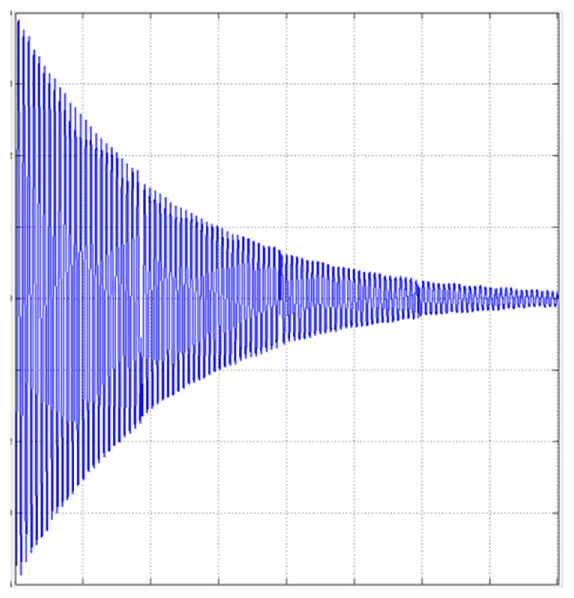
Decaying exponential response (time vs amplitude).
Results and discussion
Laminate-layered composite reinforced by bidirectional long fibres
The graph in Figure 8 depicts the evaluation of the measured first two natural frequencies of the samples based on the fast Fourier transformation (FFT) analysis of the measured vibration velocity values. Samples ‘1’ (‘4’), ‘2’ (‘5’) and ‘3’ (‘6’) were of the same carbon (glass)-fibre twill type, the same matrix material and had the same number of layers and dimensions. The only difference was in the material configuration. In this case, the difference in the material configuration pertained to the different orientations of the laminate layers and, thus, the different orientation of the material properties. The values of the impulse forces were 332 N, 680 N, 2917 N and 5978 N, which were calculated using formula (6). The applied values of the impact forces did not have an important influence in the evaluation of the natural frequencies of individual samples. The differences changed within a very small range. This was caused by both the material configuration and the measuring error. We can state that the material configuration did not have a significant influence on the natural frequency. The first natural frequency was higher in the case of the carbon-fibre laminate for all impulse forces (F1–F4); however, the second natural frequency was greater for the glass-fibre laminate (Figure 7). Furthermore, the fibre orientation increasing from 0° (Samples 1 (4)) to 45° (Samples 2 (5)) caused a decrease in the first natural frequency.
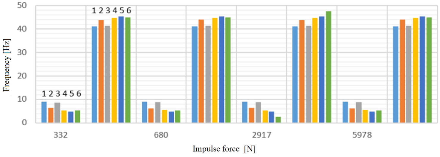
Natural frequencies.
The logarithmic decrement estimated according to equation (7) differs in relation to the material and the material orientation, Figures 9 and 10. Figure 9 provides time decaying curves for the listed materials and configurations (the initial mess caused by bump is not shown; the first shown cycle is a cycle of maximum amplitude). The larger the logarithmic decrement is, the less the number of cycles required to reduce the amplitude, Figure 9 (e.g. CXXX and IGXXX: logarithmic decrement 0.0358; 0.0441 and 67; 59 cycles to reduce the amplitude 10% of maximum, respectively). As the stiffness of the carbon fibre is greater, the logarithmic decrement is lower compared with the glass-fibre laminates. The ability of carbon-fibre laminates to absorb the vibration energy is lower than that of the glass-fibre laminate. However, in the case of carbon-fibre laminates, the logarithmic decrement may be lower (up to about 33% for lay-ups ### and #X#) or higher (up to 49% for lay-up XXX) compared with conventional material, for example, steel, and depends on the material configuration, Figure 10. The strong advantages of carbon-fibre composites are their high stiffness and high specific modulus of elasticity, among others. It may be noticed that the material configuration influences the damping properties. We would be able to tailor the material configuration for specific boundary conditions and depending on the damping. In the case of lay-up #X#, the different middle layer does not influence the logarithmic decrement significantly; it merely causes it to slightly decrease compared with lay-up ###. Furthermore, the fibre orientation increasing from 0° (Samples ‘1’ (‘4’)) to 45° (Samples ‘2’ (‘5’)) cause an increase in the logarithmic decrement.

Time decaying curves.

Logarithmic decrement.
Composites reinforced by short fibres
Figure 11 summarises the results of the measurements of the cylindrical samples. The materials on the horizontal axis are arranged in the same order as that illustrated in Figure 1. The specific modulus of elasticity was calculated as Young’s modulus of elasticity, E, by the mass density, ρ. The composites reinforced with short fibres had a high natural frequency, short damping time and a large specific modulus of elasticity. Involving the three aforementioned evaluated properties, the short-fibre composites presented the best damping properties. Although the C/SiC material had third natural frequency, it has the shortest damping time and the highest specific modulus of elasticity. Young’s modulus of elasticity of the C/SiC┴ material with fibres which were perpendicular to the axis is not available. The natural frequency and damping time of C/SiC┴ were very similar to those of C/SiC, that is, 6690 Hz and 6.6 ms, respectively.

Natural frequency, specific modulus of elasticity and damping time.
The damping time was evaluated as the time at which the maximum amplitude decreased to 10% of its value. It may be observed that the damping time was very short in the case of composite-material samples. Such materials are highly appropriate for the design of components intended for dynamic loads with variable exciting frequencies. The Al2O3 sample has a longer damping time by several times compared with other samples. If the non-damped Al2O3 sample (or component) would be excited by dynamic force, the vibrations amplitudes would be greater.
Moreover, the hatching of the natural frequency columns in Figure 11 corresponds with the shape of the FFT frequency spectrum. Figure 12 shows a typical shape of the narrow and wide frequency zones of the dynamic response. The narrow FFT spectrum is characterised by individual sharp resonance peaks comparing with the multiple peaks of the wide FFT spectrum without the dominant natural frequency. The property of the wide frequency zone range causes the desired decreased- and weak-resonance phenomenon. Comparing the FFT spectrums of both composites (Figure 12(a) and (c)), the difference is visible. The short-fibre composites provide the appropriate dynamic response because of their high-energy dissipation capability.

Typical FFT spectrums (natural frequency/magnitude) of the layered long-fibre laminate (a), steel (b), short-fibre composite (c) and aluminium alloy (d).
Discussion
After evaluating and observing the results, we may draw the following general summary regarding the study of the damping properties based on flexural vibrations that were generated by the impulse force and the free-vibration decaying response of various types of the aforementioned fibre composites:
The material configuration influenced the logarithmic decrement as the selected representative for the characterisation of the damping properties.
The natural frequency was slightly affected by the material configuration.
Fibre reinforcement is beneficial to dynamic performance, as observed after comparisons with the dynamic performance of homogeneous isotropic materials.
The measurement results confirm that the macroscale dynamic properties, mainly material damping, of fibre composites can be modified through the inner microscale structure. Moreover, based on results, we confirm that the material configuration of fibre composites affects the damping properties, for example, the increase in the angle of the fibre orientation from 0° to 45° resulted in a decrease in the first natural frequency and an increase in the damping properties. Furthermore, we confirm the potential of fibre composites to be tailored and controlled for damping through the microscale material configuration.
We assume the excellent damping properties of short fibres composites lie in the relatively large surface of the interfaces between the short fibres and the matrix. Although short fibres are stiff, their effects on the fibre–matrix interface are the source of fine damping and energy dissipation. In the case of layered long-fibre composite materials, we assume that the layer–layer interface could improve their damping properties.
Conclusion
In this work, we experimentally analysed the influence of the material configuration on the damping properties by means of a developed measurement stand and by employing the corresponding methods for the estimation of the damping quantities (time- and frequency-domain identification). The developed and presented measurement stand was intended for material process selection and for the development of the appropriate material configuration of advanced materials. We conducted modal testing (without mode-shape identification) on composite materials to compare the damping properties of different configurations of composite laminates.
The benefits and novelty in field of measurement and mechanics of materials are the following:
The experiment set-up involves a developed modifiable measurement stand with contactless vibrometer and vertically situated sample to eliminate the non-uniform gravity influence; moreover, it is a new equipment of the department laboratory and contributes to material testing and selection. No special impulse bumper was required; thus, hammer self-resonances were avoided. The stand provides various options for boundary conditions existed for the tested bodies (components and samples): fixed and free constraints and positions of the bump point. The impulse force can vary by changing the length of the trajectory; the weight and the material of the impacting body influenced the time of impact. The gravity affected the results evenly because the samples were clamped in the vertical position and the sample deflection was in the horizontal direction. The measuring was contactless and without the use of an accelerometer, the weight of which would substantially affect the results; the weight of the samples was low (several tens of grams). Various shapes and sizes of the tested bodies can be investigated, namely flat samples (components) up to approximately 500 mm (either height or width) and cylindrical shapes up to a diameter of 125 mm. Almost rigid construction with the ability to adjust the various positions were required for measurement purposes.
Short-fibre composites present superiority in their dynamic response in terms of their very short damping time, large logarithmic decrement, and wide FFT spectrum compared with layered long-fibre bidirectional composites. We documented various FFT spectra for different types of composite materials and thus we confirm suitability of their usage for dynamically loaded components, for example, in machine tools. We provide comparison mainly of damping properties of isotropic conventional materials and long and short fibre composite in one work. The potentiality of composites to be tailored and controlled for damping through the microscale material configuration is serious for research.
Footnotes
Acknowledgements
The authors would like to thank the Agency of Ministry of Education, Science, Research and Sport of the Slovak Republic for supporting this research (Grant VEGA 1/0910/17).
Handling Editor: Liyuan Sheng
Declaration of conflicting interests
The author(s) declared no potential conflicts of interest with respect to the research, authorship, and/or publication of this article.
Funding
The author(s) disclosed receipt of the following financial support for the research, authorship, and/or publication of this article: the Agency of Ministry of Education, Science, Research and Sport of the Slovak Republic for supporting this research (Grant VEGA 1/0910/17).