
Abstract
The most performant system for heating in electric and hybrid vehicles is the heat pump. This study proposes a heating system with a reversible heat pump, which works as a conventional air conditioning system in cooling mode and in heating mode it uses a secondary circuit with water/glycol to transfer the heat from the condenser to the heater core located in the air conditioning module. This system was experimentally validated with 61 tests in heating mode and 19 tests in cooling mode. In the heating mode, there is a test which was developed with an ambient temperature of -1ºC with the air circulating through the outdoor unit at a velocity of 3.2 m·s−1, an air flow rate of 388 kg·h−1 supplied to the cabin and the compressor running at 2866 r/min. At these conditions, the air is supplied to the cabin at 41.5ºC, the heating power is 4.2 kW and the COP is 1.9. In the cooling mode, there are tests developed at a condenser supply air temperature of 45.4ºC with a velocity of 5.7 m·s−1. The air is supplied to the vehicle cabin with a temperature of 14.6ºC with a flow rate of 508 kg·h−1, with a cooling capacity of 3.88 kW and a coefficient of performance of 1.8.
Introduction
Heating in automotive applications is mandatory due to security concerns, because it allows to avoid fogging on the glasses and to improve the driver concentration in cold environments. In conventional vehicles, there is enough waste heat to heat the vehicle cabin through the engine cooling system, but in the case of electric vehicles, the heating is a little more complicated because this heat source is not already available due to the highest efficiency of the electric motor. Moreover, the waste heat of the electric motor is at a lower temperature than the waste heat of the combustion engine, thus this heat has a lower quality. In electric vehicles, there is another heat source in the batteries’ cooling system, which is also at a lower temperature compared to combustion engine and with a lower heating capacity compared to the cabin heating demand. Some researches propose to reduce the peaks of energy demand by using a thermal storage system. The energy consumption of the heating/cooling system can also be reduced by improving the insulation of the vehicle and by using more efficient glazed surfaces.
By considering that the available heating sources in the electric vehicles are not enough to satisfy the cabin heating demand, new heating systems and new heating architectures must be investigated and proposed. In the literature, the heating systems that are normally considered for electric vehicles are as follows: systems based on a vapour compression system and alternatives systems, such as electric resistances, positive temperature coefficient (PTC) heater and combustion heating systems.
Vapour compression systems are the most investigated ones for heating in electric vehicles, due to the reliability and to the technological maturity of this kind of technology in automotive applications. In this case, there are several possibilities to implement it, for example, to use an air source heat pump or to use a double source heat pump (ambient air and waste heat). Another alternative to consider is the reversibility of the heat pump, to use it for heating and cooling, which requires a specific architecture.
Suzuki and Ishii 1 presented a reversible air-to-air heat pump working with R134a which allows cooling, heating and dehumidifying. It was tested at two ambient conditions of 40ºC and -10ºC, by obtaining a cooling and heating demand of 3.1 and 5.4 kW, respectively, with coefficients of performance (COPs) of 2.9 and 2.3. In this study, an electric compressor was considered. Pommé 2 presented an improved architecture for a reversible heat pump, which includes two evaporators: one taking heat from the ambient air and another one taking heat from some equipment such as batteries, electric motor and control system. The author used an electric compressor with refrigerant R134a. With this system, the author obtained a system COP of 1.74 at an ambient temperature of -10ºC. Scherer et al. 3 developed a study of a heat pump working with R134a and R152a, but this system uses the engine coolant as heating source, which is not a realistic working condition of an electric vehicle. According to the experimental results, both refrigerants give similar results, satisfying widely the cabin heating requirements up to -10ºC. Jokar et al. 4 developed an experimental study on a reversible heat pump working with two-secondary loops with glycol/water on the outdoor and on the indoor units and using R134a as refrigerant. This is maybe a less attractive solution from the efficiency point of view due to the losses introduced by the secondary loops. Ahn et al. 5 presented an experimental study developed on a dual source heat pump working with R134a and with an electric twin rotary compressor. The testing campaign is developed for a single (air and water) and dual source. According to the results, with a single source, the system is not able to satisfy the cabin heating demand at -10ºC. With a dual source, the authors do not explain clearly in the article if the system satisfies the cabin requirements, but the authors conclude that the heating power depends strongly on the waste heat recovered from equipment. Feng and Hrnjak 6 developed an experimental study of a reversible air-to-air heat pump, which is part of two commercial electric vehicles. The heat pump was tested in laboratory with refrigerant R134a and in cooling mode it is able to regulate the air humidity giving the possibility to cool and to heat the air supplied to the vehicle cabin. At an ambient temperature of 0ºC, this system is able to supply 3.1 kW of heating at an outdoor air face velocity of 3 m·s−1 without air recirculation to the cabin, by giving a COP of the order of 2.7. Wang et al. 7 present an experimental study of a reversible air-to-air heat pump working with an electric scroll compressor, which can work at variable speed. This system was tested with two refrigerants: R134a and R407C. According to the experimental results, the proposed system is able to satisfy the cabin heating demand down to -10ºC.
In the past few years, the research on electric vehicles heat pumps have focused on the compressor, by analysing mainly vapour-injected compressors, on dehumidifying systems and defrosting strategies. Some of the latest researches are summarized below.
The vapour injection in compressor is mainly used to reduce the compressor exhaust temperature and to increase the heat pump heating power. Most of the studies evaluating vapour-injected compressors are developed using scroll compressors and evaluate the effect of the shape and position of the injection porthole.8–12
With respect to the defrosting process, in an experimental study, Steiner and Rieberer 13 analyse the reverse cycle defrosting process in a reversible air-to-air heat pump for vehicle application using R744 as refrigerant. According to the experimental results, the defrosting process takes less than 2 min. In a second study, Steiner and Rieberer 14 analyse the ideal defrost start time, which according to their results is between 15 and 20 min. Zhou et al. 15 also used the reverse cycle method for defrosting in a reversible air-to-air heat pump, with the heat pump working at -20ºC. According to their experimental results, the time for defrosting can be controlled within 100 s. In heating mode, after the condenser, the refrigerant flow is separated into two heat exchangers, one located outside, used as evaporator, and other one used as an economizer to inject cold vapour into the compressor to decrease the high temperature at the compressor discharge.
Other studies have been developed to evaluate the dehumidifying performance of the heat pumps to reduce the effect of fogging in the cabin and to reduce the fresh air incoming into the cabin, which decreases the vehicle energy demand. In this sense, Ahn et al. 16 experimentally evaluated a dual source evaporator in an air-to-air heat pump for vehicle application. In this case, one evaporator is located outside and the other one upstream of the condenser to dehumidify the air. Zhang et al. 17 evaluated an antifogging system based on the air recirculation and on an antifogging air curtain in an air-to-air heat pump. The highest COP obtained with this system was 1.56 for a recirculation ratio of 0.56. Another numerical study, developed by Zhang et al., 18 proposes to use a desiccant-coated heat exchanger. According to their results, the cabin heat load and the compressor electric power are decreased by 42% and 38%, respectively, at an ambient air temperature of -20°C.
According to the previous researches, most of the studies are developed by using R134a as refrigerant and an electric compressor. Due to the high Global Warming Potential (GWP) of the refrigerant R134a, it only gives a baseline for the future refrigerants that will be used in automotive applications. On the other hand, electric compressors seem to be the best choice to reduce the transmission losses. Concerning the sources, the use of an air source heat pump presents some constraints at low temperatures due to the frosting and the lower efficiency of the heat pump. It seems that a temperature of -10ºC is the lowest temperature that gives reasonable COPs, without any auxiliary heating system.
In particular, in this study, a heating system based on a reversible heat pump is proposed. In cooling mode, the proposed system works as a conventional cooling system and in heating mode, it uses a water/glycol cooled condenser to heat the vehicle cabin through a conventional heater core. The system evaluated here is originally proposed for a hybrid vehicle, by offering the possibility to have a heating source coming from the combustion engine or a heating source supplied by the heat pump. In this case, a mechanical compressor is considered, in order to maintain the system as close as possible to a conventional automotive air conditioning (AC) system, and the refrigerant is R134a. The aim of this study is to validate through an experimental characterization the architecture proposed in this study in both heating and cooling modes, by identifying some performance characteristics such as cooling and heating power and COPs and to evaluate the system performance under frosting.
Heat pump working principle
A heat pump is a thermal machine used to transfer thermal energy from a source to a sink. It uses a vapour compression cycle which is implemented using a compressor, a condenser, an expansion valve and an evaporator. Each component is connected with the others through hermetic pipes and filled with a fluid called commonly refrigerant. The refrigerant is circulated by the compressor, by consuming external energy, mechanical or electrical. Thus, the refrigerant is circulated through the evaporator, where it takes heat from the source, by releasing it in the condenser to the sink. Thus, the heat pump is a machine that ‘pumps’ heat from a source to a sink. The useful energy of this machine could be the heat taken from the source, in the case of the refrigeration machine, or the heat released to the sink, in the case of the heat pump. When a heat pump can work in both modes heating and cooling, it is called reversible heat pump.
The working principle of the reversible heat pump investigated in this study is shown in Figure 1, which was already presented by Lemort et al. 19 In cooling mode, the heat pump works as a classical automotive AC system, and in heating mode, it works as an air to glycol–water heat pump, by transferring the heat flow to the automotive cabin through a heater core located in the AC module.

Reversible heat pump working principle.
In heating mode, the uniqueness of this system is that it can be used in hybrid vehicles by changing the heating source between the combustion engine and the heat pump through the secondary glycol water circuit.
The heat pump is assembled using conventional AC automotive components. The compressor is a variable swept volume wobble plate compressor; the front heat exchanger (outdoor heat exchanger) is a conventional louvred fin and plate heat exchanger, used normally as condenser in automotive AC systems; and the heater core (indoor unit in heating mode) and the evaporator (indoor unit in cooling mode) are the heat exchangers located inside a conventional automotive AC module. To complete the system, a conventional expansion valve and an aluminium plate heat exchanger are selected for the heating circuit.
The front heat exchanger works as a condenser in cooling mode and as an evaporator in heating mode, the plate heat exchanger is only used in heating mode as condenser. The AC module is decomposed in an evaporator, a heater core, a thermostatic expansion valve and a fan used to circulate the air into the vehicle cabin. The main advantage of this configuration is that the conventional vehicle AC system is slightly modified, by replacing the heating source given by the internal combustion engine by the plate heat exchanger. One disadvantage of this system is that in cooling mode there is no possibility to reheat the air supplied to the cabin to better control its relative humidity. To change from heating to cooling mode, a conventional 4-way valve is used. Figure 2(a) and (b) show the system with their corresponding components.

Components of the reversible heat pump: (a) cooling mode and (b) heating mode.
The refrigerant selected for this application is R134a and for the heating circuit, a mixture of ethylene glycol with water 50/50 by mass.
Test bench description
General description
The schematic principle of the test bench used to characterize the heat pump is shown in Figure 3. This is used to validate the proposed configuration and to characterize experimentally the heat pump to determine its performance under different working conditions in both heating and cooling modes.

Schematic of the refrigerant circuit.
The test bench can be decomposed in four circuits: a closed air circuit representing the ambient air, an open air circuit representing the air supplied to the vehicle cabin, a glycol/water circuit and a refrigerant circuit. Each circuit is instrumented with pressure, temperature, humidity, mass, and volume flow sensors to determine the energy flows through each component.
Outside air circuit
The ambient air is here represented by a semi-closed loop, which is conditioned to match the ambient conditions in heating and in cooling modes. In heating mode, it is coupled to an external refrigeration system that is used to supply cool air down to -15ºC. The humidity in this circuit is not controlled, but in order to avoid frosting in the evaporator, the closed air loop is connected to a compressed air circuit, which provide dry air. This configuration allows carrying out tests in steady state conditions without frosting formation on the evaporator.
In cooling mode, the heat rejected by the condenser is transferred to three cooling coils installed in the air loop, which are also used to control the air temperature. The air velocity is adjusted by modifying the damper opening located at the fan exhaust.
Cabin air circuit
In heating mode, the cabin air circuit is coupled to the outside air circuit in order to have almost the same conditions at the AC module supply than the conditions at the evaporator supply, which corresponds to a case without air recirculation from the vehicle cabin. The same configuration is adopted in heating mode, by coupling both air circuits to have the same air conditions at the AC module supply and at the condenser supply, which corresponds to a condition without air recirculation from the vehicle cabin. In a first measuring campaign, the air flow rate was measured with a hot wire anemometer and in a second campaign with an orifice plate with a diameter of 77.7 mm inserted in a 106 mm tube diameter. In this circuit, the humidity is not controlled, but it is measured at the inlet and outlet of the AC module to perform a good energy balance in cooling mode.
Glycol water circuit
The glycol/water circuit is used to connect the condenser to the AC module when the heat pump is working in heating mode. This circuit is equipped with a volume flow meter to determine the glycol/water mass flow rate. In cooling mode, this circuit is not used.
Refrigerant circuit
The refrigerant circuit interconnects the different components of the heat pump. In this circuit, a Coriolis mass flow meter is used to measure the refrigerant mass flow rate. The main components of this circuit are described below: compressor, outdoor heat exchanger, AC module and four-way valve.
Compressor
The compressor is a variable displacement wobble plate compressor with seven pistons and a swept volume of 161.3 cm3. This compressor is charged by the manufacturer with 135 cm3 of polyalkylene glycol oil. Despite the fact that the compressor has a variable displacement, during the entire measuring campaign, the compressor was tested at its maximum displacement while working at variable speeds.
The compressor is installed inside a calorimeter to determine its ambient loss by using the same principle described by Cuevas et al. 20 A set of three thermocouples are installed on the compressor crankcase to determine a weighted average surface temperature, which is then used to determine the compressor ambient loss coefficient.
The compressor shaft power is measured by installing it in a pivoting system, similar to the system described by Cuevas et al. 20 The compressor torque is then measured by a load cell, which is used with the compressor speed measurement to determine its shaft power.
Outdoor heat exchanger
The outdoor heat exchanger is a louvered fin and flat tubes heat exchanger. It is located in the front part of the vehicle and it works as evaporator in heating mode and as condenser in cooling mode.
On the air side, nine thermocouples are installed upstream and downstream the heat exchanger to determine its energy flow, as shown in Figure 4. The air flow rate is measured with two nozzles of 190 mm and two nozzles of 80 mm, which are combined to give a reasonable pressure drop.

Outdoor heat exchanger.
Glycol/water heat exchanger
The glycol/water heat exchanger, shown in Figure 5, is an aluminium brazed plate heat exchanger having the dimensions of 175 mm × 100 mm × 75 mm (high × width × depth).

Plate heat exchanger.
This heat exchanger only works in heating mode. The heating fluid is here a mixture of ethylene glycol and water in a proportion of 50/50 by mass, and it is circulated in the test bench by a circulator pump.
AC module
The AC module is a typical car AC module composed of a fan, a heater core, an evaporator and its thermostatic expansion valve, which are integrated inside the module as shown in Figure 6.

AC module.
The expansion valve is a block type thermostatic valve, which has neither external thermostat nor external pressure equalizer. The heater core is here connected to the glycol/water heat exchanger, which works only in heating mode.
Four-way valve
A four-way valve is used to change from heating to cooling mode. This valve was slightly oversized to reduce the circuit pressure losses.
Measuring devices
Compressor calorimeter
The compressor is installed inside a calorimeter to determine its ambient loss. To control the calorimeter ambient temperature, it is equipped with a fan-coil and a lamp. The ambient temperature is controlled by modulating manually the water flow rate circulating through the fan-coil. Figure 7 shows a view of the calorimeter indicating its main components.

Compressor calorimeter.
To determine its ambient loss, the calorimeter was calibrated by introducing known internal loads and by performing its steady-state energy balance. The calorimeter conductance identified in this study is equal to 3.58 W·K−1
Torquemeter system
As explained in Cuevas et al., 20 the compressor is installed on one extremity of an out-of-use electric motor used to transmit the compressor shaft torque. The compressor power is then determined by measuring the resultant force produced by the torque arm system and the compressor rotational speed. Due to the parasitic torque introduced by the pipes connected to the compressor, this system must be calibrated beforehand to perform each testing campaign. The resistant torque is determined by the following equation

where α and β are constants determined from calibration, xs = 0.152 m is the torque arm, Fs is the applied force on the torque arm and Fs0 is the parasitic force introduced by the compressor connections.
Finally, the compressor shaft power is determined as

ωcp is the compressor angular speed.
Measuring devices
Table 1 summarizes the uncertainty of the different sensors used during the experimental characterization of the system.
Uncertainty of the sensors used in the test bench.
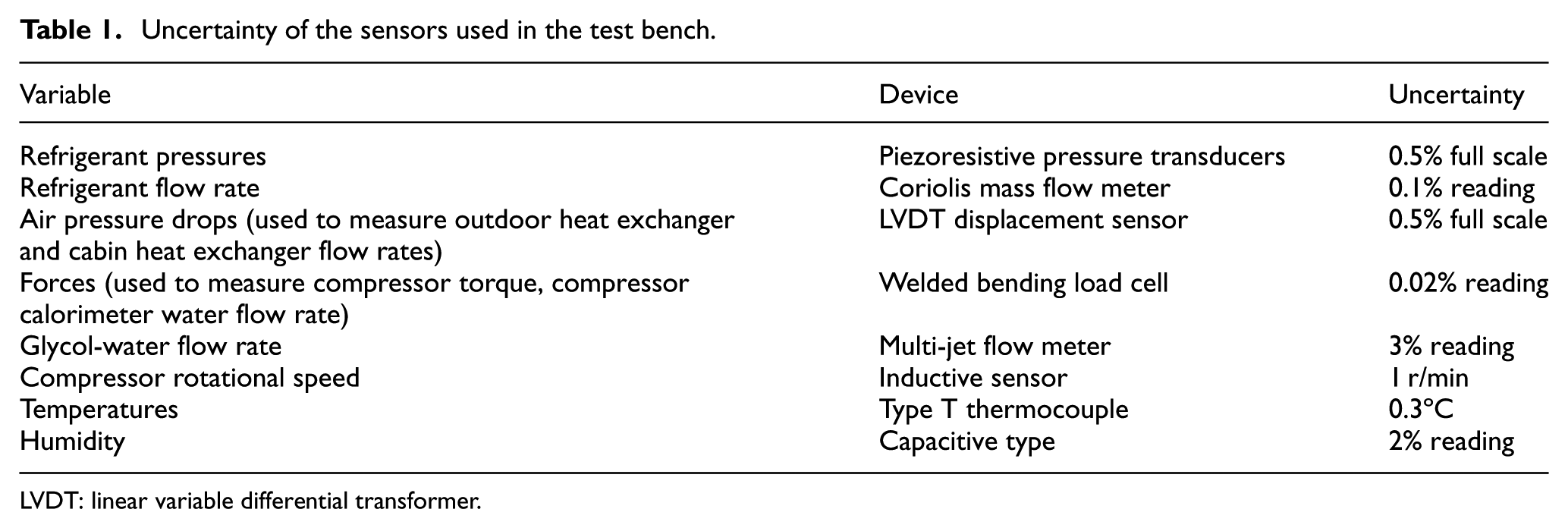
LVDT: linear variable differential transformer.
Several testing campaigns were developed to determine the database presented in this study. In the last testing campaign, several improvements were made to the test bench in the measuring chain.
Test pre-processing
The tests are developed in steady-state conditions. The data acquisition system is programmed to develop one acquisition per second. Once the steady-state is reached, the system is maintained in those conditions at least for 30 min. Then, for the pre-processing, a period of 30 min in steady-state is taken to determine the average values that are then used to perform the energy balances on each component and on the overall system.
Experimental results
The heat pump was characterized in steady state with 61 tests in heating mode and 19 tests in cooling mode.
Compressor isentropic and volumetric effectivenesses
According to the experience of the authors, the first variables to be determined in this kind of systems are the isentropic and volumetric effectivenesses, which are here shown in Figures 8 and 9 against the compressor pressure ratio and classified according to the compressor speed. Both effectivenesses are determined with the following equations
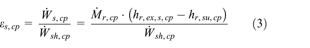

Where

Compressor isentropic effectiveness against compressor pressure ratio.
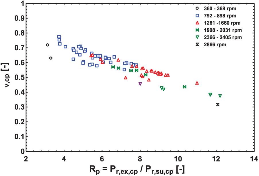
Compressor volumetric effectiveness against compressor pressure ratio.
For the isentropic effectiveness, a typical decreasing trend with the pressure ratio is observed. The results have a high scattering and by comparing them to previous results, obtained by Cuevas et al., 20 no correlation with the compressor speed is observed. Thus, according to these results, the pressure drop through the compressor valves are negligible and do not penalize enormously the isentropic effectiveness in the range of compressor speeds covered in this study. The high scattering observed here is mainly attributed to the way used to measure the compressor torque.
For the volumetric effectiveness, the typical decreasing trend with the pressure ratio due to the re-expansion of the clearance volume is also observed. Here, the scattering is lower, but no correlation with the compressor speed is observed again, which confirms the conclusion derived from the isentropic effectiveness concerning the low effect of the compressor valves pressure drop on the compressor performance.
Calorimetric energy balance of the compressor
The calorimetric energy balance of the compressor is used to determine the compressor ambient loss, which can be used in the modelling of this component. According to the results, shown in Figure 10, the compressor ambient loss coefficient is 4.4 W·K−1.

Compressor ambient loss.
Heating mode
In the following analysis, and by considering that the compressor used here is a mechanical compressor, a global efficiency of 90% will be considered to convert the compressor shaft power to an equivalent electric power to obtain more realistic results.
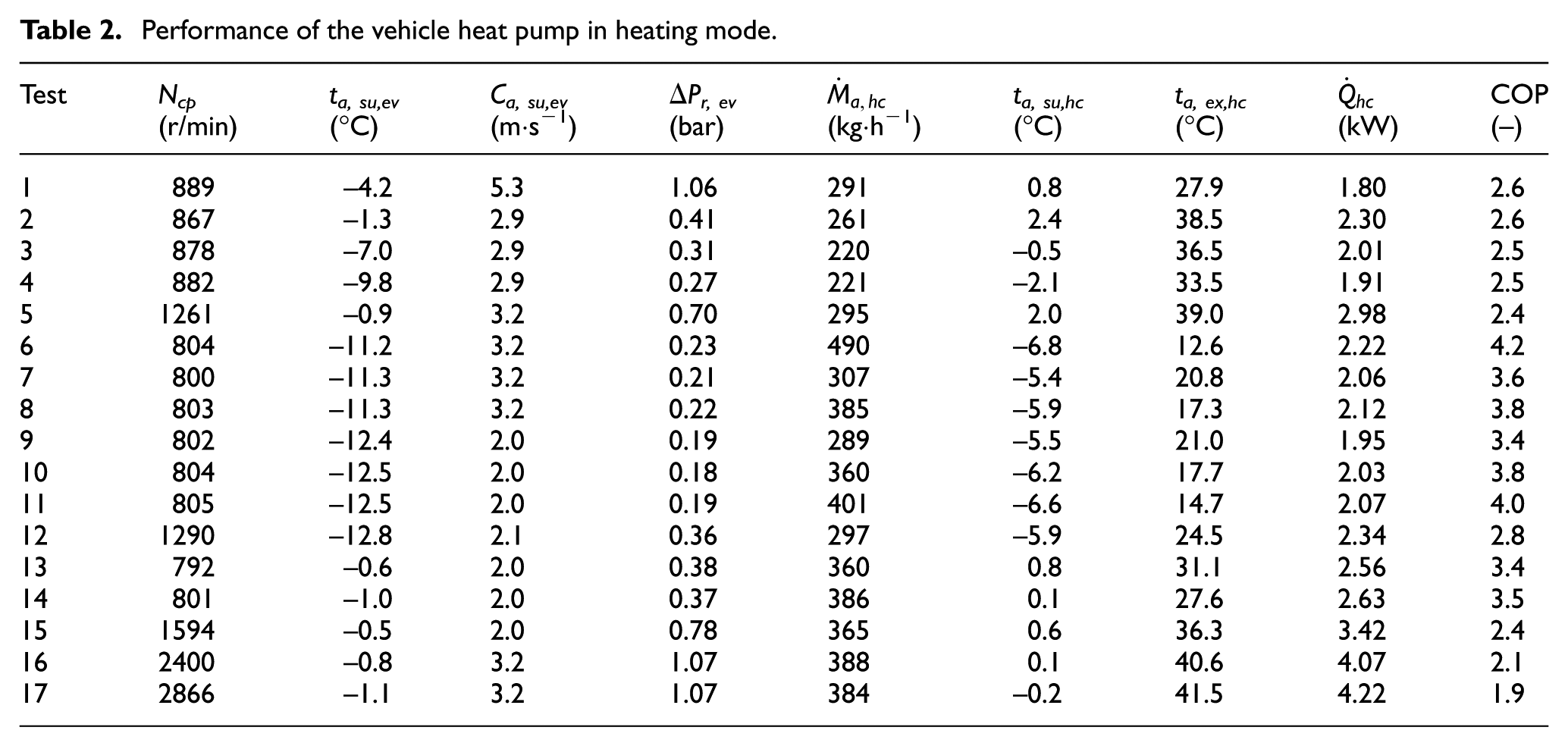
Table 2 shows 17 of the 61 tests developed for the heat pump in heating mode. This table only considers the results for low air temperatures at the evaporator supply (ta,su,ev). Due to the configuration of the test bench, it was difficult to fix the same air temperature at the evaporator (ta,su,ev) and heater core (ta,su,hc) supply due to the ambient parasitic heat transfer, but the conditions obtained are similar to the conditions with cabin air recirculation. According to the results, the heater core power, the cabin supply temperature (ta,ex,hc) and the heat pump COP are very sensitive to the compressor speed. Tests 16 and 17 are more representative of a realistic working condition, with a cabin supply temperature close to 45ºC (design condition) by giving a reasonable COP of 1.9 to 2.1, with a heating power of the order of 4.1 kW at -1ºC ambient temperature, a cabin supply temperature of the order of 41ºC and a compressor speed of 2400–2860 r/min. According to the results, the evaporator presents too large pressure drops on the refrigerant side. These pressure drops are close to 1 bar at high capacity, which can be reduced by improving the design of this component.
Performance of the vehicle heat pump in heating mode.
Cooling mode
Table 3 presents 14 of the 19 tests developed in cooling mode. Only the testing conditions with condenser air supply temperature higher than 35ºC are considered in this table. In this case, it was also complicated to regulate independently the condenser and the evaporator supply conditions, because both are connected to the same air stream. As in heating mode, the heat pump performance is very sensitive to the compressor speed. In order to evaluate the experimental results, the test 10 is considered, which is developed at a condenser supply temperature (ta,su,cd) of 45.4ºC, a condenser air velocity (Ca,su,cd) of 5.7 m·s−1, an evaporator air supply temperature of 40.8ºC and an evaporator air mass flow rate of 508 kg·h−1. At these conditions, the air is supplied to the vehicle cabin at 14.6ºC and the evaporator cooling capacity is of the order of 3.88 kW, by giving a COP of 1.8.
Performance of the vehicle heat pump in cooling mode.

Frosting–defrosting cycling
Two cycles of frosting and defrosting are considered to evaluate two defrosting strategies. The test is developed at an average ambient temperature of -4ºC, an average ambient relative humidity of 84%, an average air velocity at the outdoor unit inlet of 2.4 m/s and an average compressor speed of 1630 r/min.
The two defrosting strategies analysed in this study are the following:
Strategy 1: Defrosting by reversing the heat pump cycle,
Strategy 2: Defrosting by turning off the compressor.
These two strategies are shown through the air side pressure drop at the outdoor unit in Figure 11. In this figure, the frosting is observed when the pressure drop through the outdoor unit increases up to the point when defrosting cycle starts.

Air side pressure drop during the frosting-defrosting cycling.
The performance of every strategy is evaluated through the compressor energy consumption, heating energy and system COP for every phase and globally. The three phases considered are phase 1: frosting; phase 2: defrosting; and phase 3: starting heating mode. In both cases, the system COP is higher than 2.1. In this case, the heating energy is equal to zero during phase 2, because the glycol water circulator is turned off.
Table 4 summarizes the results of the defrosting strategies analysed in this study. In this case, the COP is determined as
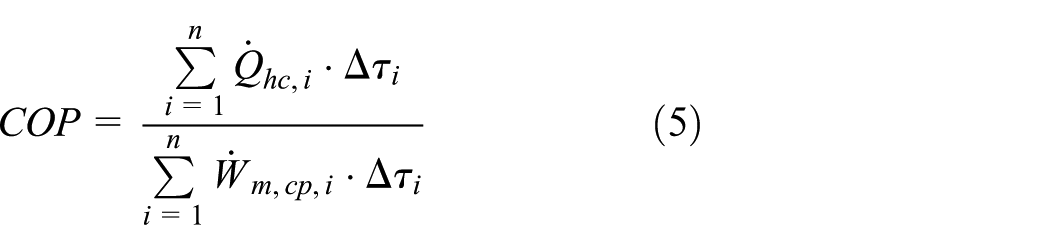
where
Performance of the defrosting strategies.

COP: coefficient of performance.
In this case, the defrosting time for the reverse cycle defrosting strategy was 447 s (7.45 min).
Analysis of the results and discussion
According to the results presented in Table 2, at an ambient air temperature of -1ºC, the system analysed in this study presents a COP of the order of 1.9 to 2.1. This result is obtained without air recirculation from the vehicle cabin, with a heating power of the order of 4.1 kW and with air supplied at 41ºC to the vehicle cabin. This result is not easily comparable to the other research studies due to the operating conditions are not always similar. The system COP depends on the air temperature, compressor speed, heating capacity and cabin supplied temperature. In spite of that, the results obtained in this study seems to be very promising considering the improvements that can still be introduced to the system evaluated here. Some improvements are discussed below.
The system proposed in this study presents several alternatives of improvements, which could be analysed in further researches. In spite of that, the system evaluated here does not present any technical problem by allowing to work at ambient conditions down to -10ºC.
Concerning the improvements of the system there are several recommendations. In this study, a mechanical compressor was used, which is more recommendable for conventional vehicles with combustion engines or in the case of hybrid vehicles, but in the case of purely electric vehicles is more recommendable to use an electric scroll compressor, which allow to reduce the transmission loss and to profit of the comparative advantages of the scroll compressor compared to the piston compressor.
Another improvement is related to the outdoor heat exchanger. In this study, an automotive condenser was used as outdoor heat exchanger. In condenser mode, the refrigerant is supplied on the top of the heat exchanger and in evaporator mode on the bottom. The circulation in this heat exchanger is optimized to work as condenser, with the refrigerant circulating in four steps. In the first step, there are more channels for the refrigerant, to reduce the pressure drops, by maintaining a good heat transfer coefficient. In the last step, where the refrigerant is in liquid phase, there are less channels due to the lower pressure drop of the liquid and to maintain good heat transfer coefficients. When this heat exchanger is used as evaporator, the pressure drops increase up to 1 bar. This can be improved by designing an outdoor heat exchanger more optimized to work in both heating and cooling modes.
As mentioned previously, the system tested in this study is more recommendable for hybrid vehicles, since it uses a mechanical compressor and the heating source in heating mode can be easily changed between the heat pump and the combustion engine. This configuration can be improved in the case of purely electric vehicles, by suppressing the secondary circuit and by using an air cooled condenser installed directly in the airstream supplied to the vehicle cabin. In this case, some manufacturer16–18 recommends to use two evaporators, one installed in front of the vehicle and other one installed upstream the condenser to dehumidify the ambient air. This improvement allows to reduce the fogging and the heat pump energy consumption.
Finally, the refrigerant must be changed due to high value of the GWP of the R134a. Thus, a refrigerant with a GWP lower than 150 should be considered for this application and evaluated numerically and/or experimentally.
Conclusion
This study presents a reversible heat pump principle for automotive application, which was assembled and characterized experimentally for validation in both modes: heating and cooling. During the testing campaign, the components and the system do not present any technical constraint.
In heating mode, the system was validated with 61 tests and in cooling mode with 19 tests. These tests allowed to determine the compressor characteristics, such as its ambient loss with an overall heat transfer coefficient of 4.4 W·K−1 and its isentropic and volumetric effectivenesses. The isentropic effectiveness presents a high scattering, which is attributed to the random uncertainty in the compressor shaft power measurement. Any dependence of the effectivenesses on the compressor speed as in previous studies was not observed, thus apparently the compressor valves do not significantly penalize the compressor performance.
In heating mode, the heat pump was characterized by using dry air at the outdoor unit in order to avoid moisture condensation and frosting, and to develop more stabilized tests. In this mode, the design cabin supply temperature was 45ºC, but in the tests, it was closer to 41.5ºC for an ambient temperature of -1ºC, by giving a heating power of 4.2 kW and a COP of 1.9, which is considered as an acceptable value.
In cooling mode, the design ambient temperature is 45ºC. For the analysis, a test with a condenser supply air temperature of 45.4ºC with a velocity of 5.7 m·s−1 is considered. In this case, the air is supplied to the vehicle cabin with a temperature of 14.6ºC with a flow rate of 508 kg·h−1, by giving a cooling capacity of 3.88 kW and a COP of 1.8.
In general, the heating system proposed in this study was validated technically by using a heat pump for electric and hybrid vehicles, and in terms of performance, it showed an acceptable efficiency, which can still be improved by changing some components, such as the compressor, which can be replaced by an electric scroll compressor, and improving the outdoor unit which can be adapted to be efficient in both heating and cooling modes with acceptable pressure losses.
The system was also characterized to evaluate the frosting–defrosting cycling through two strategies. The best COP is obtained by turning off the compressor, but the frequency of frosting is higher in this case, because the outdoor unit is partially defrosted. Reversing the cycle seems to be a good alternative for the defrosting phase with an acceptable COP and defrosting time.
Footnotes
Appendix 1
Handling Editor: James Baldwin
Declaration of conflicting interests
The author(s) declared no potential conflicts of interest with respect to the research, authorship, and/or publication of this article.
Funding
The author(s) received no financial support for the research, authorship, and/or publication of this article.