
Abstract
The actual power capacity of permanent magnet synchronous machine for electric vehicles is usually limited by rotor temperature, and rotor overheating is one of the major reasons for permanent magnet synchronous machine failure. Therefore, an approach of rotor temperature estimation is proposed to improve motor peak power utilization and protect permanent magnet synchronous machine from serious demagnetization due to thermal damage. A real-time iterative algorithm is provided based on the equivalent thermal model for rotor temperature. First, the heat generating principle of each part as well as the power flow transferring of the motor system is analyzed. Second, rotor temperature model is built based on the conservation of energy loss from the stator and real-time superposition of temperature variation rate for the rotor. Finally, the motor performance test bench is built to validate the proposed algorithm and numerical models are also constructed to simplify estimation parameters for rotor temperature model. The algorithm accuracy is improved and verified by optimizing control parameters with given environment temperature and power load. The experimental result shows that the maximum error between actual test value and estimation value is within ±10°C, and it meets the requirement of algorithm accuracy and also benefits on system performance and manufacture cost efficiently.
Introduction
Permanent magnet synchronous motor (PMSM) plays an important role in electric vehicle industry due to its advantages including high power density, high operation efficiency, as well as excellent start torque, and the present researches focus on how to improve motor thermal safety and excellent torque capability with smaller size. Copper, eddy-current, and hysteresis losses are responsible for an abundant temperature rise in magnets, and temperature is the core limiting factor for how long PMSM can continuously be loaded. The development of rotor temperature model (RTM) is not only a safety issue but also a performance issue. On one hand, the magnet intrinsic coercivity is a function of temperature performance and its absolute value decreases with the increase in temperature. When the rotor temperature exceeds limiting value, irreversible demagnetization occurs in magnets.1–3 In general, PMSM design should ensure that no irreversible demagnetization occurs in expected operation condition. On the other hand, PMSM torque usage expectation is lower than its fact capability without high accurate rotor temperature estimation (RTE) to avoid its overheating and thermal damage.4–6 In addition, PMSM dimension can be avoided to cut down the cost of magnetic material usage if real-time RTE is available to assure continuous safe operation mode for motor.
Usually, measuring the temperature of the rotor permanent magnet is very difficult by equipping sensors to rotate the body directly. Some common techniques include slip rings, infrared sensors, and wireless temperature device. Compared with direct measuring of temperature by embedding temperature measuring devices into motor integration, implementing real-time thermal model in motor controller is a cost-effective and rapid response protection method, but real-time RTE currently still faces some challenges on thermal model complexity, algorithm operation safety, as well as temperature estimation accuracy. According to this research, there are three main categories to estimate rotor temperature of the motor. The first method is the traditional experience formula which indirectly measures some parameters correlated with RTE to obtain the expected value of rotor temperature.7–9 The second method is the finite element analysis which builds thermal resistance between each unit and forms thermal network to verify estimation results by inputting compensation units into thermal network model.10–12 The final method is to measure counter electromotive force and calculate remaining field density used to look up the table with actual rotor temperature for PMSM.13–15 Based on previous arguments, there are still several disadvantage factors to estimate rotor temperature under actual operation state for PMSM. First, there is ignorance of rotor temperature variation after vehicle system powers off, especially in the condition of natural cooling, so there is no way to obtain the initial value of rotor temperature when vehicle system powers on again. Second, there is just consideration for the magnet temperature properties with the normal environment to bring the low level of robustness and estimation accuracy at the present, so it is necessary to optimize the algorithm by combining important factors such as environment temperature. Finally, it cannot be applied to unload the driving current during the actual motor operation when we adopt counter electromotive force to obtain the rotor temperature indirectly.
Although RTE has been studied, there are still other problems such as large parameter dependence, complicated measuring, and computation. In order to solve these problems, an iterative algorithm is provided based on the equivalent thermal model to estimate real-time rotor temperature and it is necessary to equate and simplify thermal model with fewer control parameters and computation. Hence, an applicable and advanced RTM is proposed to predict the real-time thermal performance of PMSM. First, the power loss of each part is analyzed and the power flow transferring of PMSM is described. At the same time, RTMs with fewer control parameters are constructed precisely based on conservation of energy loss from the stator. Second, the control strategy is introduced based on different operation states and numerical models which are provided to support RTM algorithm. Finally, the performance test bench for PMSM is built and a series of experiments are carried out on the hardware and software of PMSM controller to verify whether the RTM estimation accuracy meets the requirement with different environment temperature and variation power load.
Thermal analysis based on PMSM power loss
In order to attain actual rotor temperature precisely, the essential reason for heat generation should be deeply explored and the principle of energy flow transfer among motor thermal nodes is described in Figure 1. Based on motor operation state, important factors of thermal effect are analyzed and power loss models of thermal nodes are built. There are four parts of power loss such as copper power loss, iron power loss, mechanical power loss, and cooling power loss, respectively.16–18

Energy flow analysis for main parts.
Copper loss analysis
Copper loss power

where
where
Iron loss analysis
Iron loss power

where
Mechanical loss analysis
Mechanical loss

where
Cooling loss analysis
Cooling loss consists of two parts: one is absorbed by cooling water in the cooling circuit and the other is consumed by the stator and the rotor to the atmosphere. Therefore, cooling loss for water can be concluded by the following empirical equation24,25

where
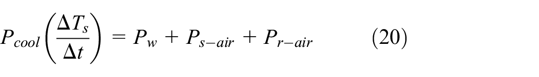
In addition, cooling power which comes from the stator and the rotor to the atmosphere can be expressed by the following empirical equations26,27


where

where
Equivalent estimation for RTM
The effect of RTE is greatly influenced by factors of operation states and environment temperature. Therefore, actual RTM which is embedded into PMSM controller should be simplified to the equivalent estimation model based on theory and experiment method.
RTM for motor operation state
According to the power flow analysis of main thermal nodes from Figure 1, it is concluded that heating power of the stator

The power dissipation of the stator
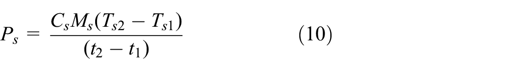

where
Meanwhile, the stator will liberate heat energy to the atmosphere using cooling water and the rotor acts as a heating energy resource. Therefore, the absorbing heat power of the rotor can be concluded based on the conservation of energy as

Combining equations (5)–(12), real-time rotor temperature

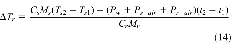
here, the value of
RTM for motor stationary state
When motor comes to the stationary state, the rotor, acting as a heating energy resource, liberates heat energy to the atmosphere and its temperature goes down to the environment temperature with stationary time. Therefore, temperature variation regulation of the natural cooling state should be explored. When vehicle is on, rotor initial temperature is attained by adopting the previous rotor temperature
Read values of
Receive value of environment temperature
According to stationary time
Finally, rotor initial temperature

where

Rotor temperature variation with stop time.
Rotor temperature control strategy
According to the previous RTM, a comprehensive control strategy is built to estimate the real-time rotor temperature which is fit for different environment temperatures and motor operation states. There are two main parts to be described in detail.
Control algorithm procedure
Algorithm process is developed based on previous RTM in Figure 3. First, power supply state and actual operation state of electric vehicle should be determined by signals of vehicle speed and gear position to meet requirement of real-time estimation on rotor temperature. Second, RTM is used to predict rotor temperature according to motor actual state. And then, rotor temperature should be modified in appropriate condition due to accumulation error generated by iterative algorithm. Finally, rotor temperature should be stored in EEPROM of motor controller when vehicle comes to power down


where
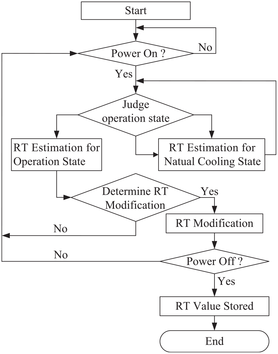
Flowchart of rotor temperature algorithm.
Software framework description
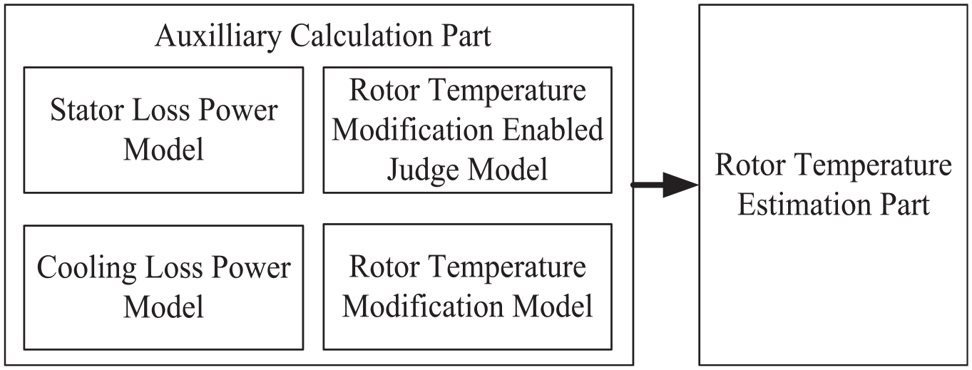
According to previous RTM and algorithm process of RTE, algorithm framework can be built to develop software details. There are five main parts from Figure 4 to describe their functionalities, respectively, as follows:
Stator loss power model is responsible for calculation of the stator loss power based on the stator temperature;
Cooling loss power model is responsible for calculation and calibration of cooling loss power based on the stator temperature changing rate from the stator loss power model;
Rotor temperature look-up table with enable model is responsible for judging whether to enable look-up table or not based on motor speed and motor torque;
Rotor temperature modification model is responsible for obtaining rotor temperature modification value based on three-phase vector volts, motor speed, as well as look-up table enabled flag;
RTE model is responsible for estimating and modifying rotor temperature based on support of previous four models.
Framework of rotor temperature estimation.
Numerical models for RTM estimation
To improve the actual application of RTM, correlative numerical models are built by experiment and embedded into algorithm framework of software. In addition, RTM should also be simplified to applicable and effective algorithm model for hardware support of motor controller.
Flux linkage model
Usually, there is accumulation error for RTE by iterative algorithm. Therefore, flux linkage model related with rotor temperature should be obtained to modify the estimation error of rotor temperature when it meets the requirement of modification condition from equations (16)–(18).
The numeric model of flux linkage can be built by actual experimental results in Figure 5. Furthermore, actual flux linkage can be calculated based on given motor speed, counter electromotive force, as well as pole pairs in equation (19)

where

Flux linkage related with rotor temperature.
Cooling numerical model for motor operation state
There are three main parts of cooling loss power including cooling water loss power
where

Total cooling power with different temperature variation rates for the stator.
Cooling numerical model for motor stationary state
It is necessary to attain rotor initial temperature

where

Rotor temperature variation with stationary time.
Experimental test for RTM algorithm
The performance test bench for PMSM is built to verify the estimation accuracy of RTM algorithm in Figure 8. For this test bench, it consists of electric dynamometer, battery simulator, adjustable low volts power, electric parameter tester, personal computer, CAN sample device, water cooling system, environment chamber, PMSM sample, as well as motor controller.

PMSM performance test bench.
Temperature sensors layout
Based on RTM algorithm proposed in this article, it is necessary to monitor the stator real-time temperature and calculate the stator temperature variation rate. Here, temperature sensors are attached to the surface of the stator winding with insulated and heat-resistant glue (from Figure 9). In addition, temperature sensor is attached to the surface of the rotor alnico with insulated and heat-resistant glue (from Figure 10) to verify rotor estimation accuracy compared with RTM algorithm.

Stator temperature sensor layout.

Rotor temperature sensor layout.
RTM algorithm accuracy verification
To verify RTM algorithm accuracy at different operation states, the proposed algorithm in this article is embedded into motor controller and a series of experiment schemes are worked out as below.
Result analysis for test 1
When it comes from operation state to stationary state, PMSM is in the state of natural cooling. According to the test results from Figure 11, RTE value decreases with stationary time because there is no operation power from PMSM and no heat radicalization from the rotor to the environment. The maximum error between the estimated value and the actual test value is within ±4°C during stationary condition.

Test results with environment temperature 30°C during stationary state: (a) estimated results compared with measured results during stationary time and (b) the error between the estimated and the measured results during stationary time.
Result analysis for test 2
When it comes into constant load power with the same environment temperature, PMSM is in the constant operation state. According to test results from Figures 12 and 13, RTE value increases with operation time because heating radialization power from the stator is greater than rotor dissipation power from cooling water and environment. The maximum error between the estimated value and the actual test value is within ±5°C during constant operation condition. In addition, estimation errors can be considered as feedback that is used to optimize total cooling power
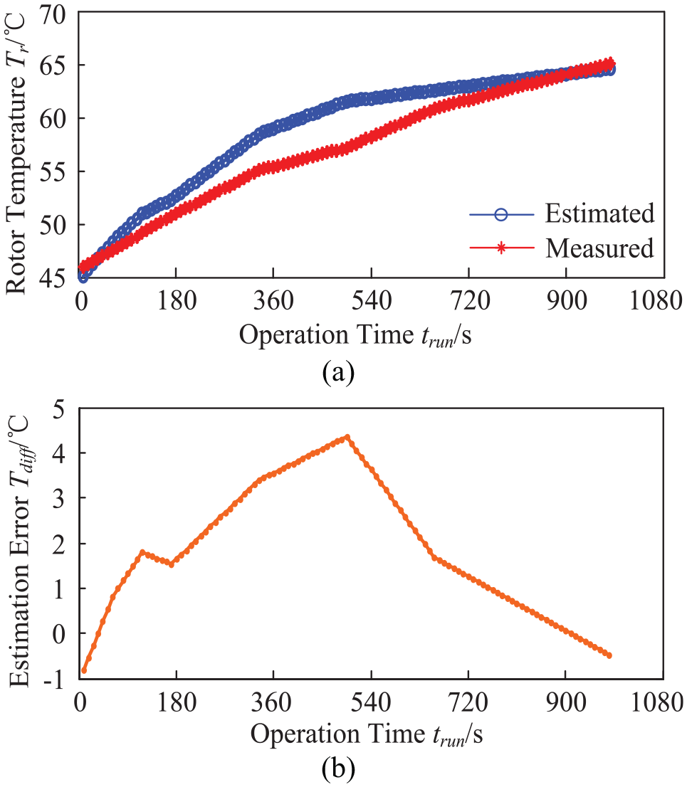
Test results with environment temperature 30°C during constant operation state (100 Nm with 3000 r/min): (a) estimated results compared with measured results and (b) the error between the estimated and the measured results.

Test results with environment temperature 30°C during constant operation state (130 Nm with 3000 r/min): (a) estimated results compared with measured results and (b) the error between the estimated and the measured results.
Result analysis for test 3
When it comes into the variational load power with different environment temperatures, PMSM is in the variational operation state. According to test results from Figures 14 and 15, when operation power comes from high level to low level, estimation value decreases with operation time because heating radicalization power from the stator is less than rotor dissipation power from cooling water and environment. Reversely, the estimated value goes up with operation time. Test results show excellent transient behavior at different environment temperatures, and the maximum error between the estimated value and the actual test value is within ±10°C during dynamic operation condition.

Test results with environment temperature 30°C during variational operation state: (a) variational operation power, (b) estimated results compared with measured results, and (c) estimated errors.

Test results with environment temperature 60°C during variational operation state: (a) variational operation power, (b) estimated results compared with measured results, and (c) estimated errors.
Conclusion
To protect PMSM from overheating, breakdown, and improve continuous behavior of motor torque, an applicable real-time algorithm of RTE is proposed in this article. Each part of heat generation and power flow transferring of PMSM is analyzed;
RTM is constructed based on real-time iterative algorithm of the equivalent thermal model and conservation of the stator energy loss under PMSM’s actual operation state. The proposed algorithm is embedded into motor controller by obtaining experiment datum to build correlative numerical models and simplify RTM;
The test bench of motor performance is built, and a series of experiment schemes are worked out to optimize and verify the real-time accuracy of the proposed algorithm in this article. Test results show that the estimated accuracy is within ±5°C and ±10°C during constant operation and variational operation conditions, respectively. Computation effectiveness of real-time rotor temperature algorithm can meet the requirement of high-accuracy estimation to improve continuous utilization of motor torque, power intensity, and cut down manufacturing cost with smart PMSM size in the next step.
Footnotes
Handling Editor: Xiaodong Sun
Declaration of conflicting interests
The author(s) declared no potential conflicts of interest with respect to the research, authorship, and/or publication of this article.
Funding
The author(s) disclosed receipt of the following financial support for the research, authorship, and/or publication of this article: This work was supported by the Changan Multicomponent Integration of Electric Drive System (Grant No. 67612-53010210-030128), National Natural Science Foundation of China (Grant No. 51305473), Chongqing Research Program of Basic Research and Frontier Technology (Grant No. cstc2016jcyjA0582), and Chongqing Postgraduate Research and Innovation Project (Grant No. CYS18225).