
Abstract
The wheeled capsule hydraulic transportation is a new technique for transporting materials. In this technique, the wheeled capsule, which is designed to contain materials, is one of the core components. In this study, a new type of wheeled capsule structure was first designed, and then experiments were conducted at seven water discharges, eight wheeled capsule dimensions, and eight mass of transporting materials in the pipe with an inner diameter of 100 mm. The pipe in study was divided into nine parts, and the speed of the wheeled capsule in each pipeline section was analyzed. The results showed that the speeds of the wheeled capsules in different sections of the pipeline did not change significantly and basically fluctuate near the overall average speed and the maximum relative fluctuation value was ⩽ 8.6%. Therefore, the overall average speed of the wheeled capsule can be used to analyze the motion characteristics of the wheeled capsule. The average speed of the wheeled capsule increased with increasing water discharge, diminished with increasing mass of transporting materials, increased with increasing length of the wheeled capsule, and increased with increasing diameter of the wheeled capsule. The empirical formula of the average speed of the wheeled capsule with different water discharges, wheeled capsule dimensions and mass of transporting materials was obtained by the nonlinear regression method and can be expressed as
Introduction
The wheeled capsule hydraulic transportation is an emerging technique for transporting materials through a pipeline. In this technique, a new wheeled capsule is first made into a cylindrical shape with six small cylindrical braces. Then raw materials are put into the wheeled capsule and sealed. Finally, the wheeled capsule is placed into the pipeline and is transported by the action of the flow. 1 The greatest feature of the transporting technique is not only its economical and practical value, but also energy-saving and environment-friendly characteristics. 2
The wheeled capsule hydraulic transportation was developed based on the coal log pipeline hydraulic transportation. Coal log pipeline hydraulic transportation 3 was proposed by Henry Liu at the University of Missouri-Columbia in the 1990s, resulting in a U.S. patent. In this technique, coal powder was first compacted into coal logs, followed by transporting the coal logs by pipe over great distances.4,5 Liu et al and others experimentally investigated hydrodynamics, the design of transportation pipelines, coal log manufacturing, wear of coal logs, and the effect of polymer additives.6–9 However, in coal log pipeline hydraulic transportation, coal powder needs to be molded or extruded into water-resistant and wear-resistant cylindrical coal log before being transported and coal log needs to be processed into coal powder after being transported, thus increasing the transportation cost. In addition, the transporting technique has a narrow range of materials and can only transport single solid powder materials. In addition, the movement of coal log in pipeline transportation is unstable. Its front and rear sections are bumping up and down, colliding the pipe and affecting the life of the pipe. Based on this, in 2007, Sun Xihuan at the Taiyuan University of Technology proposed a technique of wheeled capsule hydraulic transportation. 1 Following that Sun Xihuan et al., 1 Zhang Xuelan et al.,10–12 Jia Xiaomeng et al., 13 Jing Yuanhao et al., 14 Zhang Qiqi et al., 15 Sun Lei et al., 16 Zhang Chunjin et al., 17 and Li Yongye et al.,18,19 experimentally investigated the hydraulic characteristics in detail. These studies indicate that in the process of transporting materials in the wheeled capsule, the pressure distribution of the flow in the pipe decreased with increasing transporting distance. The pressure distribution of the wheeled capsule’s surface showed a decreasing trend, followed by an increase along its length. For the same cross-section, the flow pressure at the center of the pipe was small and the flow velocity was large, while the flow pressure and velocity distribution at the pipe wall were opposite to those at the pipe center. The front end face of the wheeled capsule had less impact on the flow than the rear end face. However, these studies do not provide sufficient information regarding the motion of the wheeled capsule. The motion characteristics of the wheeled capsule have not been addressed in order to industrialize the technique of wheeled capsule hydraulic transportation. Therefore, in this study, the motion characteristics of the wheeled capsule were investigated experimentally aiming to provide optimal wheeled capsule structural parameters.
In the wheeled capsule hydraulic transportation, the wheeled capsule is one of the core components. The appropriate structure design can directly determine the transportation consumption of energy and the transportation cost of this technique, further affecting its practicality and prospect for industrialization and application. Thus, the structural design of the wheeled capsule is very important. The wheeled capsule is mainly composed of barrel, brace, and universal ball. The shape of the barrel was designed as a hollow cylinder to expand the range of transporting materials. In order to load and unload materials more conveniently, both ends of the barrel and the circular seal covers were designed to be threaded sealing connection. According to the curvature radius of the bend pipe section designed in the test, the maximum length and diameter of the wheeled capsule were designed as 150 mm and 80 mm, respectively. Three cylindrical braces of 120° interval angle were designed and installed at both ends of the barrel to reduce the friction between the barrel and the inner wall of the pipe. The length and diameter of the cylindrical brace were designed as 25 mm and 7 mm, respectively. The braces make the barrel’s axis and the pipe’s axis always coincident and keep their movement concentric, overcoming the unstable motion defect of the barrel. Universal balls with a diameter of 3 mm were designed and installed separately at the end of each brace to further reduce the friction between the barrel and the pipe wall and increase the life of the pipeline. The structural sketch map of the wheeled capsule is shown in Figure 1.

Structural sketch map of the wheeled capsule: (a) Schematic diagram. (b) Physical diagram.
Experimental procedure
Experimental system
The experimental system of the wheeled capsule hydraulic transportation mainly comprised four parts: (1) power device, (2) wheeled capsule delivery device, (3) test pipeline, and (4) wheeled capsule receiving device. When the experiment was conducted, the water was first pumped into the water-supply steel pipe using the pump from the underground reservoir, and then injected into the organic glass pipeline. After that, the wheeled capsule was put into the test pipeline from the releasing device and fixed using a braking device. The water discharge required by the experiment was regulated through a gate valve. The water discharge was measured using the turbine flow meter, whose relative error is 0.2%. When the water discharge became stable, the braking device was relieved and the wheeled capsule was released. The speed of the wheeled capsule during its movement was measured using photoelectric sensors. Finally, the wheeled capsule went into the wheeled capsule receiving device from the outlet of the pipeline, while the water flew into the underground reservoir through a water pool, forming a closed circulation loop.20–22 The experimental system is shown in Figure 2.

Experimental system device: (a) Schematic diagram. (b) Physical diagram.
Experimental scheme
According to the transporting characteristics of the wheeled capsule hydraulic transportation, main factors affecting the motion characteristics of the wheeled capsule are water discharge, wheeled capsule dimension, and mass of transporting materials. Thus, these factors affecting the motion characteristic were considered as the main controlling factors for further investigation. Specific experimental parameters are as follows:
Water discharge (Q): 30 m3/h, 40 m3/h, 50 m3/h, 60 m3/h, 70 m3/h, 80 m3/h, and 90 m3/h;
Wheeled capsule dimension (wheeled capsule length L × wheeled capsule diameter d):150mm×50mm, 100mm×50mm,150mm×60mm,100mm×60mm,150mm×70mm,100mm×70mm,150mm×80mm,and 100 mm × 80 mm;
Mass of transporting materials (M): 1150 g, 1200 g, 1250 g, 1300 g, 1350 g, 1400 g, 1450 g, and 1500 g.
Results and discussion
Force analysis of the wheeled capsule
The motion characteristics of the wheeled capsule related to its force condition. In the moving process, the stresses of the wheeled capsule, which was taken as the research object, mainly include the following:
The wheeled capsule’s weight Wv, which can be expressed as

where ρv is the wheeled capsule density; g is acceleration of gravity; V is the volume of the wheeled capsule;
The supporting force from the pipe wall to the wheeled capsule Nv;
The water buoyancy Fv, which can be expressed as

where ρ is the liquid density;
The friction force from the pipe wall to the wheeled capsule

where μ is the friction coefficient.
The pressure gradient force

where P1 is the pressure acting on the rear end face of the wheeled capsule; P2 is the pressure acting on the front end face of the wheeled capsule; △p is the pressure difference acting on the front and rear end faces of the wheeled capsule; and A is the area of the wheeled capsule’s end face; △P is the motive force for transporting materials by wheeled capsule, and its magnitude is positively correlated to the water discharge with its direction in parallel with the flow direction. Taking the wheeled capsules with the lengths and diameters of 150 mm × 80 mm, 150 mm × 70 mm, and 150 mm × 60 mm as examples, the pressure changes of water flow in the pipe along the distance at the mass of transporting materials (M) of 1500 g and the water discharges (Q) of 40 m3/h and 60 m3/h are shown in Figure 3.
The shear stress τv acting on the wall surface of the wheeled capsule, which can be expressed as

where

Pressure changes of water flow in the pipe along the distance. (a) Q = 40 m3/h, M = 1500 g. (b) Q = 60 m3/h, M = 1500 g.
The force diagram of the wheeled capsule is shown in Figure 4.
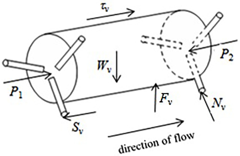
Strained sketch map on the wheeled capsule.
Analysis of the wheeled capsule’s speed changes
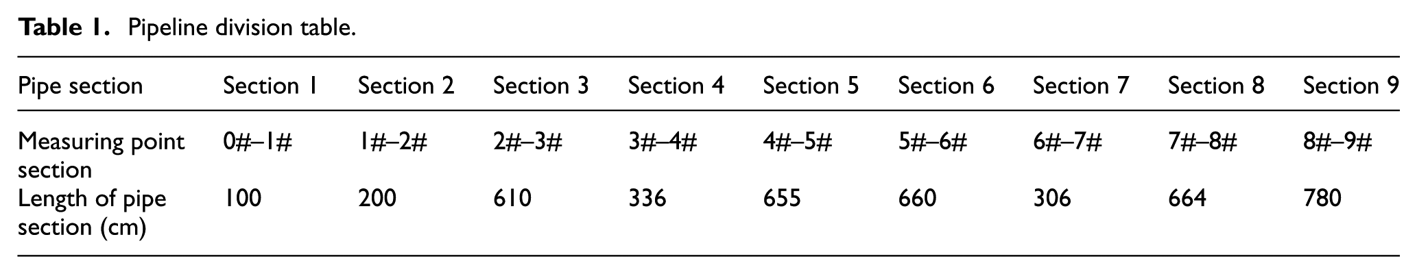
At the starting point, the wheeled capsule was in the stationary state. First, it began to accelerate, then moved steadily and finally detached from the pipeline. The wheeled capsule’s instantaneous running speed was not the same as the overall average speed. As it was difficult to measure the instantaneous running speed, the pipeline was divided into several parts to calculate the average speed of each part to investigate the changes in the wheeled capsule’s speed. The test pipeline was divided into nine parts to study the speed changes of each pipe section. Pipeline division is listed in Table 1. Test point arrangement is shown in Figure 2.
Pipeline division table.
Taking the wheeled capsules with a length (L) and diameter (d) of 150 mm × 80 mm, 150 mm × 70 mm, and 100 mm × 80 mm as examples, the wheeled capsule’s speed changes were analyzed in each pipe section at the mass of transporting materials (M) of 1200 g and 1500g and the water discharges (Q) of 40 m3/h and 70 m3/h. The results are shown in Figure 5, where  and ▴ represent the average speed of the wheeled capsule in each pipe section under different water discharge conditions represents the overall average speed of the wheeled capsule between different pipe sections. It can be seen that
In the study pipe, the running speed of the wheeled capsule in each pipe did not change much and basically fluctuated near the wheeled capsule’s overall average speed. The fluctuation in the anterior pipe sections was large, while the fluctuation in the posterior pipe sections was small. The maximal fluctuation values both appear in the “Introduction” section, and the maximal relative value was no more than 8.6%. The wheeled capsule was fixed at the starting point. After a sudden release, the wheeled capsule began to run. The speed of the wheeled capsule accelerated from zero to the above average speed; therefore, the running speed of the wheeled capsule in Section 1 was more, and the time to accelerate was very short. When the wheeled capsule began to run, the relative speed between the annular gap flow and the wheeled capsule kept changing, thereby constantly changing the mechanical characteristics of the wheeled capsule. When the average speed of the annular gap flow between the wheeled capsule and the pipe wall was more than the average speed of the wheeled capsule, the direction of the shear stress of the wall surface on the wheeled capsule was consistent with that of the flow, and the shear stress acted as a driving force. However, when the average speed of the annular gap flow between the wheeled capsule and the pipe wall was less than the average speed of the wheeled capsule, the direction of the shear stress was opposite to that of the wheeled capsule, and the shear stress acted as a resistance. These changes actually fluctuated the motion of the wheeled capsule between accelerated and retarded motion, thus varying the running speeds of the wheeled capsule in each pipe near the overall average speed of the wheeled capsule. The wheeled capsule took some time to achieve a constant speed; therefore, the fluctuation in the anterior pipe sections was larger than that in the posterior pipe sections.
The speed of the wheeled capsule fluctuated slightly in the anterior pipe sections, and subsequently became constant, indicating that the overall average speed of the wheeled capsule basically reflected the operation conditions of the wheeled capsule. Therefore, in the study pipe sections, the overall average speed of the wheeled capsule was used to analyze its motion characteristics.
The fluctuation in the running speed of the wheeled capsule in each pipe section related to the water discharge, the dimension of the wheeled capsule and the mass of transporting materials. Under different transportation conditions, the running speed of the wheeled capsule in each pipe section fluctuated to different extents.
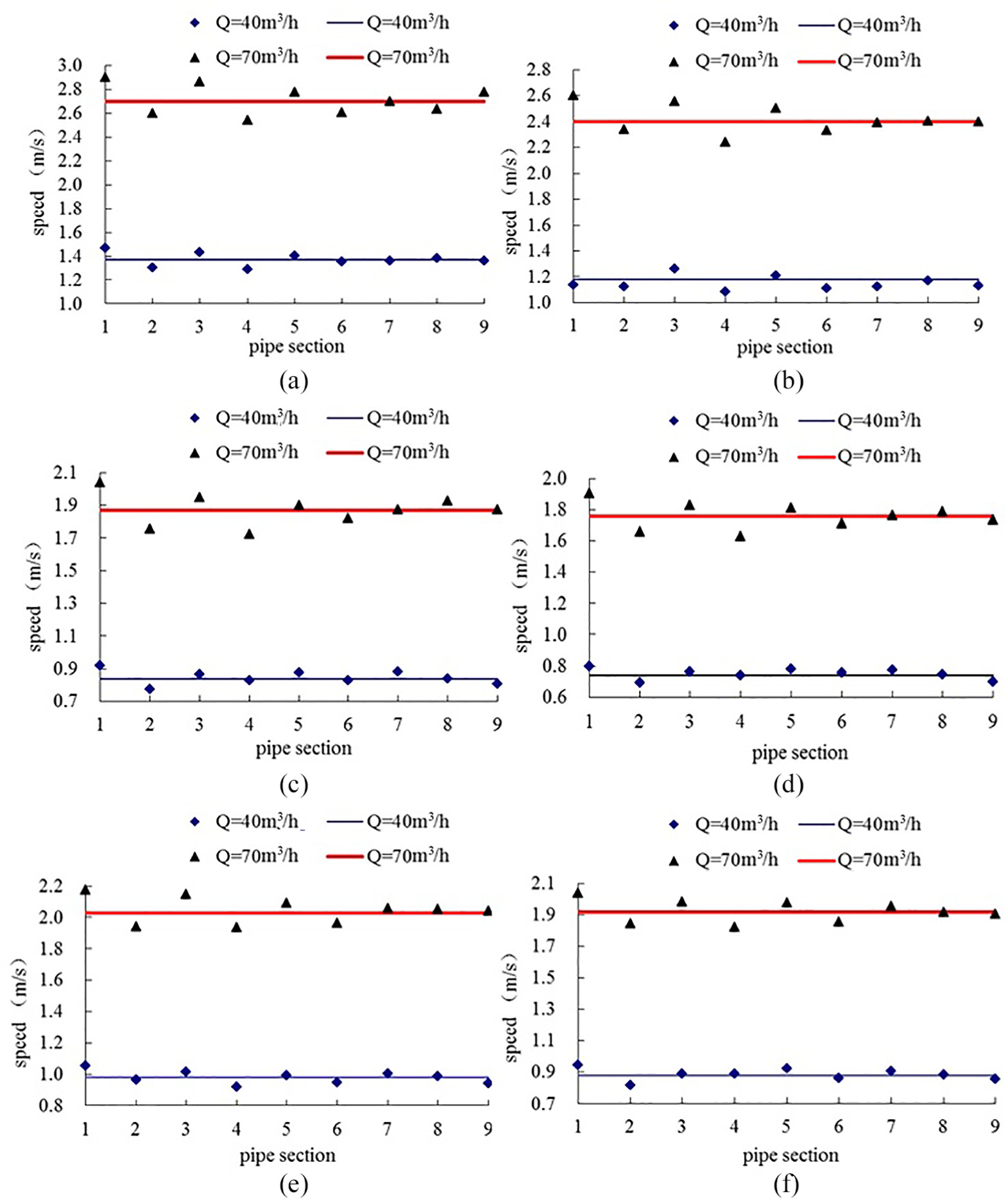
Speed changes of the wheeled capsule in different pipe sections. (a) L × d = 150 × 80; M = 1200 g. (b) L × d = 150 × 80; M = 1500 g. (c) L × d = 150 × 70; M = 1200 g. (d) L × d = 150 × 70; M = 1500 g. (e) L × d = 100 × 80; M = 1200 g. (f) L × d = 100 × 80; M = 1500 g.
The slip velocity during the movement of the wheeled capsule
In the transportation of the wheeled capsule, the annular gap flow formed with a certain length of internal dynamic boundary in the pipeline. Because the speed of the wheeled capsule was different from the annular gap flow, there was relative motion between them, called as the slip velocity. The slip velocity was the difference between the average speed of annular gap flow and the average speed of the wheeled capsule. According to the force analysis of the wheeled capsule, the shear force along the wheeled capsule was one of the main factors affecting the motion characteristics of the wheeled capsule. Moreover, the shear force along the wheeled capsule was related to the slip velocity according to equation (5). Therefore, the slip velocity was used in this study for providing evidence for analyzing the magnitude and direction of the shear force along the wheeled capsule.
Considering wheeled capsules with the lengths and diameters of 150 mm × 80 mm, 150 mm × 70 mm, 150 mm × 60 mm, and 150 mm × 50 mm, the changes in the slip velocity with the water discharge were analyzed at the mass of transporting materials of 1150 g and 1250 g. Result shown in Figure 6 indicates that
The slip velocity is related to the dimension of the wheeled capsule, the water discharge, and the mass of transporting materials. With increasing water discharge, the slip velocity tended to decrease. At the intersection of the curve and the axis of abscissa, the slip velocity was zero, namely, no slip occurred between the annular gap flow and the wheeled capsule. Under the same mass of transporting materials, the position of the intersection of the curve and the axis of abscissa was different for different dimensions of the wheeled capsules. When the dimension of the wheeled capsule, namely, L × d was 150 mm × 80 mm, the intersection of the curve and the axis of abscissa were the nearest, while when the dimension of the wheeled capsule (L × d) was150 mm × 50 mm, the intersection of the curve and the axis of abscissa was the farthest. These observations clearly indicated that the wheeled capsules with different dimensions needed different amounts of energy offered by the flow under movement. The larger the diameter of the wheeled capsule was, the smaller the amount of energy offered by the flow it required. For the wheeled capsule with the same dimension, the position of the intersection of the curve and the axis of abscissa were different because of different mass of transporting materials. The heavier mass of transporting materials was, the farther the intersection of the curve and the axis of abscissa were, indicating that the heavier mass of transporting materials was, the more energy offered by the flow it required.
Figure 6 shows that the changes in the slip velocity with the water discharge reflect the relation between the average speeds of the annular gap flow and the wheeled capsule. The slip velocity is the difference between the average speeds of the annular gap flow and the wheeled capsule. Before the slip velocity was 0, the average speed of the annular gap flow was higher than the average speed of the wheeled capsule. Meanwhile, the direction of the shear stress acting on the wheeled capsule from the wall surface was consistent with the moving direction of the wheeled capsule (in the direction of the flow), and the shear stress was the power for the movement of the wheeled capsule. When the slip velocity was 0, the average speed of the annular gap flow was equal to the average speed of the wheeled capsule, and the shear stress acting on the wheeled capsule from the wall surface was 0. After the slip velocity was 0, the average speed of the annular gap flow was less than the average speed of the wheeled capsule, the direction of the shear stress acting on the wheeled capsule from the wall surface was opposite to the motion direction of the wheeled capsule (opposite to the direction of the flow), and the shear stress resisted to the movement of the wheeled capsule.
Figure 6 shows the trend of the slip velocity with the water discharge, reflecting the changes in the shear stress indirectly. For the wheeled capsule with the same dimension (the wheeled capsule with the same surface area), equation (5) shows that the shear stress is proportional to the square of the slip velocity. Besides, the changes in the slip velocity with the water discharge in Figure 6 show that the square of the slip velocity showed a decreasing trend first, followed by an increase with increasing water discharge. It reflected that the shear stress acting on the wheeled capsule from the wall surface first showed a decreasing trend, and then increasing, indicating that the shear stress acting on the wheeled capsule from the wall surface gradually changed the power into the resistance.

Changed curves of slip velocity in the different water discharges. (a) M = 1150 g. (b) M = 1250 g.
Relationship between the average speed of the wheeled capsule and the water discharge
Taking the wheeled capsules with the lengths and diameters of 150 mm × 80 mm, and 100 mm × 70 mm as examples, the changes in the average speed of the wheeled capsule with different water discharges were analyzed at the mass of transporting materials of 1200 g and 1500 g. The result is shown in Figure 7, indicating that
For the same dimension of wheeled capsule with the same the mass of transporting materials, the average speed of the wheeled capsule increased with increasing water discharge. The main reason is that the power of the wheeled capsule hydraulic transportation mainly originates from the pressure gradient force △P acting on the front and rear end faces of the wheeled capsule. △P was positively correlated with the water discharge. With increasing water discharge, △P increased and the power exerting on the wheeled capsule increased, increasing the average speed of the wheeled capsule.
The fitting of the average speed of the wheeled capsule and the water discharge shows a positive linear relationship. Larger the diameter of the wheeled capsule was, greater the length of the wheeled capsule was, the greater the variation in the average speed of the wheeled capsule with the water discharge was. Furthermore, the fitted formulas of the average speed of the wheeled capsule and the water discharge show the incipient speed of the wheeled capsule. Under the same transportation conditions, the larger the diameter of the wheeled capsule was and the greater the length of the wheeled capsule was, lower the incipient speed was, while the heavier the mass of transporting materials was, the higher the incipient speed of the wheeled capsule was.

Relation between the average speed of the wheeled capsule and water discharge. (a) M = 1200 g. (b) M = 1500 g.
Relationship between the dimension of the wheeled capsule and its average speed
When the mass of transporting materials (M) were 1150 g and 1250 g and the water discharges (Q) were 40 m3/h and 70 m3/h, the changes in the average velocities of the wheeled capsules with different dimensions are shown in Figure 8.

Relation between the average speeds and the different dimensions of the wheeled capsules. (a) M = 1150 g. (b) M = 1250 g.
Figure 8 shows that the length of the wheeled capsule and its diameter were important factors, affecting the speed of the wheeled capsule. Under the same mass of transporting materials and water discharge, the dimension of the wheeled capsule directly affected the buoyancy (it related to the volume of the wheeled capsule), pressure gradient force (it related to the diameter of the wheeled capsule) and the shear stress (it related to the diameter of the wheeled capsule d and its length L), which acted on the wheeled capsule, further affecting the friction acting on the wheeled capsule. The stress analysis of the wheeled capsule shows that whether the diameter of the wheeled capsule d or its length L increased, the buoyancy that acted on the wheeled capsule increased. In addition, equation (3) shows that the friction f acting on the wheeled capsule decreased. The larger the diameter of the wheeled capsule d was, the greater the lateral area of the wheeled capsule was; therefore, according to equation (4), the greater the pressure gradient force acting on the wheeled capsule was. The larger the diameter of the wheeled capsule d and the greater its length L were, the larger the lateral area of the wheeled capsule was. The wall surface shear stress was proportional to the lateral area of the wheeled capsule, indicating that the larger the lateral area of the wheeled capsule was, the greater the shear stress acting on the wheeled capsule was according to equation (5). Figure 8 simultaneously shows that the effect of the diameter of the wheeled capsule on the average speed of the wheeled capsule was greater than that of the length of the wheeled capsule. Therefore, after comprehensively comparing the force conditions of the wheeled capsules with eight dimensions, the average velocities of the wheeled capsules with eight dimensions were in the order of 150mm×80mm>100mm×80mm>150mm×70mm>100mm×70mm>150mm×60mm>100mm×60mm >150mm×50 mm > 100 mm × 50 mm.
Relationship between the mass of transporting materials and the average speed of the wheeled capsule
Taking the wheeled capsules with L × d of 150 mm × 80 mm and 100 mm × 70 mm as examples, the changes in the average speed of the wheeled capsule with different the mass of transporting materials were analyzed at the water discharges (Q) of 40 m3/h and 70 m3/h. The result is shown in Figure 9, indicating that
Under the same water discharge condition, the average speed of the same dimension of wheeled capsule decreased with increasing the mass of transporting materials. The reason was mainly based on the fact that if the other transporting conditions remained unchanged, the change in the mass of transporting materials just changed the frictional resistance acting on the wheeled capsule. The heavier the mass of transporting materials was, the greater the frictional resistance was, resulting in a decrease in the average speed of the wheeled capsule.
The fitted formulas of the average speed of the wheeled capsule and the mass of transporting materials show a negative linear correlation between the average speed of the wheeled capsule and the mass of transporting materials, and the larger the water discharge was, the greater the variation in the average speed of the wheeled capsule with the mass of transporting materials was.

Relation between the average speeds of the wheeled capsules and the mass of transporting materials.(a) L × d = 150 × 80. (b) L × d = 100 × 70.
Empirical formula for the average speed of the wheeled capsule
According to the experimental results of the wheeled capsule’s average speeds with different water discharges, wheeled capsule dimensions and mass of transporting materials, the average speeds of the wheeled capsules were fitted by the nonlinear regression method. Therefore, the empirical formula of the average speed of the wheeled capsule was obtained, which can be expressed as follows

where
The comparison between the wheeled capsule speed calculated according to equation (6) and the wheeled capsule speed obtained from the test listed in Table 2 indicates good agreement between the calculated value of the wheeled capsule speed with the experimental value, and the maximum relative error did not exceed 7.05%, confirming that the empirical formula of the wheeled capsule speed obtained from the test fitting was feasible.
Comparison of the calculated and experimental values of the average speeds of the wheeled capsules.

The wheeled capsule hydraulic transportation is a transporting technique in which the pressurized flow acting on the wheeled capsule pushes the wheeled capsule to move forward. As the conveying carrier of the wheeled capsule, the flow provides power for the movement of the wheeled capsule. Consequently, the physical characteristics of the conveying flow are also one of the key factors affecting the motion characteristics of the wheeled capsule. The changes in the temperature or water quality of the conveying flow will affect the motion characteristics of the wheeled capsule to a certain extent. In this study, the motion characteristics of the wheeled capsule under normal temperature and clear conveying flow were experimentally investigated.
Conclusion
The conclusions of this study are as follows:
The study pipe was divided into nine parts, and the speed of the wheeled capsule in each pipeline section was analyzed. In each pipe section, the speed of the wheeled capsule basically fluctuates near the overall average speed of the wheeled capsule and the maximum relative fluctuation value is no more than 8.6%. Therefore, the overall average speed of the wheeled capsule can be used to analyze the motion characteristics of the wheeled capsule in the study pipe.
The absolute value of the slip velocity increases first and then decreases with increasing water discharge. When the diameter of the wheeled capsule decreases, or the mass of transporting materials increases, the water discharge corresponding to the minimum value of the slip velocity increases. Moreover, the trend in the changes in the slip velocity also reflects the trend of changes in the shear stress of the wall surface on the wheeled capsule and its direction when the wheeled capsule moves.
When the water discharge, the diameter or length of the wheeled capsule increases, or the mass of transporting materials decreases, the speed of the wheeled capsule increases.
The empirical formula of the average speed of the wheeled capsule with different water discharges, wheeled capsule dimensions, and mass of transporting materials was obtained by the nonlinear regression method. The empirical formula was validated by experiments. The maximum relative error did not exceed 7.05%, proving that the empirical formula is feasible.
Footnotes
Handling Editor: James Baldwin
Declaration of conflicting interests
The author(s) declared no potential conflicts of interest with respect to the research, authorship, and/or publication of this article.
Funding
The author(s) disclosed receipt of the following financial support for the research, authorship, and/or publication of this article: This project is supported by National Natural Science Foundation of China (No.51179116) and Shanxi Provincial Natural Science Foundation of China (No.201701D221137).