
Abstract
Ultra-high-speed permanent magnet synchronous motors usually adopt the rotor in which a sleeve is interference fitted onto a ring permanent magnet or segmental permanent magnets. The rotors are always subject to the extreme working condition (e.g. high speed and high temperature). In order to predict the strength of the rotor, this article proposes analytical models considering three types of stress sources such as interference fit, centrifugal force, and temperature gradient. Examples are calculated and discussed. Results show that the effect of the temperature gradient on sleeve stresses is slight; however, the influence of the temperature gradient on stresses of the permanent magnet and shaft is dramatic; for the rotor with a outer surface forced air cooling, the shaft will generate a large radial expansion which causes a addition pressure effect on the permanent magnet and sleeve to prevent loosening and stripping of the interfaces. Moreover, segmental permanent magnets are helpful to reduce stress. The study will give a useful hint for the optimal design and manufacture of the ultra-high-speed permanent magnet rotor.
Keywords
Introduction
High-speed or ultra-high-speed permanent magnet synchronous motors (PMSMs) have a strong trend of application in modern industry due to those simple structures and high power density.1,2 For high-speed motors or generators, the rotor speed is normally above 30,000 r/min even may exceed 100,000 r/min. Designs of such high-speed machines are quite different from the low speed and low frequency ones. Especially, the structure design and strength analysis of the permanent magnet (PM) rotor are extremely important to the reliable operation of high-speed machines. 2
High-speed rotors request a sleeve to fasten the components to against the centrifugal force. Metallic or fiber-reinforced sleeve is widely adopted in high-speed rotors. For the fiber-reinforced sleeve which is usually made from carbon/glass fiber, it will withstand a minor centrifugal force due to their low density relative to that of metallic. However, unfortunately fibrous sleeve do not has its superior strengths in all directions, their radial strength is very weak and almost up to 30 times lower than that of the circumferential.3,4 Although the stress solution of a single-layer ring is given in the literature, 5 the main literatures available in the bibliography are preliminarily limited to flywheel rotors,6–8 with a few publications about ultra-high-speed PM rotor. In general, high-speed flywheel rotors are multi-layer composite structures which are assembled by fiber-reinforced sleeves. From the point of view of the rotor strength, some differences between metallic sleeve and fiber-reinforced sleeve are as follows:
Comparing with the metallic sleeve, fiber-reinforced sleeves are unable to generate eddy current loss, but have a smaller thermal conductivity, which makes the heat dissipation of the rotor difficult by a surface cooling. 9 Although eddy current will be inducted in the metallic sleeve, the metallic sleeve has a large thermal conductivity that contributes to cooling; meanwhile, it has a large bending stiffness to improve the critical speed. In fact, proper eddy loss offers a great damping to eliminate the circumferential vibration of the rotor due to the power-angle oscillation.
Fiber-reinforced sleeve is very thin in general and can be considered as a “thin shell.”3,10 Specially, the material is anisotropic. But metallic sleeve is too thick that can be treated as “thick-shell” and the material is isotropic.
Before axial pressing or shrinking onto the rotor, adjusting the sizes of the fiber-reinforced sleeve, for example, its inner radius and axial length, is easy to achieve a defined pre-stress. 10 However, for the rotor owning metallic sleeve, the initial compression stress at the interface is unknown and needs a complex solution.
For the two-/three-layer rotor with an embedded circular/ring shaped PM, literature11,12 proposes the analytical formulas to estimate the strength without consideration of temperature effects. Literature 13 studies the influences of the axial pressure and temperature on rotor strength, but temperature gradient is neglected. Strength of thermal carbon-fiber retaining rotor in the surface-mounted high-speed PM machine is analyzed.9,14 For given heat sources of the rotor and cooling condition, the solution to the temperature field of the rotor can refer to the analytical model. 15
At present, for the metallic rotor, there are few literatures refer to the temperature gradient effects, which may exert vital influence on the rotor strength. Moreover, the PM sometimes is splitted into two or more pieces in circumferential direction during fabrication, but few studies involve the rotors owning segmental PMs. In the paper, temperature gradient and segmental PM effects on the rotor strength will be studied analytically, corresponding simulations by finite element method (FEM) will be carried out for comparison analysis, and some useful design guidelines will be generalized.
Analytical model
As depicted in Figure 1, ultra-high-speed rotors generally adopt interference fit joints in which sleeves are interference fitted onto ring PM (Figure 1(a)) or segmental PMs (Figure 1(b)). To facilitate assembly, PM is cut off along the axial direction and then fastened to the outer surface of the shaft. In fact, there is a small axial gap between the PM and the shaft to make sure that the PM is pressed into the shaft smoothly. In the assembly, the inner surfaces and ends of the segmental PMs will be coated with mucilage to fill the gaps of PM–PM and PM–shaft. The rotor will be magnetized as a whole after the sleeve is interference fitted onto the PMs. In general, thermal expansivity of the shaft is larger than that of the PM. Moreover, the temperature of the shaft is higher than that of the PM, due to forced air cooling of the rotor by the stator–rotor narrow gap. Hereupon, when the rotor temperature rises, the elongation of the shaft is larger than that of the PM, and the axial extrusion effect between the PM and the shaft is so weak that the axial stress can be ignored. Even though an axial temperature gradient appears, the maximal rotor temperature occurs at the outlet. Therefore, it just needs to consider the cross section of the rotor at the outlet in checking the thermal stress. A hollow shaft is also used to reduce the weight or to serve as a passage of cooling air or nutted rod. When the material of the shaft chooses PM, then the three-layer rotor will be simplified to the two-layer rotor. As shown in Figure 1, parameters belong to PM; sleeve and shaft are represented by subscripts 1, 2, and 3, respectively. Subscripts i, a denote the parameters of the inner and outer radius accordingly, for example, r1i, r1a denote the inner and outer radius of the PM, and r2i, r2a, r3i, r3a have similar meanings. P1 and P2 are the radial stress at the interfaces of PM–sleeve and PM–shaft, respectively. The above rotor structures are widely applied in many industrial fields, for example, the high-speed brushless direct current Motor (BLDC) motor of 50 kW, 70,000 r/min class centrifugal compressor, 16 120 kW, 70,000 r/min high-speed PM alternator for microturbine applications17,18 and ultra-high-speed motor for air blower cooling fuel cells. 19

Ultra-high-speed PM rotors: (a) ring PM rotor and (b) segmental PM rotor.
Governing equation
Considering the temperature effect, the geometric equation 20 becomes

where
Constitutive equation 20 of the material is

where E is Young’s modulus of elasticity,


where

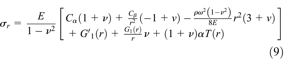
Substituting equation (4) into equation (3a), we obtain equation (5)

where

According to equation (6), there are

where
where


Inferring from equations (9) and (10), the two undetermined coefficients of the PM can be denoted by
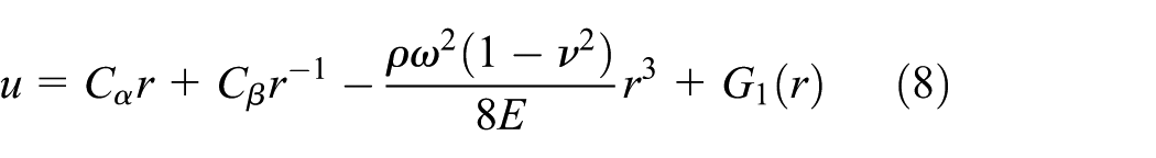
Integrate equation (3b) directly, we obtain
For the displacement field of the PM, it has
where
Boundary conditions and matrix equation
As to the rotor with solid shaft shown in Figure 1, boundary conditions are given by the following

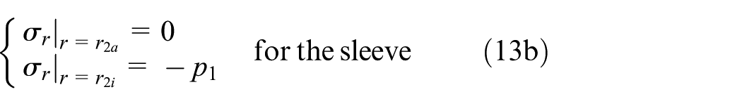

where

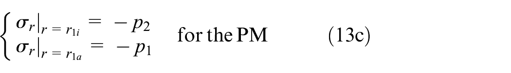
where coefficients
Boundary conditions of the rotor with hollow shaft are mostly the same as those of solid rotor except that
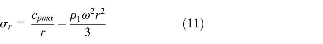
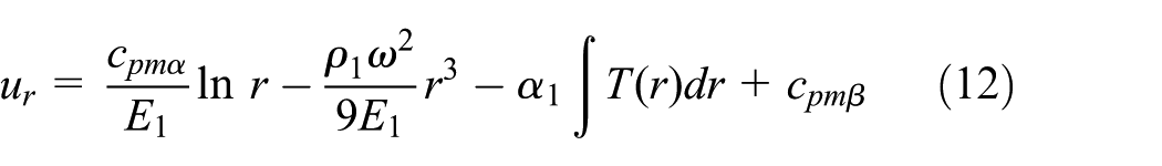
The stress and displacement field of the segmental PM are given by equations (11) and (12), respectively. The boundary conditions equation (13) is universal for the shrink fit of the three-layer rotor. There is a only a difference between solving the stress of the rotor with segmental PM and the one with ring PM, that is, the operation that
Examples
As the rotor shown in Figure 1(a), the paper gives an example in which the materials of the PM, sleeve, and shaft are Sm2Co17, Ti6Al4V, and 40Cr, respectively. Material properties and sizes of the rotor in the example are listed in Tables 1 and 2, respectively.
Material properties of rotor.

Sizes of the rotors.

Ununiform temperature
The rated parameters of a three-phase motor are power 14 kW, voltage 200 Vrms, current 45 Arms, frequency 2000 Hz, and air-gap flux density 0.3 Tave. In the rated duty, stator iron loss, stator copper loss, rotor eddy current loss, and rotor windage loss are 500, 245, 201, and 35 W, respectively. Rotor eddy current loss and windage loss are mainly concentrated in the sleeve due to the skin effect; therefore, heat generation rates of the stator iron, windings, and sleeve are 1.94 × 10⁶, 0.8 × 10⁶, and 14.45 × 10⁶, respectively. A water cooled jacket is applied to cool the stator and the corresponding convection heat transfer coefficient is 533 W/(m2 K), and the inlet temperature of the water is 293 K. Air is blown into the gap between the stator and the rotor to cool the rotor, the equivalent convection heat transfer coefficient is 200 W/(m2 K), and the inlet temperature of the air is 293 K. The steady temperature field of the rotor of the FE thermal model is shown in Figure 2(a) where the temperature inside the rotor is maximum (466.6 K), and the temperature on the rotor surface is minimum (458.9 K). In addition, the temperature in most parts of the rotor is uniform, but has a considerable gradient in the PM and sleeve, due to forced air cooling of the rotor by the stator–rotor narrow gap. Rotor temperature distribution along the radius is illustrated in Figure 2(b).

Rotor ununiform temperature field: (a) rotor temperature field contour of the FE model and (b) rotor temperature field curve.
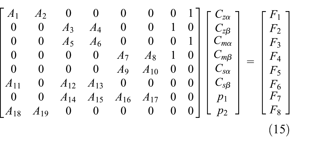
The ANSYS software is applied to build the FE strength model in which the rotor uses solid186 element and the two interfaces adopt frictional contact. Outer surfaces of the PM and the shaft use target170 element, and inner surfaces of the PM and the sleeve apply conta174 element. The rotor is set to rotate at an angular velocity, in order to prevent the rigid motion of the rotor, the sleeve is constrained by four low stiffness springs built by combin14 element. Interference fit can either be set in the contact pair or be generated by the size interference. Under the combining effects of a 120,000 r/min speed, an initial interference 100 μm and the temperature field in Figure 2(b), the comparison between the analytic solution and the FE solution is shown in Figure 3, which displays the agreement of results by the two methods. It shows that radial stress of the PM equals −90 MPa, which indicates the PM is still under pressure; however, the circumferential stress of the PM is positive, which means the circumferential of the PM is in the tension state. It concludes that although the PM is expanding outward, it is still in extrusion by the sleeve, which means that interface of PM–sleeve does not get loose.
Comparison of rotor stress considering temperature gradient: (a) comparison of PM stress, (b) comparison of sleeve stress, and (c) comparison of shaft stress.
Figure 3(b) shows that elements of the sleeve are compressed in the radial direction but stretched in the circumferential direction, the circumferential stress at inner radius of the sleeve is maximum (800 MPa), but it still within the elastic limit.Figure 3(c) shows that the distribution of radial and circumferential stress is approximately same, and both are negative, which means the shaft is in compression yet. The error in Figure 3 may be caused by the followings: (1) the outer surface of the sleeve is restrained by four springs, although the stiffness of the spring is much smaller than the structural stiffness of the sleeve, it will still have some influence on the simulation results; (2) in the FE model, the friction coefficient between the interfaces is taken into account, but this factor is not considered in the analytical solution. Figure 4 shows the stress contour by FE model; the data points of the FEM selected for the comparison are chosen at the areas away from the stress concentration region which caused by weak springs, as shown in Figure 4(a).
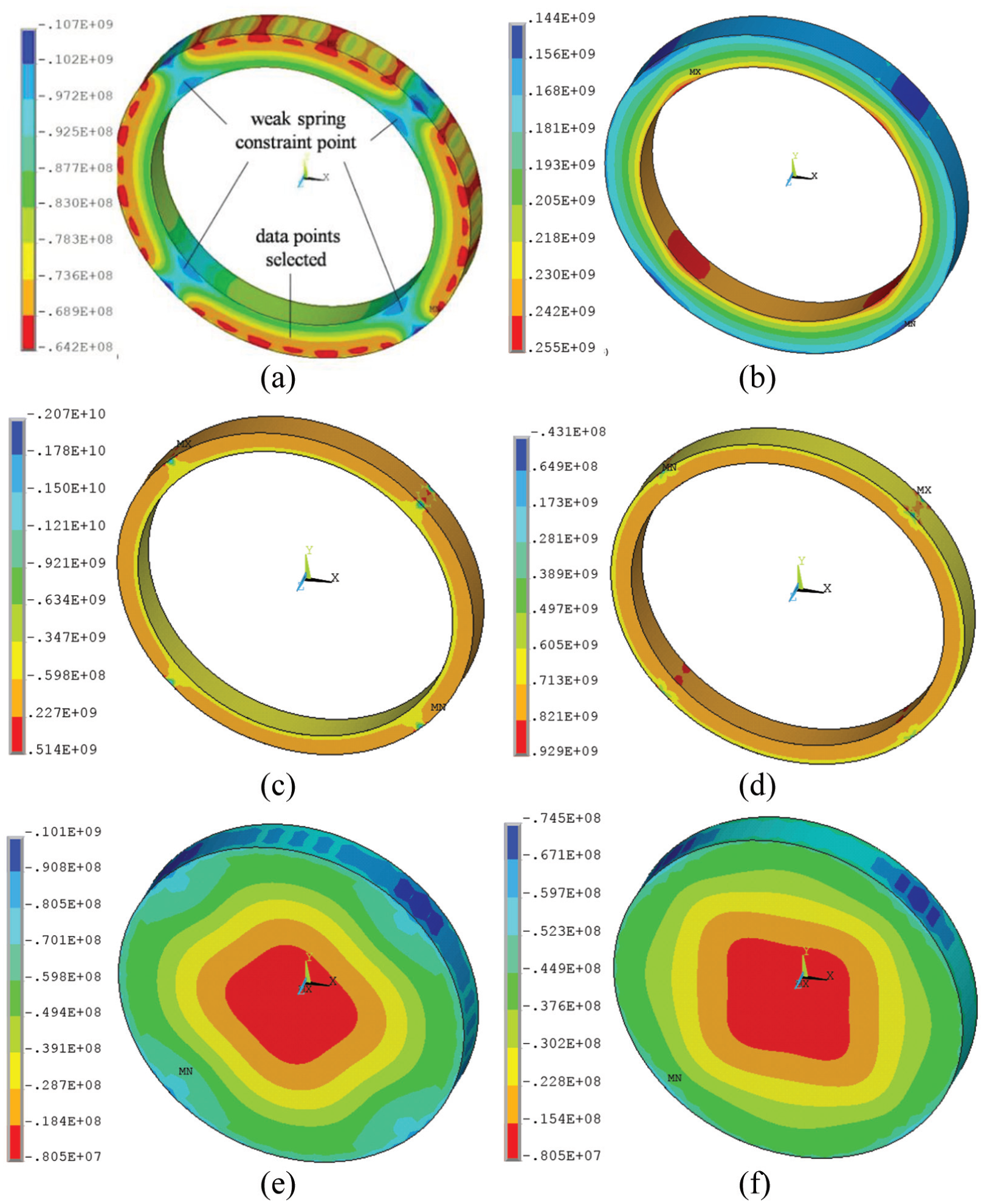
Rotor stress contour of FE model: (a) radial stress of the PM, (b) circumferential stress of the PM, (c) radial stress of the sleeve, (d) circumferential stress of the sleeve, (e) radial stress of the shaft, and (f) circumferential stress of the shaft.
Uniform temperature versus ununiform temperature
The uniform temperature field is shown in Figure 5(a) where the temperature is 466.6 K, and the comparison between the solutions to the uniform and ununiform temperature is shown in Figure 5(b)–(d). As shown in Figure 5(b), for the PM in the rotor with temperature gradient, its radial stress and circumferential stress are 20 MPa larger than and 20 MPa smaller than the corresponding one without temperature gradient, respectively. The above phenomenon is because that the materials near the rotor outer surface have a small radial expansion because of their relative small thermal expansion coefficients and low temperature; however, the shaft has a large radial expansion attributing to its large thermal expansion coefficient and high temperature; hence, the relative expansive shaft causes an addition pressure effect on the PM to increase the radial stress. In addition, because the bulk temperature of Figure 2(b) is lower than that of Figure 5(a), the rotor with temperature gradient has a relative weak expansion effect, which results in that the circumferential stresses of the PM and sleeve are lower than the ones with uniform temperature field, as shown in Figure 5(b) and (c).
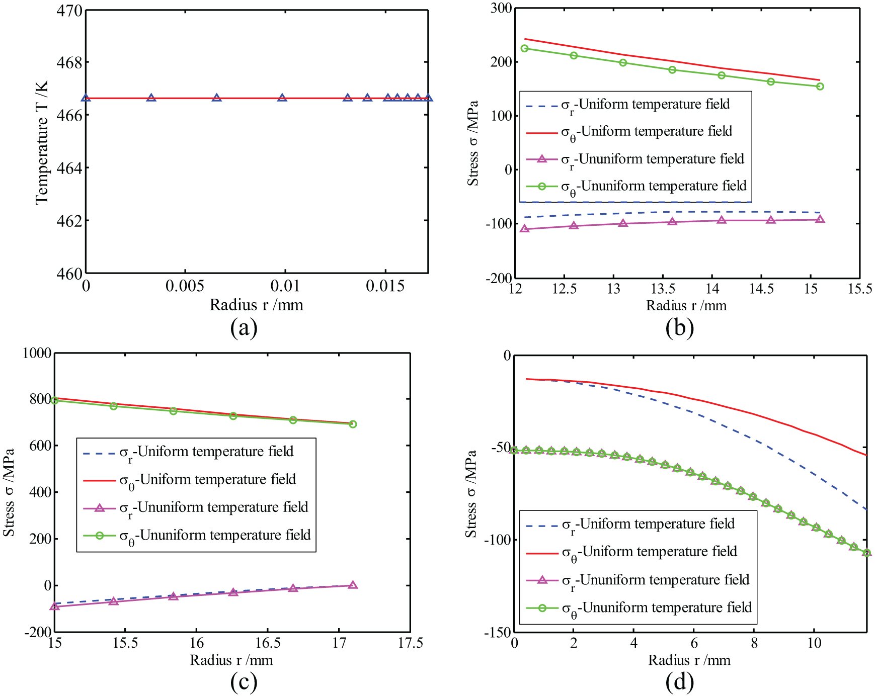
Results comparison of uniform and ununiform temperature field: (a) uniform temperature field curve of the rotor, (b) comparison of PM stresses, (c) comparison of sleeve stresses, and (d) comparison of shaft stresses.
Figure 5(c) shows that sleeve stresses under the uniform temperature field are very close to that under the ununiform temperature field, which indicates that sleeve stresses are mainly caused by the initial interference and centrifugal force, and the effect of the temperature gradient on sleeve stresses is slight. According to the principle of action and reaction, the PM also exerts an additional pressure on the shaft, which leads to an increase of the radial compressive stress of the shaft. Compared with the uniform temperature field, the inward radial expansions of the PM and the sleeve under temperature gradient are small, which makes the shaft has a larger outward radial expansion, so the circumferential stress of the shaft is larger than that of the uniform temperature field as shown in Figure 5(d).
Segmental PM effects
For the rotor shown in Figure 1(b), the sizes are given by Table 2 and the angle of the seam is 4°. The material of the sleeve is inconel718 and the initial interference is 50 µm. In order to reveal segmental PM effects, the rotor is subjected to a uniform temperature field (293 K); results are shown as following.
Figure 6 shows that for the rotor at 0 r/min, analytical solutions agree well with numerical solutions except a slight difference in circumferential stress, namely, 20 and 0 MPa are obtained by FE model and analytical model, respectively. When the rotor speed increases to a 90,000 r/min, FE results display that the circumference stresses near inner surface and outer surface of the segmental PM equal 0 and −10 MPa, respectively. It seems that the circumference stress of the segmental PM will approach gradually to 0 MPa when the rotor speed increases, the above phenomenon is consistent with the assumption proposed in the analytical model.

Distribution of the stress in the PM.
It is worth noting that the above numerical solutions are extracted from the interior face, as shown in Figure 7(a), which is far from the seam constructed by side faces of two segmental PMs. In fact, stress concentration occurs around the seam. For example, as shown in Figure 7(b), comparing with the Von Mises stress at the inner surface near the interior face, those near the seam have a 10.7% increment.
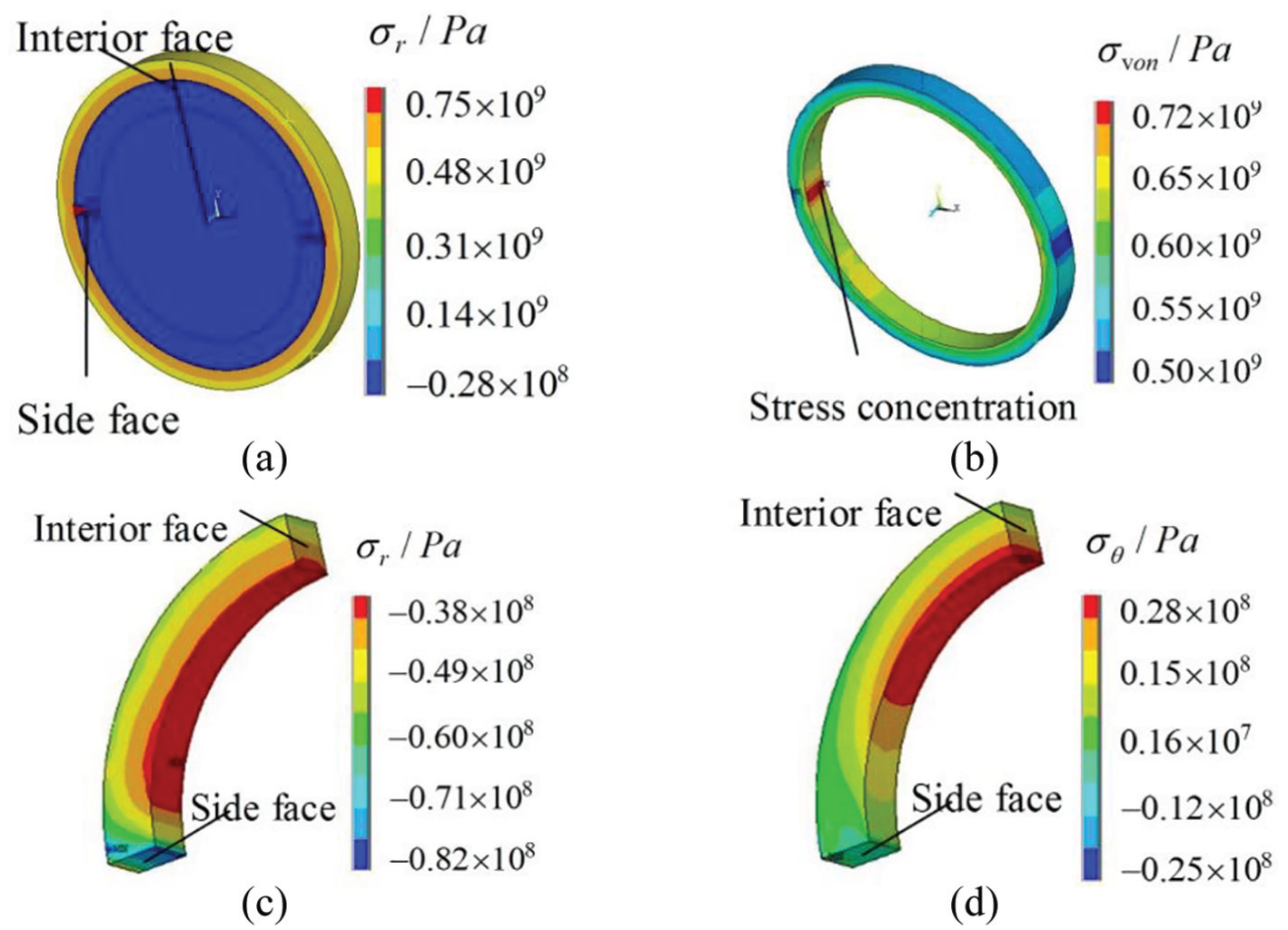
Stresses of the rotor with segmental PM (90,000 r/min, 293 K): (a) σθ of the rotor, (b) σvon of the sleeve, (c) σr of the PM, and (d) σθ of the PM.
Figure 7(c) and (d) shows the distributions of the residue radial stress and the circumference stress in a half segmental PM, respectively. In Figure 7(c), the distribution is uniform except a local stress concentration near the side face, which means that ends of the segmental PM have an enhanced extrusion effect. In Figure 7(d), the circumference stress is very small in most of region except a local stress concentration close to the intermediate section near the inner surface.
Without considering the stress concentration, Von Mises stress calculated by the analytical model is about 12% larger than that by the FEM at low rotor speed and temperature. However, results obtained from both methods are consistent under high speed and temperature, which validates the proposed analytical model.
The segmental PM can release the circumferential stress by extending self along the circumferential direction; therefore, circumferential tension fracture will not appear in the PMs. There are two extremes, the one is the seams between PMs have nothing, and the other is the seams are filled with hard materials. For the former, the PM stress can be predicted by the analytical solution without considering the stress concentration; for the later, the circumferential extending will be restricted by the hard materials, which leads to a failure of the stress relieving. However, for the low hardness filler, for example, epoxy resin and mucilage, the PM stress will be somewhere between that of the two extremes. The paper only refers to the above two extremes and the effects of filler materials will be considered later.
Conclusion
The paper proposes the strength analytical solution to the ultra-high-speed PM rotor considering three types of stress sources such as interference fit, centrifugal force, and temperature gradient, and the analytical solutions are verified by FEM. Under the combining effects of a 120,000 r/min speed, an initial interference 100 μm, and temperature gradient, the effect of the temperature gradient on sleeve stresses is slight; therefore, sleeve strength can be checked by the uniform temperature. However, the influence of the temperature gradient on stresses of the PM and shaft is dramatic, for the rotor with a outer surface forced air cooling, because the shaft has a large thermal expansion coefficient and a high temperature, it will generate a large radial expansion which causes an addition pressure effect on the PM and sleeve. The above phenomenon will make the radial stress at the interfaces between PM–shaft and PM–sleeve increase to prevent loosening and stripping of the rotor.
For the three-layer composite rotor with segmental PMs, without considering the stress concentration, Von Mises stress calculated by the analytical model is about 12% larger than that obtained by the FEM at low rotor speed and temperature. However, results obtained from both methods are consistent under high speed, which validates the proposed analytical model. It indicates that the ring shaped PM can be cut in circumferential direction into several segmental PMs to eliminate partly the excessive positive radial/circumferential stress due to a high centrifugal force. However, the seam between segmental PMs should be filled with a certain material to decrease the stress concentration caused by edges of segmental PMs.
Footnotes
Appendix 1
Appendix 2
Handling Editor: Shahin Khoddam
Declaration of conflicting interests
The author(s) declared no potential conflicts of interest with respect to the research, authorship, and/or publication of this article.
Funding
The author(s) disclosed receipt of the following financial support for the research, authorship, and/or publication of this article: This work is supported by National Natural Science Foundation of China (Grant Nos 51705413, 51705416, 11502196) and China Postdoctoral Science Foundation (Grant No. 2017M613291XB).