
Abstract
The determination of the initial position plays a crucial role in the sensorless control of motors, significantly affecting the operational performance. Unlike the conventional schemes involving two separate steps, the proposed scheme constructs a closed-loop control system with response current feedback and integrates polarity identification with rotor position tracking through unipolar pulse sequence signal injection to estimate the rotor position. The entire scheme adopts a discrete approach, ensuring a holistic and less complex algorithm. Moreover, a novel iteration method based on interpolation is introduced, leveraging the reconstructed cost function to achieve rapid convergence and minimize the number of injected pulses. This process overcomes the limitation of obtaining accuracy in the conventional pulse signal injection method is related to the number of injected pulse signals and gives the control system extra flexibility. The superiority and feasibility of the proposed scheme are verified on an experimental platform driven by a surface-mounted permanent magnet synchronous motor (SPMSM).
Introduction
Motivation
With the increasing scarcity of global energy resources and the growing demand for energy, electric vehicles (EVs) have become a crucial part of the transportation landscape. In the realm of electric drive systems, permanent magnet synchronous motors (PMSMs) have garnered considerable attention due to their numerous advantages, including higher energy density, reduced torque ripple, and more versatile control techniques.1–5 In conventional motor control, closed-loop control typically requires digital sampling of various motor variables. Incorporating sensors into the control system can undoubtedly increase the complexity of the entire setup, leading to higher economic and spatial costs. To address this dilemma, extensive research on sensorless control solutions has been conducted in the industry.6–11
However, it is crucial to note that in sensorless control schemes, determining the initial position of the rotor becomes a critical step that significantly influences the normal operation of the motor. Therefore, in light of the economic and efficiency considerations associated with sensorless control, it is imperative to further optimize and enhance the methods used for obtaining the initial rotor position.9–17
Related researches
Sensorless control methods can be categorized based on the speed range of the motor. At medium to high speeds, the rotor position can be observed through a significant back electro-motive force (back-EMF) or magnetic linkage generated by permanent magnet induction.18–22 However, at zero speed and low speeds, a different approach is required. In this case, a high-frequency (HF) signal is injected into the fundamental signal and applied to the motor. The resulting response current will contain the rotor position information. By processing this information, the rotor position can be estimated accurately.23–30
Indeed, determining the initial rotor position is a crucial step in sensorless control schemes. Some conventional methods involve forcing the rotor to a preset position by injecting multiple voltage vectors before motor startup. Alternatively, an observer based on back-EMF can be used to track the motor during open-loop startup.31–34 However, both of these methods can disturb the initial stationary state of the motor, leading to adverse effects in practical applications of electrical drives. Therefore, detecting the initial rotor position of a motor at standstill holds significant practical value.
Common methods for determining rotor position at standstill can be classified into two categories: continuous signal injection and discrete signal injection.35–39 Continuous signal injection essentially employs principles similar to rotor position tracking during motor rotation. After obtaining rotor position information, additional polarity identification is necessary to prevent erroneous convergence to the -d-axis or even the q-axis. Polarity identification methods fall into three categories: pulse injection, HF current amplitude change, and secondary significance. Pulse injection, due to its straightforward principle and operation, is widely used. This method capitalizes on the magnetic saturation effect of the stator and rotor cores, which remains a crucial step in most conventional initial position determination schemes.
Continuous signal injection in rotor position determination typically is HF signal injection (HFSI), which can be categorized into rotating signal and pulse signal injection based on signal waveform. In the context of HF pulse signals, square wave signals have been extensively studied. In Ref., 40 HF sinusoidal signals were injected into the virtual d-axis of the motor, and motor oscillation was measured using a vibration detector to track rotor position. However, limitations in the response speed and detection frequency of the vibration sensor resulted in extended measurement times. In Ref., 41 a novel approach combining sinusoidal and square wave injections was proposed. It harnessed the magnetic saturation effect of the motor via sinusoidal signal injection and integrated d-axis current through square wave signal injection, facilitating polarity identification based on integral outcomes. In Ref., 42 to mitigate noise from HF signal injection, square wave signals underwent pseudorandom processing. Moreover, to address delay in polarity identification, a method involving saturation peak current delay compensation was introduced, significantly enhancing overall estimation effectiveness.
In discrete pulse signal injection, multiple pulses are used to achieve the desired estimation accuracy and conduct rotor position tracking based on magnetic saturation effects. This approach offers improved robustness, simpler principles, and cost-effective signal generation compared to continuous injection. To overcome the drawbacks of lower accuracy and extended processing times, several enhancements have been proposed. In Ref., 43 six voltage pulse vectors, each with a 60° phase difference, were injected into the stator winding, dividing the rotor space into sectors and achieving a 30° estimation accuracy. However, this method still involves unnecessary signals, resulting in increased time costs for the same accuracy. To address this, another study in Ref. 44 introduced the concept of “boundary width” and a preset error threshold based on external interference to manage ambiguity at sector divisions. With just three pulse signal injections, this approach achieved a 15° rotor position tracking accuracy, significantly improving efficiency, and precision. Reference 45 proposed an innovative four-stage search algorithm based on pulse signal injection, encompassing rough search, polarity identification, descent search, and subtle search. Using a total of 16 pulse signals, this method obtained an approximate rotor position with 0.5° accuracy and demonstrated robustness.
Contributions
This paper introduces a novel pulse signal injection method for unified rotor position tracking and polarity identification at standstill. Compared with the existing methods that increase pulses in exchange for accuracy, this scheme provides high-precision rotor tracking with fewer pulse signals. The proposed scheme has high robustness and low parameter dependence. A surface-mounted PMSM (SPMSM) is used to verify the effectiveness of the proposed scheme. The contributions of this paper can be summarized as follows:
1) Introduction of the principle of rotor initial position detection and polarity identification using HF square wave signal injection, accompanied by an analysis of the limitations of conventional methods.
2) Analysis and reconstruction of the current response after pulse signal injection to address incorrect convergence points, improving the accuracy of rotor position tracking.
3) Introduction of the mathematical iterative method and proposal of a closed-loop unipolar pulse sequence injection method for determining the rotor position. The initial position detection scheme (IPS) calculation module is formed by combining polarity identification and rotor position tracking through this method, resulting in a reduction of the number and execution time of injection pulses, while ensuring excellent estimation accuracy.
Analysis of conventional initial position estimation scheme for PMSMS
Model analysis of PMSMS
The stator of the PMSM discussed in this paper consists of a set of Y-shaped winding and it is referred to as the ABC phase. To analyze the mathematical model, it is assumed to be an ideal motor. Under this condition, the voltage equation and torque equation of the PMSM in the stationary reference frame (SRF) can be expressed as follows46–48:
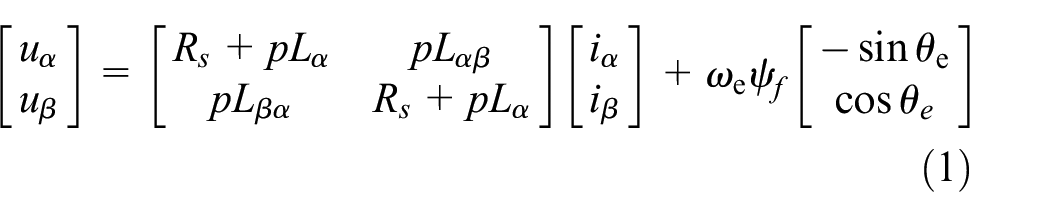
where uα,β, iα,β, and ωe are the voltage, current components of the α-β axis and electrical angular velocity. Rs, Lα,β, and

The analysis of PMSMs needs to be carried out in multiple reference frames. Figure 1 illustrates the relationship between various reference frames employed in PMSMs.

Relationship between various reference frames.
The matrix of rotation transformation can be expressed as follows:

According to Figure 1 and equation (3), the transformation between the model of SRF and the model of the rotating reference frame (RRF) can be achieved.49–52 Furthermore, the voltage equation of the RRF can be expressed as follows:

where ud,q, id,q, and Ld,q are the voltage, current, and inductance components of the d-q axis, respectively.
The electromagnetic torque of the motor can be expressed as follows:
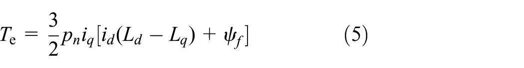
where pn is the pole number of the motor.
The mechanical motion equations of the motor can be expressed as follows:
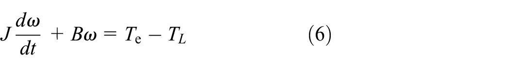
where J, ω, B, and TL are moment of inertia, mechanical speed, damping coefficient, and load torque, respectively.
Conventional initial position tracking method
As mentioned in Part B of Section I, the conventional rotor initial position tracking modules can be classified based on the type of injected HF signal. For SPMSMs, there is Ld = Lq, so it is necessary to consider the feasibility of sensorless control schemes for this type of motor.53–56
Compared with other waveform signals, the square wave signal enables the HF signal injection method to be used not only in interior PMSMs (IPMSMs) with large saliency ratios but also in motors with small saliency ratios and even in SPMSMs.57,58 After considering various options, square wave signals have been proven to be the most effective and optimal choice for HFSI schemes. Therefore, the HFSI initial position identification scheme using HF square wave signals is analyzed as an example. Since the frequency of the injected HF signal is significantly higher than the fundamental frequency of the motor, the components associated with resistance and winding inductance can be neglected. As a result, the voltage equation can be simplified as follows:

where Ldh and Lqh are the inductances under HF signal injection.
In conventional schemes, the HF signal is injected into the estimated d-q axis system to extract the rotor position information.
The coordinate transformation between the estimated and actual rotating reference frames can be expressed as follows:

where

Schematic diagram of maximum rotor error.
The response current when the HF signal is injected can be expressed as follows:
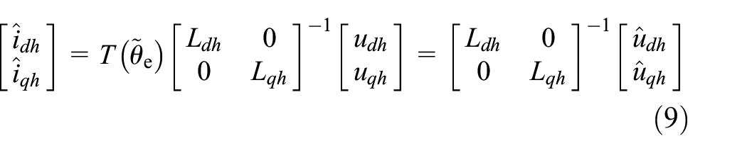
where


where Vinj, n, k, Ts are the amplitude of the injected HF square wave signal, natural numbers, discrete sampling time coefficients, and discrete sampling time, respectively. Therefore, the current response can be expressed as follows:

where
In subsequent stages, the rotor position is determined by analyzing the equations of the d-axis or q-axis response current. Taking the q-axis response current as an example, the conventional rotor position tracking module based on an observer can be constructed as Figure 3. The conventional PI module-based observer requires signal processing to achieve

Block diagram of conventional rotor position tracking observer.
The PI transfer function in the observer can be expressed as follows:

Conventional polarity identification method
The polarity of the motor stator is determined by exploiting the saturation effect based on the obtained rotor position. Specifically, when injecting current into the positive pole of the rotor (i.e. in the positive direction of the d-axis), the saturation effect is enhanced due to the alignment of magnetic flux in the same direction. This leads to a decrease in inductance and an increase in current. Consequently, when injecting a pulse signal with alternating positive and negative amplitude at the same position, both the magnetic flux and current exhibit different variations, as depicted in Figure 4.

Diagram of the influence of saturation effect on the stator.
This figure represents the variation trends of the injected negative voltage and positive voltage at different magnetic poles, respectively. In conventional schemes, this principle is employed by injecting a pulse current in the positive and negative directions of the d-axis at the estimated position to determine. As an example, considering the injected voltage amplitude as positive, by comparing the magnitudes of the resulting currents, the larger current value is selected to determine the positive electrode.
Limitations of conventional scheme
As mentioned in Part B of Section I, the conventional process for determining the initial position of the rotor consists of two parts. When employing the continuous signal injection scheme to track the rotor position, low-pass filters (LPFs) are typically required to obtain the required signal. However, the introduction of LPFs increases system complexity and introduces delays, which can impact the estimation accuracy and time. Additionally, in this process, if there is a nonlinear initial estimation error of the rotor, it can significantly affect the convergence rate of the observer. After completing the tracking, the polarity cannot be identified accurately due to the limitations of the PI module. This can lead to a potential phase reversal between the actual rotor position and the estimated rotor position, significantly affecting the subsequent sensorless control effect of the motor. Therefore, it is necessary to determine the polarity by injecting discrete pulse signals at both poles.
In the conventional scheme, the tracking of the initial rotor position and the polarity identification are treated separately, rather than as a unified process. This approach not only increases system costs but also prolongs the overall control process duration due to the switching between different algorithms.
Proposed initial rotor position detection scheme
Conventional polarity identification method
Since the conventional initial position estimation schemes have certain limitations. To address these, this paper proposes a novel scheme based on discrete pulse signal injection. This proposed scheme aims to achieve the ideal integration of rotor position tracking and polarity identification processes, providing a unified and effective solution to the defects posed by conventional approaches. It should be noted that to maintain algorithm and injection signal consistency throughout the entire process, unipolar sequence pulse signal injection is applied during the entire initial position estimation process. The pulse signal injected on the estimated d-q axis can be expressed as follows:

The response current of the motor under pulse signal injection can be derived based on (12) as follows:
where
Inspired by the voltage vector injection method and finite control set-model predictive control (FCS-MPC), the proposed method establishes a closed-loop control system by associating the controlled pulse signal with the response current. The relationship of this closed loop is shown in Figure 5.
Closed-loop relationship of the proposed injected current.
Proposed polarity identification method
In contrast to the conventional approach of first tracking the rotor position and then identifying its polarity, the proposed scheme leverages the magnetic saturation characteristics of the d-axis to initially identify the polarity of the motor within a coarse range. In the proposed scheme, the motor rotor space is divided into two parts, and only a rough identification of polarity is required.
The proposed polarity identification method involves injecting two reverse pulse signals at preset angles θ(k,0) and θ(k,0) + π. By analyzing the changes in the response current and magnetic circuit saturation characteristics, the polarity of the rotor can be preliminarily determined. If there is greater variation in the current under signal injection, the polarity of the rotor can be determined to be closer to the injected position. Moreover, the position of the rotor can be initially narrowed down to within the range of (θ(k,0) − π/2, θ(k,0) + π/2), which facilitates subsequent tracking of the rotor position. If the current decreases after injecting a pulse voltage signal, it can be determined that the rotor position of the motor is closer to θ(k,0) + π, and the approximate position of the rotor can be identified within the range of (θ(k,0) + π/2, θ(k,0) + 3π/2).
Specifically, when θ(k,0) is set to π/2, and the pulse signal is injected, if the d-axis current has a greater change, the rotor position is closer to it and the rotor position range can be precise to (0, π). Otherwise, the rotor position is closer to (π, 2π).
Proposed IPS calculation module
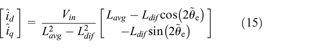
Based on the response current on the estimated d-q axis obtained from the pulse signal in (15), further processing yields the following signal:


In the subsequent rotor position tracking process, drawing inspiration from the MPC, a novel calculation module is introduced, which is based on IPS and utilizes the designed cost function.
To facilitate implementation in a digital controller, (16) and (17) can be rewritten in a discrete form as follows:


where

The specific comparison between the conventional current signal and the modulated current signal can be seen in Figure 6. After a rough rotor polarity identification, the rotor position error can be minimized to (−π/2, π/2). From the figure below, it can be seen that conventional current signals containing rotor position information exhibit multiple convergence points within the value range. In addition to correct convergence, when there are estimation errors in the rotor position, denoted as ±π/2, the value function will converge, resulting in a tracking error of the rotor position (i.e. convergence to the triangular point). To ensure the correctness and uniqueness of convergence in the processing of conventional current signals, it is necessary to further narrow down the value range, which increases processor computation, and complexity. However, by comparing it with the conventional signal within the specified value range, it is evident that the processed signal not only achieves accurate rotor position tracking (i.e. convergence to the circular point) but also guarantees the correctness of convergence.

Comparison diagram of signal. (a) Conventional current signal. (b) Modulated current signal.
Furthermore, based on the obtained modulated current signal, a cost function can be designed as follows:

where

where
Under the premise of meeting the convergence conditions of the iteration, multiple operations can lead to an approximate solution that makes the cost function equal to zero. This approximate solution represents the optimal rotor position within the allowable error range.
Based on the above principles, an IPS-based calculation module can be constructed. The calculation module obtains different response currents by injecting pulse signals at different phases and reconstructs the cost function. Subsequently, through iterative design methods, better rotor positions are continuously obtained based on existing results. When the number of iterations or the corresponding cost function reaches the preset threshold, the estimated phase can be output to estimate the rotor position.
Analysis and specific implementation of iterative algorithm
After rough polarity identification, the implementation of the proposed calculation module is divided into three modules: initialization of iterations, iteration of the Secant method, and output of the optimal rotor position. Additionally, considering the superiority of the interpolation iteration over the extrapolation iteration in practical applications, the interpolation method is used in the design to make the convergence faster.
The flowchart of the iteration process for the proposed calculation module is shown in Figure 7.

Flowchart of the iteration strategy for the proposed calculation module.
To demonstrate the superiority of the Secant method over the four-stage search algorithm in Ref. 45 in terms of convergence speed, a series of theoretical iteration results and errors are obtained using the proposed iteration strategy. The iterative results are presented in Table 1.
Iterative results of the proposed iteration strategy.

From the table presented above, it can be seen that after the initial two fundamental operations and three iterations, the rotor position error can be reduced to below the level of 10−3 rad.
The proposed pulse injection method requires only a few discrete pulse signal injections to achieve high-precision control accuracy, avoiding motor rotation caused by multiple or long-term pulse signal injections. The discrete position angle scheme avoids the inherent defect of the traditional PI controller’s sensitivity to motor parameters by directly quantifying the rotor position information. Moreover, when compared to the method in Ref., 45 the proposed iteration strategy demonstrates notable advantages in terms of computational efficiency and convergence speed.
Convergence verification of secant method
As shown in Figure 8, The sufficient conditions for the convergence of the Secant method shown in (22) within the interval of (–π/2, π/2) can be summarized as follows:
1) The first derivative of j(k,i) is not zero when there is no error in estimating the position of the rotor.
2) The second-order derivative of j(k,i) exists and is continuous in a neighborhood near the zero point of convergence.
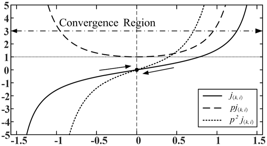
The curves of
To verify the convergence of the Secant method in iteration within the interval of the rotor position in the proposed calculation module, the first and second derivatives of the equivalent cost function are calculated as follows:

The cost function and its first and second derivative curves constructed in this paper and the Secant method are satisfied. Therefore, the method can theoretically obtain the optimal estimated rotor position within the error range by iteration.
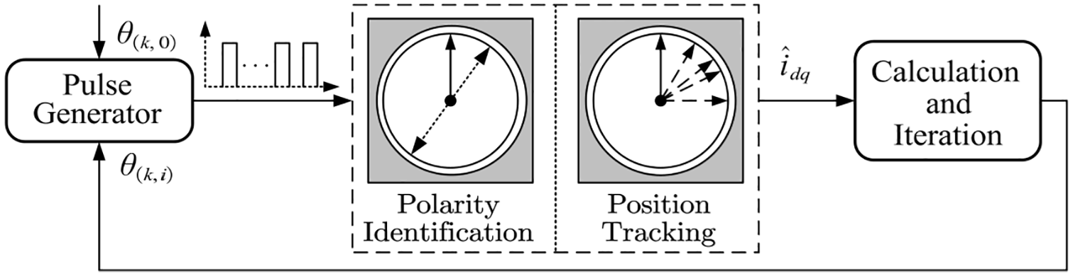
Unification of rotor position detection and polarity identification
By combining Part B and Part C in Section III, the proposed motor initial position detection scheme based on pulse signal injection can be formulated. The implementation steps of this scheme can be divided into two parts: the polarity identification module and the rotor position tracking module. The two parts have discrete characteristics and can be implemented as a whole.
The proposed scheme is implemented in a closed-loop system of pulse current injection position. To validate the proposed scheme, a specific overall control system diagram was designed based on the existing PMSM. Figure 9 illustrates the overall control block diagram for PMSMs based on field-oriented control.

The overall control block diagram of the proposed sensorless control scheme for PMSMs.
Simulation validation
To verify the effectiveness of the proposed scheme, a simulation model based on Simulink was established. A controllable three-phase voltage source with snubber resistors is used to achieve the injection of pulse signals. To ensure that there is no interference between continuously injected signals, the pulse width and interval of the injected signals are configured to be 100 and 500 μs, respectively. The PWM switch frequency is set to 20 kHz, and the saturation characteristics of the d-axis magnetic circuit are simulated by adding a new linear term to Ld.
Validation of the proposed scheme when rotor position is preset
When the position of the rotor is preset to 40°, during the entire rotor position tracking stage, through an iterative process, the position of the injected signal, and the error between it and the preset position under pulse signal injection are shown in Figure 10. From the figure, it can be seen that the rotor position obtained by the proposed scheme converges to the preset position after five pulse signal injection. Due to the advantages of the selected iterative method, under the same number of pulses injected, the accuracy of the entire process is also much higher than other schemes previously mentioned.

Simulation results when the rotor position is preset to 40°. (a) The phase of the injected pulse signal. (b) Position error of injected pulse signal.
Validation of the proposed scheme in multiple rotor positions
Figure 11 presents the estimation errors and the estimated positions attained by the proposed scheme after the injection of five pulse signals when the rotor is set to multiple positions. In Figure 11(a), the capability of the proposed scheme to achieve high-precision and error-free estimation of position is demonstrated. Additionally, as can be observed in Figure 11(b), the estimation error is confined within the ±1.5 ×10⁻³ rad.

Simulation results at different preset positions. (a) Estimated position. (b) Estimated position error.
Experimental validation
To assess the effectiveness of the proposed initial position determination scheme utilizing pulse sequence injection, a comprehensive set of experiments is being conducted, and a comparative analysis is being performed against the conventional approach employing HF square wave injection.
In this experiment, the TMS320F28335 digital signal processor is harnessed for the execution of the control algorithm, coded in the C language through Code Composer Studio. The experimental data are being acquired and plotted on a PC using MATLAB. The experimental setup involves the PMSM platform, where the sensorless control system diagram, as depicted in Figure 9, is being utilized. The experimental equipment includes torque sensors, a PMSM, and a magnetic powder brake, which are necessary for motor control. The configuration of the experimental platform and equipment is detailed in Figure 12, and the main parameters of the motor used in the experiment are shown in Table 2.
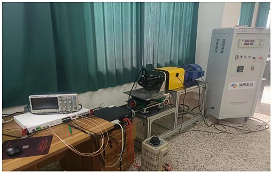
Experimental platform and equipment composition.
Main parameters of drive system.

Comparison of initial position determination
To perform a specific analysis and comparison of the performance of the proposed rotor initial position detection scheme, we preset the initial rotor position at 40°. In this comparison, we selected the widely used initial position detection scheme based on HF square wave signal injection as the reference and contrasted it with the proposed iterative initial position detection scheme based on unipolar pulse signal injection. The detailed experimental results are presented in Figure 13.

Experimental results of initial position detection. (a) Conventional square wave signal injection scheme. (b) Proposed scheme.
In the above figure, states 1, 2, and 3 represent the free state, rotor position tracking state, and polarity identification state, respectively. From Figure 13(a), it is evident that the conventional square wave signal injection scheme requires a longer duration in the rotor position tracking state. Moreover, after completing the estimation, it necessitates the additional step of identifying the polarity of the rotor. Moving on to Figure 13(b), it can be observed that the proposed scheme based on pulse signal injection streamlines the process by combining polarity identification with rotor position tracking, resulting in less time consumed throughout the entire procedure. From the obtained rotor position estimation results, it can also be found that the proposed scheme converges faster. When the rotor position is preset to 40°, the proposed scheme can accurately track the rotor position after a limited number of iterations in the experiment.
It should be noted that the proposed scheme can further reduce the estimation time at the expense of a certain reduction in accuracy. Specifically, under the experimental conditions, when the initial position of the rotor is preset to 40°, after polarity identification, an estimated rotor position with an error of approximately −0.05 rad can be obtained after only one pulse injection (subsequent pulse signals are no longer injected, and the estimated result corresponds to the green line), depending on the required accuracy. Thanks to this, the running time and computational burden of the control system are reduced, and additional adjustability is provided.
In order to demonstrate that the proposed scheme has better rotor position error and calculation rate, the proposed scheme is compared with the binary search method in Ref., 10 with the preset position being π/7. Table 3 compares the number of iterations and rotor errors of the two schemes. It took 15 iterations for the binary method to obtain rotor error accuracy similar to that of the secant method.
Comparison results between the binary method and the secant method.

Verification of motor startup with proposed scheme
In sensorless control, improving the starting performance of the target motor relies on accurately estimating the initial position of the rotor. In this section, we employ a conventional low-speed sensorless scheme to validate the performance of the SPMSM startup process.
Notably, the initial rotor position detection scheme proposed in this paper is only utilized during the startup phase. In the experiment, the rotor position of the motor is manually set at 40° to verify the effectiveness of the proposed scheme in tracking the initial position of the rotor.
As depicted in Figure 14, it is evident that the proposed scheme accurately tracks the rotor position at standstill and effectively leverages this information for low-speed start-up.

Startup with initial position detection scheme. (a) Rotor position. (b) Speed.
Conclusion
In this paper, a method is presented for determining the initial position of the motor rotor through the injection of unipolar pulse sequences. Compared with the conventional method of HF signal injection, the proposed scheme integrates both polarity identification and rotor position tracking. This scheme is achieved with just five pulse signal injections, resulting in the completion of the entire process and the reduction of error to less than 10−3 rad. The iterative method in this scheme contributes to the economization of cost both in computation and time throughout the implementation. Moreover, this scheme can operate independently of external fixed PI parameters, conferring upon it a certain level of robustness and portability. This means that such methods based on discrete pulse injection can be used for various motors. To verify this viewpoint, an initial position detection method for three-phase PMSMs is designed. The results of simulation and experimental analysis based on an SPMSM have confirmed the superiority and compatibility of the proposed scheme.
Particularly noteworthy is the proposed initial rotor position detection scheme, which can be applied not only to the SPMSM discussed in this paper but also to the IPMSM. In addition, the complexity of this scheme can be further adapted by modifying the number of injected pulses to match the desired accuracy, thereby correspondingly curtailing execution time. This adaptability is of great significance for practical applications.
Footnotes
Handling Editor: Divyam Semwal
Funding
The author(s) received no financial support for the research, authorship, and/or publication of this article.
Declaration of conflicting interests
The author(s) declared no potential conflicts of interest with respect to the research, authorship, and/or publication of this article.