
Abstract
This article presents the bolt self-loosening mechanism in curvic coupling due to the structural ratcheting under cyclic loading. Finite element simulations are carried out under several loading conditions with different preloads and cyclic torque loadings on curvic coupling. To avoid relative rotation between bolt and nut in simulation, the surface between the threads of bolt and nut are connected together. The finite element analysis results reveal that the local cyclic plasticity occurring near the roots of the engaged threads resulted in cyclic strain ratcheting. The structural ratcheting causes the gradual loss of clamping force with loading cycles in bolts and the stresses to redistribute in the curvic coupling. Either the structural ratcheting behavior or the fatigue strength of the curvic coupling is more sensitive to the magnitude of the torque load in contrast to the magnitude of the preload of the bolt. Comparatively, the large preload of the bolt or the low magnitude of the torque load is benefit for improving the structural integrity in curvic coupling under the bolt self-loosening.
Introduction
Curvic couplings are widely used in large power equipments, such as aero-engine and heavy-duty gas turbine. Owing to the special feature of the curvic teeth shape, the curvic couplings have lots of advantages, such as reliable positioning, precise centering, excellent structure stability, strong loading, and bearing ability, meeting the requirements of strength, vibration, and fatigue life. Meanwhile, the centering ability can be improved by repeated preload and running-in. Therefore, it is being used more and more widely. Because of the complex shape of the curvic teeth, the stress distributions and part stiffness in curvic coupling are difficult to be studied in theory. Therefore, only a few research works have been studied by researchers. Pisani and Rencis 1 compared the finite and boundary element methods to analyze the nominal hoop stress with the corresponding stress concentration factor with a single-tooth non-contact model in simple two and three dimensions. In order to analyze the rotor character in dynamics, NL Pedersen and P Pedersen 2 did some works to determine the equivalent flexural stiffness of a curvic coupling. Richardson et al. 3 carried out a photoelastic experimental technique to validate the three-dimensional (3D) finite element analysis results in the curvic coupling. The bolt stress of the curvic coupling under the conditions of a blade release in the 3D finite element model was analyzed by Richardson et al. 4 for the improvement of the curvic coupling design. Similar work had been done by Jiang et al. 5 with considering the case of a blade release in a 3D finite element model of a heavy-duty gas turbine. The stress distributions and contact behavior of the curvic couplings of a heavy-duty gas turbine with a spindle-bolted rotor were analyzed by Yuan et al. 6 by finite element analyses with the 3D model during the load cases of preload, warm up, speed up, and running of the rotor. Experiments and finite element simulations were conducted by some researchers7–9 to reveal the structural behavior of the curvic coupling.
The stress and strain distribution state of the preload spindle bolts of curvic couplings is very important for its structural integrity. However, the preload loss case of bolt in curvic coupling is never mentioned in the researches above. The gradual loss of bolt preload in curvic coupling would contribute to bolt self-loosening. It can result in a decrease in the structural stiffness or the separation of curvic coupling and lead to the joint failure. Such failure would do harm to the structural integrity of curvic coupling and result in higher maintenance expense, costly downtime, and can be catastrophic in rotor.
Up to now, many researchers have made a lot of efforts to make clear of the bolt self-loosening.10–26 Owing to the complex profile in thread geometry, it is very difficult to observe the local deformation and possible minor slip. Therefore, the mechanism about the minor deformation of thread should be explored by conducting the self-loosening experiment of the bolt. Simultaneously, the revelation of that mechanism should be done by means of theory and simulation analyses. It was found in experiments that the nut begins to back off only when the preload of the bolt was small enough below a certain critical value. Then, the self-loosening level of the bolt preload will exceed that value rapidly.
The experiments illustrated that the bolt self-loosening could be shown in two separate phases. 10 In the first phase, it was observed that there was no relative rotation between the bolt and nut. The bolt self-loosening was caused due to the plasticity accumulation or ratcheting of the materials in thread root. Another phase meant that the relative rotation between the bolt and nut, which lead to the obvious backing off of the nut and the preload, decreased rapidly. There may exist a superposition mode that occurs at the transfer moment between the forms of the aforementioned two phases. The first phase of bolt self-loosening was mainly studied by Jiang et al. 10 based on the finite element elastic–plastic analysis with ratcheting theory. Some researches established the 3D finite element model of the thread and focused on the research of the bolt self-loosening in second phase. Yamamoto and Kasei 11 developed a two-phase theory, in which a quantitative model was proposed about the nut sliding along the thread of bolt under external load and preload in bolted joint. However, there was no experiment to verify their research.
Sakai 12 tried to explain the requirement of bolt self-loosening due to the self-rotation of the nut. It was found by Sakai 13 that the nut would not rotate unless the contact surface friction of the thread was very small. Zadoks and Yu14,15 thought that the bolt self-loosening would be inevitable after conducting a serious of experiments about the bolt self-loosening in bolted joint subjected to transverse load and found that there was a critical force for bolt self-loosening. It was found by Zadoks and Kokatam, 16 in their further research, that the necessary condition for the bolt self-loosening was the sliding between the contact surfaces of the threads and between the contact surfaces of the nut and member. Jiang et al. 17 studied the self-loosening behavior of the shape memory alloy (SMA) bolt due to the phase transformation ratcheting of SMA materials.
The friction force between those surfaces should be overcome if the rotation of the nut were to happen. The impact load was considered as the only phenomenon which would cause simultaneous slip on the surfaces of threads and bolt head. The analysis result was verified by experiment.
However, both simulation and experiment in those researches were conducted in very low preload of the bolt as compared to those used in the real applications. The transverse or shearing loading (perpendicular to the fastener axis) was the most severe form of loading for vibration-induced loosening according to the analysis results by Junker 18 in the 1960s. It was found that the gross slip at the head and thread interfaces was the cause of the bolt loosening. Several studies had been performed to model the loosening of fasteners19–22 subjected to dynamic shear loading and had contributed to the understanding of loosening. Pai and Hess19,20 illuminated the various causes of slip under shear loading and further revealed that there were mainly four possible processes of loosening characterized by gross and localized slip in the bolt joint. The investigation of the self-loosening mechanism of the bolt was carried out by Shoji and Toshiyuki23,24 due to lateral load and impact. It was found that the bolt loosening was caused by the thread shape, that is, the wedge being inclined to the bolt axis. Qin et al. 25 proposed an analytical model for the bending stiffness of the bolted disk–drum joints and found that the bolted disk–drum joint lead to a decrease in the rotor critical speeds due to the softening of the joint stiffness. Further research by Qin et al. 26 analyzed the influence of the bolt loosening on the rotor dynamics system with the similar rotor structure of the bolted disk–drum joint in their previous study. 25 Nassar and Yang27,28 proposed a new mathematical model for the contact friction torques and the shear forces under transverse excitation to study the effect of different thread parameters on the self-loosening phenomenon in threaded fasteners. It was found that the higher bearing, thread friction coefficients, and a lower ratio non-dimensional value could minimize the potential of vibration-induced loosening, bolts that are subjected to a higher vibration amplitude.
Fatigue and self-loosening were found as two failure modes in bolted joints. 10 Fatigue could be thought as a major failure form as a bolted joint was subjected to tensile load and self-loosening was often found in a bolted joint subjected to transverse or shear load. Embedment may be a factor that causes the clamping force reduction in this research. Embedment refers to the removal of the high spots and indentation in the contact areas. As to medium carbon steel, it had been verified that embedment is not a significant factor influencing the self-loosening behavior of the bolt due to ratcheting. 10 Creep of the materials can cause the reduction in clamping force of bolt. 28
Self-loosening is the gradual loss of the clamping force by the role of cyclic external loading in the bolted connections, especially shear loading. The bearing loads of curvic coupling are usually torque load and centrifugal load. These loads would turn to shear load, playing a role in the contact surface of bolt head and disk in curvic coupling.
Therefore, the self-loosening rule of the spindle bolts of the curvic coupling and its causes are mainly studied in this article. In this research, a 3D elastic–plastic finite element model as well as self-loosening experiments is built to study the cyclic plastic deformation involved in first stage of self-loosening. The redistribution of the stress and strain in curvic coupling due to bolt self-loosening under cyclic loading, caused by the cyclic plasticity accumulation at thread root, is analyzed and focused on the cases of different preloads and different torque loads on disks.
Self-loosening experiment of bolts in curvic coupling
Experimental procedure
The bolt self-loosening experiment is conducted using a custom-designed testing machine, as shown in Figure 1. The experimental setup consists of curvic coupling, bottom base plate, foundation bed, twisting plate, and wire rope. The curvic coupling consisted of six bolts and two disks. There are 24 curvics in each of the disks. A torque load should be applied on one disk to loosen the bolts in curvic coupling, and another disk should be fixed at the bottom base plate. The details about the experimental procedure are shown in Figure 2. The wire rope connected to the loading nut and bolt as the loading device is to apply the torque load on the curvic coupling to actuate the rotation of the twisting plate. The bending moment would be generated in the curvic coupling along the axis of disk that would lead to the bolt loosening in curvic coupling. If the tightening load made by the loading bolt is asymmetrical or not synchronized, then that bending moment would be produced. Therefore, in order to ensure the symmetry of deformation along the axis of disk in torque loading, two dial indicators are placed at the each end of the twisting plate. The dial indicators can guarantee whether the same step in loading process is for the movement of two ends of twisting plate. The range of the dial indicator is 10 mm. By this way, the relative twisting angle between the two disks of curvic coupling can be controlled and detected within the scope of 5 .

Mechanical connection diagram of the experimental setup: (a) main view, (b) top view, and (c) schematic diagram for loading and test process.
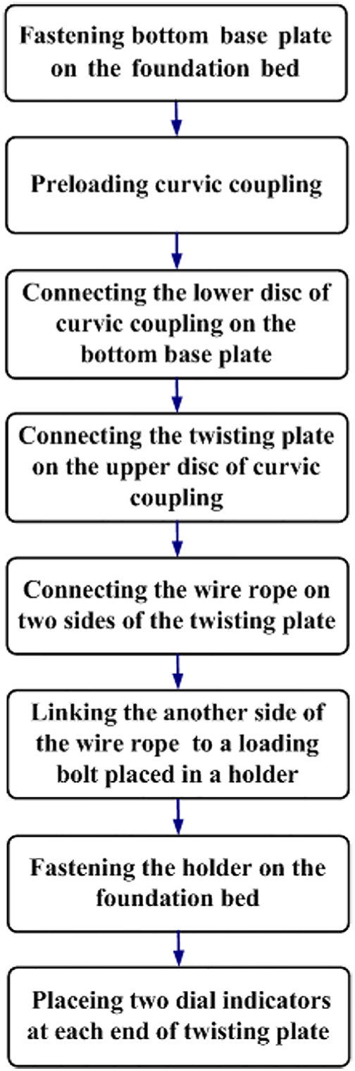
Experimental procedure.
The skeleton of a curvic is very complex, therefore, a lot of parameters need to be defined to describe the curvic geometry including addendum height

Tooth section in axial direction.
List of curvic sizes and related dimensions.


Model geometry.
The experimental condition is at room temperature. The experimental devices include the strain-testing instrument MX100 and a dual-core computer for the storage of the strain datum. The clamping force is tested by strain gauges affixed on the bolt bar surface along the axial direction of the bolt. The strain data could be obtained by strain gauge sensor through strain-testing instrument MX100. Because the accuracy in quality of the strain data is significantly influenced by the temperature, temperature compensation is necessary to be used in the experiment to get more precise data. A strain gauge for collecting the strain data and another strain gauge that need not collect the strain data are connected together to the strain-testing instrument by the half-bridge method. The strain gauge that need not collect the strain data should be affixed on the metal surface with the same temperature field and material as the bolts in the curvic coupling. By this way, the temperature compensation technique can be realized.
The testing frequency of the strain-testing instrument is 1 Hz. One bolt is attached by one strain gauge along the axial direction of bolt, as shown in Figure 1(c). It is obvious that the curvic coupling could be divided into six parts, each part in bearing load corresponding to one bolt is symmetric when the torque load is applied. So, the testing result from only one bolt strain data can satisfy the requirement of the experiment. However, in order to get more precise and reliable testing results, there are four strain-testing data to be taken at the same time in these experiments.
The self-loosening process of a bolted joint consists of two distinct stages. The first stage of self-loosening is due to the ratcheting deformation of the materials at the thread of bolt. The second stage of self-loosening is characterized by the back-off rotation of the nut. 10 This work is concentrated on the first stage of self-loosening of the bolt. However, the rotation between the bolt and the nut may happen if the bolt and the nut are not fixed with each other, which will lead to the bolt self-loosening. In order to ensure no rotation between the bolt and the nut, a strong thread locker, superglue 262, made in China, is used to glue the nut to the bolt in experiments. This adhesive is generally used for heavy shock and vibration applications. The use of the thread locker would restrict the shear movement of contact surfaces of threads that has no influence on the normal contact stress distribution, which would ensure no backing off of the nut can occur during the self-loosening experiments.
Experimental results
There are two sets of experiments to be conducted with different preload of the bolt by 5.55 and 8.98 kN, respectively. The torque load is controlled by the rotation of loading nut with the torsion displacement 0.7° on the twisting plate. A full one cycle of transverse torque loading includes two steps: loading in positive direction to its maximum from zero position and unloading to zero, as shown in Figure 5. The loading frequency can be kept at low level due to the time-independent character of 1045 steel materials at room temperature. All contact surfaces have no lubricants. The appropriate level of preload should be applied on the bolts. In this research, the preloads are 5.55 or 8.98 kN, which corresponds to the axial stress equal to 40%∼80% of the nominal yield strength of the bolt materials 582 MPa.

Loading steps.
Tables 2 and 3 show the tested strain value reduction (in mm/mm) that reflect the clamping force reduction with the number of the torque loading cycles. In the tables, P0 denotes preload. The mean value, standard deviation, coefficient of variation (COV) values, and the confidence interval of the 10 sets of specimens are calculated to analyze the variation trend and reliability of the specimens. The initial several torque loading cycles result in the most significant reduction in clamping force. The rate of loosening in clamping force decreases with the increasing number of loading cycles. For the controlled torsional angle experiments, the self-loosening is a gradual process. The larger preload would produce more severe self-loosening rate of the bolt. In these experiments, the decreasing of tested strain is in the range of 10–15 after 40 repeated transverse torque loading cycles.
List of test specimens and statistical results for P0 = 5.55 kN case.

COV: coefficient of variation.
List of test specimens and statistical results for P0 = 8.98 kN case.
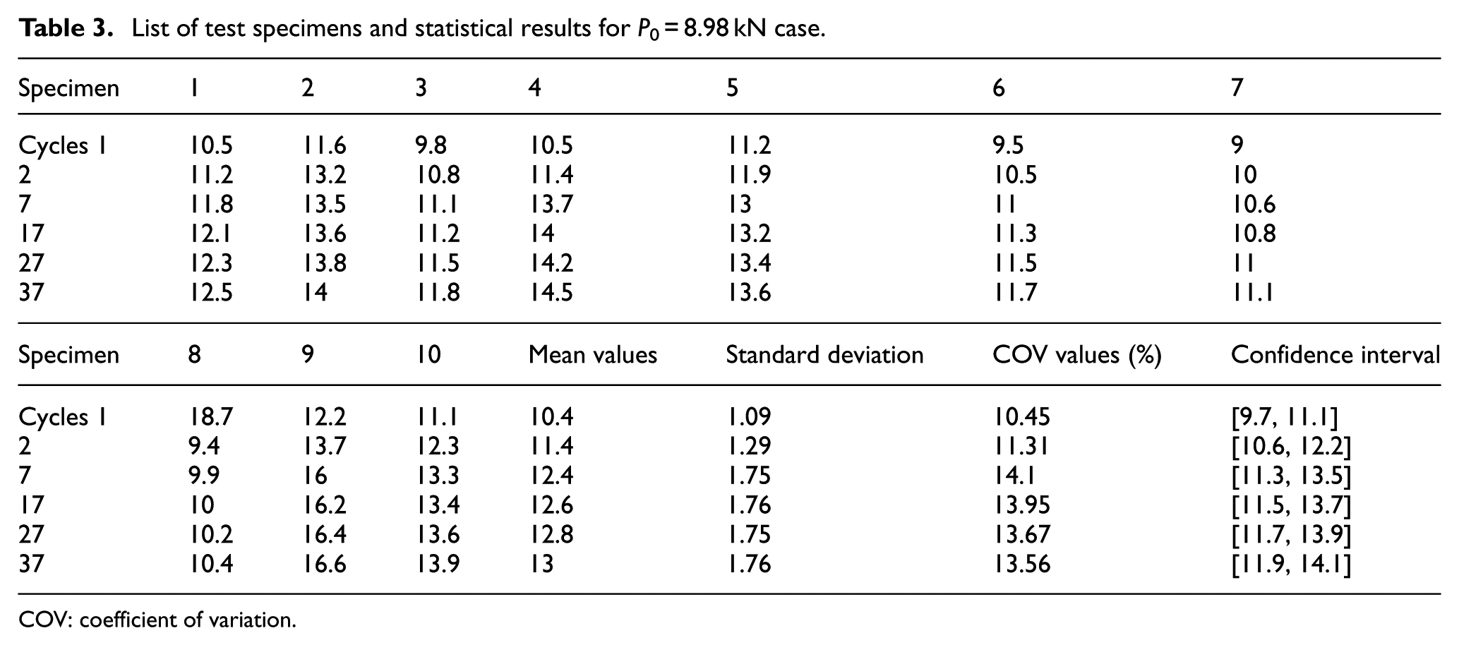
COV: coefficient of variation.
Finite element simulations
3D finite element model
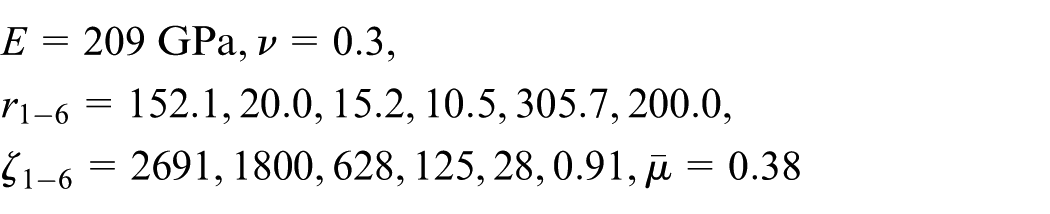
A 3D finite element model is created using the software package ANSYS. 29 The solid element 185 is picked in this analysis due to its ability of elastic–plastic analysis. The material in modeling is isotropic. Young’s modulus is 209 GPa, and Poisson’s ratio is 0.3. It is possible to construct finite element models of the bolt and nut in curvic coupling with high accuracy and computation efficiency. The whole finite element model is established such that it would be able to satisfy the requirements for this research, as shown in Figure 6. There are a total of 42,243 nodes and 75,955 eight-node solid brick elements in the mesh model. The type of the finite element analysis should be set as nonlinear static analysis. A total of three pairs of contact couplings are used to simulate the contact surfaces. They are the contact surfaces between the nut and the disk, between curvics of two disks, and between the bolt head and the disk. In the definition of contact pairs for finite element analysis, the contact surfaces of the bolt and nut with finer meshes are assigned to be the target surface, and the contact surface of the disk with coarser mesh served as the master contact surface. The contact surfaces of curvics and threads in the nut and bolt could be assigned as the target surface or the master contact surface at will. The right side of the contact surface of curvic is defined as the bearing side to transmit the torque load.

Three-dimensional finite element mesh model.
The thread modeling method, with accurately constructed helical thread geometry, proposed by Fukuoka 30 can be cited in this research to create the thread model using the equations defining the thread cross section perpendicular to the bolt axis. The threads are created precisely according to the ISO standard for M6×1 metric screw threads. Four threads are created for the nut and used in the model for the bolt. Due to the significant computational time involved, the different mesh sizes should be considered in the different parts of the mesh model structure. The threads in the bolt and nut are the most important load bearing parts, and so these structures should be built with relatively denser mesh model. The curvic is also a small part in curvic coupling, and this part can be modeled with small mesh size. The other disk parts, including the cylinder part and the shaft, can be established with relatively larger mesh sizes.
According to the research conclusion by Jiang et al., 10 when the bolt is loaded in the axial direction, the von Mises stress, which is still below the yield strength, obtained at the first thread root with coarse mesh grid is lesser than 7% compared to the result by the fine mesh grid. However, the local deformation at the thread root would reach the plasticity as the preload of bolt arrives at the level designed in these analyses. The analysis result with coarse mesh grid shows lower stress compared to the result by the fine mesh grid, within 3%. From the mesh density in Figure 6, which could be considered to be a level much enough, the accuracy could be ensured for the finite element analysis in this article. Therefore, it can be concluded that the finite element analysis result with the present finite element model is not very sensitive to the mesh density, under the high preload and plastic deformation condition. The fine convergence capability for the finite element analysis of the bolt loosening had also been done in the research by Jiang et al. 10
To ensure the same working condition of the bolts in curvic coupling with experiments in simulation, the relative rotation between the bolt and nut must be fixed. Therefore, the corresponding surfaces between the threads of the bolt and nut should be connected together to avoid the relative rotation in simulation. Therefore, the corresponding nodes between these two surfaces are glued together by ANSYS Parametric Design Language (APDL) program. According to the work by Jiang et al., 22 the friction coefficient of curvic can be set as 0.2 and the friction coefficient for the contact between the bolt head and the disk can be taken as 0.3.
Plasticity model
A cyclic plasticity model developed by Abdel-Karim and colleagues,31,32 which is very popular in recent simulation for structural ratcheting due to its capability to describe the general cyclic structural behavior including ratcheting or cyclic strain hardening, is used in the finite element simulations for the bolt self-loosenings in curvic coupling. The basic mathematical equations with discretization form in the plasticity theory are listed as follows


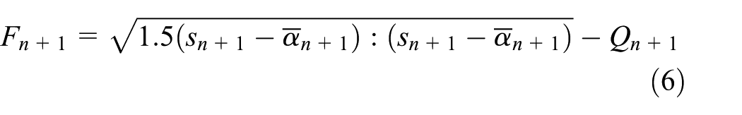
where
The Abdel-Karim–Ohno kinematic hardening rule is as follows
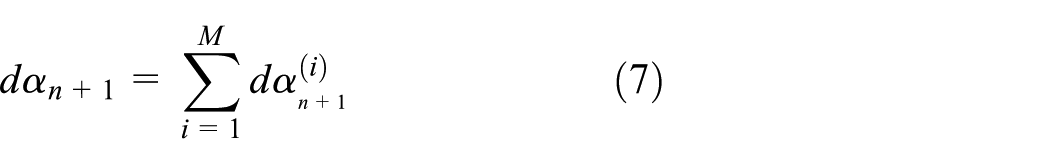
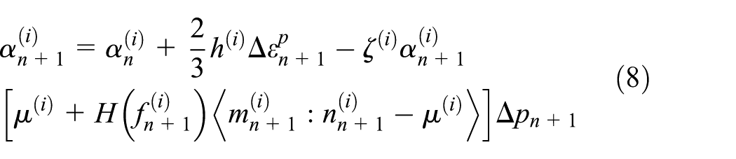


where
The plasticity model is implemented into the finite element package ANSYS 30 through the user-defined subroutine USERMAT. A backward Euler algorithm is used in an explicit stress update algorithm. The algorithm reduces the plasticity model into a nonlinear equation that can be solved by Newton’s method. The corresponding consistent tangent operator is derived for the global equilibrium iteration, which ensures the quadratic convergence of the successive iteration. Figure 7 shows the simulation diagram for self-loosening of the bolt in curvic coupling using the present plasticity model.
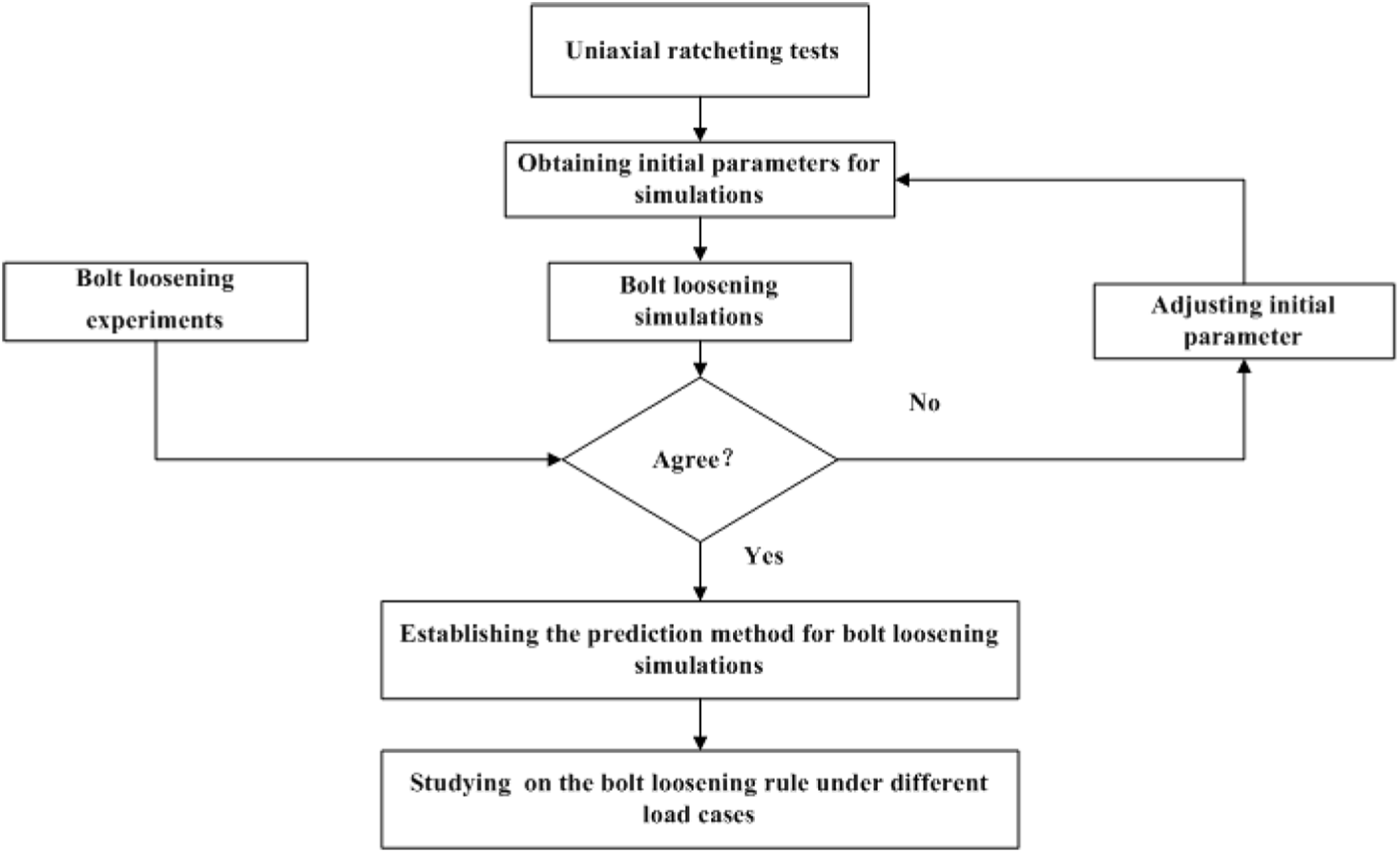
Simulation diagram for bolt self-loosening in curvic coupling.
The procedure for this simulation, shown in Figure 7, can be depicted as follows: First, the uniaxial ratcheting tests should be carried out for 1045 steel in MTS equipment to obtain the initial parameters about kinematic hardening model for the bolt loosening simulation. Second, the self-loosening experiments should be conducted based on a designed testing machine for bolt loosening in curvic coupling. Finally, it is necessary to create a 3D finite element model to simulate the bolt loosening in curvic coupling under different external loads. The used constitutive model for ratcheting has been depicted in the previous paragraph of this section. The initial parameters obtained from the uniaxial ratcheting test data are used for the bolt loosening simulation. However, it is to be noted that the initial parameters should be adjusted again to appropriately simulate the preload loosening of bolt by comparing it to the experimental result, and it means that
Since we have assumed the isotropy of elastic deformation and the additive decomposition of back stress, the problem of implicit integrating stress is reduced to solving a nonlinear scalar equation. The algorithm of successive substitution and its convergence to solve the nonlinear scalar equation had been studied by Kobayashi and Ohno. 33 More detailed formulation for the implementation of the plasticity theory into the finite element code can be found in Ohno and Wang.34,35 It should be noted that although the explicit integrating algorithm is of the computational efficiency without any iterative process and the convergence problem is naturally avoided, the implicit integrating algorithm with good accuracy and stability is more appropriate in this analysis, due to the requirement of the high-precision computation for analysis of the bolt self-loosening in curvic coupling.
Obtaining the initial parameters for bolt loosening simulation
In order to carry out the simulation for curvic coupling, the initial parameters about kinematic hardening model should be determined. Therefore, the uniaxial ratcheting tests have been conducted for 1045 steel under two different cyclic loads (i.e. 415 ± 415 and 440 ± 440 MPa). Actually, only one load condition for the uniaxial ratcheting test can satisfy the requirement to obtain the initial parameters. However, two different cyclic load cases can get those parameters more precisely. The material constants can be determined by the procedure described in the previous work.36,37 First, the parameters


where

The relationship between stress and plastic strain under uniaxial tension.
Second, a 3D eight-noded brick element is employed to simulate the test results for the unixal ratcheting. The experimental and calculated results are shown in Figure 9. It can be seen that the calculated results for uniaxial ratcheting strain curves are in good agreement with the experiments. The material parameters determined by uniaxial ratcheting experiments and simulations are used in the simulation for the bolt self-loosening in curvic coupling. Besides the bolt and nut in finite element model, other parts, such as curvics and disks, in curvic coupling could be considered as elastic.

Results of uniaxial ratcheting strain versus cyclic number at two kinds of load cases.
Finite element analysis results
Loading steps
The initial bolt preload and the cyclic torque load are consecutively applied to the finite element model. The shortening distance method between the nut and the bolt head could be applied to simulate the preload of bolt. 6 The preload of the bolt could be calculated by the sum of the axial node stress on the section of bolt. The torque load is applied in finite element model as shown in Figure 6. The torque load is applied at the nodes attached to the end surface of one disk in the circumference direction of the disk in the global cylindrical coordinate with rotating displacement. These nodes could be considered remote enough from the interest region of the critical parts such as curvics, bolts, and nuts. Therefore, the influence on the stress and strain analyses is very small with this method that it can be considered to be valid. The execution process of the torque load is the same as that in the experiment for the bolt self-loosening (Figure 2). It should be noted that the loading process is time independent due to the considered time independency for the 1045 steel materials at room temperature. The convergence can be guaranteed in the mesh size of this finite element analysis model in each step. The substep for the preload or torque loading step can be controlled within 10 substeps and is about 0.01° to 0.02° according to the magnitude of corresponding load.
Determination for
in controlling the bolt loosening
Figure 10 shows that the compared results of the experiments and the finite element analyses for the bolt preload change with the cyclic load progressing. It can be found from the calculated results that the bolt self-loosening by simulation is not ideal by comparing to the experiments as

Comparison of finite element predictions with experimental preload force reduction: (a) P0 = 5.55 kN and (b) P0 = 8.98 kN.
From the analyses results, it can be found that the simulations could be consistent with the experimental results. It should be illuminated that the convergence analysis about the self-loosening of a single bolt due to ratcheting had been done by Jiang et al. 10 with fine and coarse mesh model. In this article, the calculated correctness and the convergence about finite element analysis can be decided by two aspects. The first is the mesh quality and the mesh density. The convergence for the present finite element analysis has been proven the favorable mesh quality of the finite element model in previous sections. The node number for the whole finite element model in Jiang et al. 10 is 10,836 with 12 threads. However, the node number for the present model of threads is about 20,000 with just 4 threads. So, it can be considered that the mesh density in this article is larger and better than that in Jiang et al. 10
The second aspect is about the plasticity model with the implicit integration. The convergence of the finite element analysis with such plasticity model with implicit integration has been analyzed in “Plasticity model”. Therefore, the authors consider that the convergence with different element sizes for the present finite element model can be satisfied based on the two aspects mentioned above. To support the argument, the convergence analyses for different load step obtained from the current mesh model are compared with those obtained from using a coarser mesh model under P0 = 5.55 kN and Δθ = 0.7° load condition, as shown in Figure 11. The coarser mesh model has approximately two thirds of the number of elements of the current mesh model.

Comparison between two mesh models for self-loosening predictions.
It was found that under cycle torque loading, the von Mises equivalent stresses near the root of the first engaged thread obtained from the coarser mesh model can be 0.33% lesser than that obtained from the current mesh model. At the same location, the difference of the stress results obtained from the coarser mesh model was less than 0.19% than those from the current mesh model, as the significant local plastic deformation occurred. Therefore, it could be concluded that the stress and strain gradients near the geometry discontinuity that produce a high stress concentration in general decrease as plastic deformation occurs. Both the calculation by the coarser model and current model obtained close results to the experimental observations. The coarser mesh model provided a slightly lower reduction in preload force.
Bolt loosening under different load cases
Further simulations are carried out with the obtained parameters considering both different initial preloads and different torque loads. The initial preloads are selected as 5.55, 7.9, and 8.98 kN. The torque loads are selected as 0.1°, 0.2°, and 0.4°. The number of cyclic loading is more than 10 times the bolt preloading. The calculated results are shown in Figure 12. As compared to Figure 10, the same conclusion could be obtained. The decreasing rate of the bolt preload increases with the initial preload increasing of bolt; furthermore, it could be found that the decreasing rate of the preload of the bolt also increases with the torque load increasing on disk.

Observed preload force reduction with number of loading cycles in finite element simulations: (a) different preload and (b) different torque load amplitude.
The contours for the von Mises stress for the bolt from side face direction are shown in Figure 13. The preload is P0 = 8.98 kN. Figure 13 depicts the stress distribution after the preload is established in the bolt. It is noted that the stress distribution is helical along the thread root with respect to the bolt axis. The closer the distance between the thread and the clamed disk, the bigger the von Mises stress value. The maximum von Mises stress value is 688.87 MPa, and it occurs at the first engaged thread root. Plastic deformation can be observed near the thread roots due to the stress concentrations.

Von Mises stress contour after application of preload (unit: MPa).
Contact stress distribution of curvic surfaces during a torque loading cycle
Figure 14(a) shows the contact stress distribution on two contact surfaces of one curvic after the preload is established in the bolt. It can be found that the stress distribution is approximately symmetric on those two contact surfaces. The maximum contact stress is in the vicinity of the top of the contact surface curvic. However, the plastic deformation cannot be observed in these areas. After the torque load Δθ = 0.2° is applied to its maximum, the distribution of contact stress on two contact surfaces of one curvic is shown in Figure 14(b). This figure reveals that the right side in the curvic contact surfaces undertakes the torque load and the left side in those surfaces seems to be unloaded instead. Figure 14(c) shows the contact stress distribution on two contact surfaces of one curvic after the torque load is released to zero. A loading cycle is completed at this point. From Figure 14(c), it could be found that the bolt self-loosening seems to have no obvious influence on the stress distribution of curvic.

Contact stress in curvic during a torque loading cycle: (a) upon application of preload, (b) after reaching a maximum torque load, and (c) after the torque load returns to zero from maximum torque load.
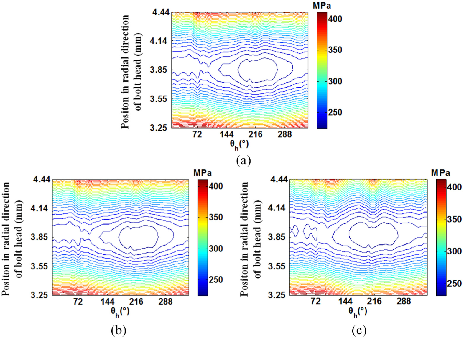
Von Mises stress distribution of curvic surface under different load cases
Figure 15 depicts the von Mises stress distribution on curvic surface with the cyclic loading progressing. It can be found that the maximum von Mises stress on curvic surface appears at the division point of contact surface of two contacting curvics and that one at the center point of contact surface of these two curvics is close to valley value. The stress at the top of curvic is at low level because that area does not need to bear contact load. From Figure 15, it could be found that the von Mises stress distributions on curvic surface (Figure 16) with the cyclic loading progressing are not obviously different as the preload of bolt is different, but those distributions present difference due to the different torque load. As the torque load is Δθ = 0.4°, the von Mises stress seems to be almost doubling. Compared to the von Mises stress distribution of curvic surface after preloading, there are obvious differences in the distribution after the first torque load is released to zero. It implies that the structural ratcheting behavior at thread has an influence on the stress distribution of curvic under some external load, especially the large torque load.

Von Mises stress in curvic with different applied load: (a) P0 = 5.55 kN, Δθ = 0.2°; (b) P0 = 7.9 kN, Δθ = 0.2°;(c) P0 = 8.98 kN, Δθ = 0.2°; (d) P0 = 7.9 kN, Δθ = 0.1°; and (e) P0 = 7.9 kN, Δθ = 0.4°.

Selected points on curvic surface.
Contact stress distribution of bolt head during a torque loading cycle
Figure 17 shows the contact stress distributions of bolt head at three different times during applied cyclic torque load. The preload is P0 = 7.9 kN, and the torque load is Δθ = 0.2°. It can be found that the contact surface of bolt head in the range of 0°–360°, shown in Figure 17, undertakes smaller contact load at the position close to the axis of disk and shows larger contact bearing at the position away from the axis of disk. In Figure 18, θh is the unfold angle of bolt head along circumferential direction. The stress at the division point of contact surface is the highest. The similar distribution in contact stress could be found on the contact surface of thread by the finite element analysis. From Figure 17(b), after the torque load is applied to its maximum, the contact stresses of curvic near θh = 90° and θh = 270° (Figure 18) appear to be decreasing. Because of the role of shear load on the contact surface of bolt head, due to the torque load on the disk, the contact surface is extruded to cause the surface deformation along the shear direction. Then, some positions such as the areas near θh = 90° and θh = 270° on the contact surface of bolt head are shrunk. So, these positions would decrease its bearing ability according to Hooke’s law, which would reduce the contact stress at these positions. After the torque load is released to zero, it could be found that the contact stress on bolt head contact surface in this time is not obviously different by comparing to the one after the preloading of bolt. The von Mises stress distributions at the middle diameter, which means that the diameter in the middle line of the external diameter and the internal diameter of the underhand surface of bolt head, of contact part between the bolt head and the disk are also analyzed in this article in the different cases of preload of bolt and torque load. Because the changing rules of surface deformation, due to the role of transverse shear load that causes the stress distribution change at the middle diameter of the underhand surface of bolt head, are similar to that on the curvic surface at the different loading point of the different external loads, it is not shown in this article. The von Mises stress at the middle diameter seems to be affected obviously as the torque load is Δθ = 0.4°, according to the analyses.
Contact stress of bolt head during a torque loading cycle: (a) upon application of preload, (b) after reaching a maximum torque load, and (c) after the torque load returns to zero from maximum torque load.

Unfold contact surface of bolt head along circumferential direction.
Stress and strain hysteresis loop at the first thread root
According to the finite element analyses, the biggest level to share the preload load on threads is undertaken by the first thread. So, the stress change at the first thread root is most obvious due to the cyclic plasticity. Figure 19 shows the hysteresis loop about the relationship between the von Mises stress at the first thread root and the rotation angle of the torque load. It can be found that the von Mises stress at the first thread root decreases with the cyclic loading progressing. The bigger the preload of the bolt, the larger the decreasing magnitude of stress. When the preload of bolt is fixed, the bigger torque load will lead to larger decreasing magnitude of stress. For example, as the preload of bolt is P0 = 8.98 kN, the von Mises stress at the first thread root reduces about 70 MPa at the end of first torque loading. As the preload of bolt is P0 = 7.9 kN, the von Mises stress reduces about 65 MPa. When P0 = 7.9 kN and Δθ = 0.1°, the von Mises stress reduces about 30 MPa. When P0 = 7.9 kN and Δθ = 0.4°, the von Mises stress reduces about 150 MPa. From the analysis results above, it can be concluded that the torque load plays a more obvious role of influencing the self-loosening behavior of the bolt in contrast to the preload role of the bolt. Further analyses show that the smaller preload of the bolt or the bigger torque load will contribute to the larger magnitude of stress in one cycle of torque load. As the preload of the bolt decreases 29.7%, the magnitude of the maximum stress at the threads increases by 3.8%. However, as the magnitude of the torque load increases by 29.7%, the stress increases by 62.3%. Therefore, it can be concluded that the self-loosening behavior of the bolt and the fatigue strength of the curvic coupling structure are more sensitive to the magnitude of the torque load in contrast to the magnitude of the preload of bolt.

Torque load versus von Mises stress response at the thread root: (a) P0 = 5.55 kN, Δθ = 0.2°; (b) P0 = 7.9 kN, Δθ = 0.2°; (c) P0 = 8.98 kN, Δθ = 0.2°; (d) P0 = 7.9 kN, Δθ = 0.1°; and (e) P0 = 7.9 kN, Δθ = 0.4°.
Conclusion
The current investigation is focused on the self-loosening behavior of the bolt under the guidance of the constitutive theory on ratcheting in curvic coupling without the backing off of the nut. The analysis results show that the constitutive model used in this article has the capability to simulate the self-loosening phenomenon of the bolt. The preload of the bolt and the magnitude of torque load have effects on the rate of the bolt self-loosening. It could be concluded that either the self-loosening behavior of the bolt or the fatigue strength of the curvic coupling structure is more sensitive to the magnitude of the torque load in contrast to the magnitude of the preload of the bolt. Both the experiments and the simulations about the bolt self-loosening are conducted with the guidance of the constitutive theory on ratcheting. Those theory models or experiments make contribution to explore the mechanism of bolt self-loosening at the initial stage in curvic coupling. However, the backing off of the nut, which had been verified as a potential effect factor on the bolt self-loosening, is not involved in this research and will be explored in future studies.
Footnotes
Handling Editor: Michal Kuciej
Declaration of conflicting interests
The author(s) declared no potential conflicts of interest with respect to the research, authorship, and/or publication of this article.
Funding
The author(s) disclosed receipt of the following financial support for the research, authorship, and/or publication of this article: The authors are grateful to the support of the National Natural Science Foundation of China (51775406, 51405371), 111 Project (B14042), the Equipment Pre-research Field Foundation of China (61402100202) and the Fundamental Research Funds for the Central Universities (JB180412).