
Abstract
A Stewart manipulator is used in the Five-hundred-meter Aperture Spherical radio Telescope to ensure the position and orientation accuracy of the feed receivers. Due to the weight limit, the feed cabin has a low stiffness, which highly affects the control accuracy of the Stewart manipulator based on the control conditions. The main purpose of this article is to present an effective accuracy design method of the Stewart manipulator of the Five-hundred-meter Aperture Spherical radio Telescope. First, error modeling of the Stewart manipulator with the structural deformation is set up, which can indicate the influence on the control error caused by the structural deformation in real-time control. Second, by analyzing the accuracy factors of the Stewart manipulator, the end-effector error limit caused by the structural deformation is obtained. Third, an error distribution method based on the maximum coefficient method is proposed, which guides the structural design of the feed cabin. Fourth, a semi-physical simulation model of the feed cabin is set up to simulate the control accuracy of the feed cabin, and the experiment results show that the control error of the feed cabin is within root mean square 4.8 mm. Finally, the feed cabin is effectively used in the Five-hundred-meter Aperture Spherical radio Telescope within its root mean square 10-mm accuracy requirement.
Introduction
The Five-hundred-meter Aperture Spherical radio Telescope (FAST), the largest single-dish radio telescope in the world, was built in Guizhou province, China.1–3
Figure 1 shows the design of the FAST. The radio telescope uses a feed support system to drive the feeds on its required position and orientation with high accuracy to receive radio waves. Therefore, a large-span six-cable-driven parallel robot is adopted to coarsely control the feeds.

FAST: (a) design of the feed support system of the FAST, (b) feed cabin, and (c) Stewart manipulator.
All the feeds are installed in the feed cabin. Figure 1(b) shows the feed cabin. The diameter of the feed cabin is about 13 m, and its weight is about 30 tons. In the feed cabin, an A-B rotator is used to control the orientation of the feeds with the six-cable-driven parallel robot. A Stewart manipulator is installed on the A-B rotator, which is shown in Figure 1(c). The Stewart manipulator is used to improve the position and orientation accuracy of the feeds. All the feeds are installed on the moving platform of the Stewart manipulator.4–6 The Stewart manipulator reduces and inhibits the influence of wind disturbance on the feeds and further improves the position accuracy of the feeds from 48 mm to root-mean-square (RMS) deviation 10 mm in real time, so as to achieve the astronomical observation accuracy requirement. Hence, the accuracy of the Stewart manipulator is vital for the FAST.
The Stewart manipulator has a typical parallel mechanism. Generally speaking, the accuracy of a parallel mechanism is divided into the static accuracy and the dynamic accuracy. The static errors are the errors caused by the manufacturing and assembly error, the hinge clearance, the steady-state load, the thermal deformation, and so on. Studies have shown that the static error is the main reason leading to end-effector error of the parallel mechanism, which accounts for more than 70% of the error,7,8 and the static error can be restrained during design and compensation.
So, this article mainly focuses on the static accuracy analysis and accuracy design of the Stewart manipulator, which improves the observation efficiency of the FAST. So far, great progress has been made in this field.9–12 In the past, it is generally considered that the stiffness of the Stewart manipulator is sufficiently high to be rigid. The structural deformation discussed in the past usually refers to the tolerance range of the mechanical components, which can be calibrated. However, the Stewart manipulator in the FAST has a peculiarity: low stiffness of structure due to the weight limit of the feed cabin.
Considering the safety of the feed support system, the weight limit of the feed cabin is 30 tons. Due to the complexity of the feed cabin and the weight limit, the structure of the feed cabin has lower stiffness, which will cause a larger structural deformation than common parallel mechanisms. Furthermore, the deformation value will change under different pose and dynamic situation. Thus, it is worthy of note that the structural deformation of the Stewart manipulator in this article refers, in particular, to the relative structural deformation in the full workspace under dynamic effects.
Furthermore, for the Stewart manipulator in the FAST, the position and orientation of the static platform cannot be directly measured. According to the control strategy of the feed support system, we can only obtain it by measuring the pose of the moving platform and the known structural parameters of the Stewart manipulator. The structural deformation during the control will apparently influence the control accuracy of the Stewart manipulator in real time. So, it is necessary to establish an error model based on structural deformation and other key factors.
Due to the 30-ton limit requirement, we cannot ensure that the whole feed cabin has a high stiffness. So, key parts of the feed cabin should be optimized for getting a higher stiffness. The key parts can be analyzed by accuracy analysis, and key parameters can be extracted. It is a useful method to ensure the control accuracy of the Stewart manipulator by distributing the structural error of the key parameters, and the result of the error distribution can guide the structural design of the feed cabin. According to the error model, this article first studies the error transfer coefficient which is related to the position and orientation of the Stewart manipulator in its whole required workspace. Second, this article researches the sensitivity distribution method based on maximum coefficient method of the Stewart manipulator.
For verifying the accuracy design results, a semi-physical simulation model of the feed cabin was built in a factory. The experiment results show the end-effector control accuracy of the Stewart manipulator is RMS 4.8 mm, which satisfies the accuracy requirement. Then, the feed cabin is effectively used in the FAST within its RMS 10-mm accuracy requirement.
In this article, description of the feed support system and the error modeling of the Stewart manipulator of the FAST are expressed in Section 2. Section 3 proposes the error distribution function and obtains the error distribution results based on maximum coefficient method. Finally, an experimental system is set up, and the terminal error of the Stewart manipulator is obtained.
Error modeling of the feed support system
Figure 2 shows the feed support system of the FAST. The position and orientation of the feeds are coarsely controlled by the six-cable-driven parallel manipulator and the A-B rotator. The workspace of the feeds, which is called the focal surface, is a spherical crown from about 140 m to 176 m above the active reflector. The Stewart manipulator fixed on the A-B rotator is to precisely control the feeds to RMS 10 mm. 4

Description of the feed support system.
Figure 3 shows the control strategy of the Stewart manipulator. 13 During control, forward kinematics is adopted to calculate the static platform’s position and orientation by the measured values of the moving platform and the driving legs and the calibrated structural parameters of the static platform. Then, according to inverse kinematics, the length of the driving leg is calculated, and the position control of the Stewart manipulator is carried out. Therefore, the structural deformation of the Stewart manipulator will affect the accuracy of the forward and inverse kinematics solution, thus affecting the accuracy of the position control of the Stewart manipulator. Therefore, error modeling of the Stewart manipulator based on the structural deformation should be set up.
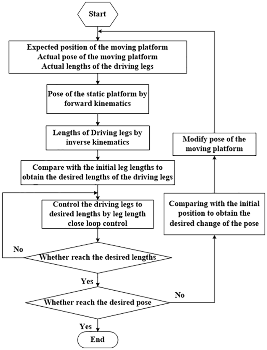
Control strategy of the Stewart manipulator.
Figure 4 is the Stewart manipulator in the FAST. There are two coordinate systems: a fixed frame

Geometric parameters of the Stewart manipulator.
The inverse kinematic equation of the Stewart manipulator is


where
As shown in Figure 4, assuming the structure is rigid, the vector method is used to set up an error model of the Stewart manipulator.

where

Substituting (equation 4) into (equation 3) yields

where

Therefore, the error transmission function for the Stewart manipulator is

where


According to control strategy, considering the structural deformation during the real-time control of the Stewart manipulator, the error caused by structural deformation can set up as follows:
When the structure is rigid, the lengths of the driving legs of the Stewart manipulator are

where
When the moving platform moves to the next point

So, the changes of the drive legs are

During the control period, the relative deformation of the

where

The structural deformation is related to tension of the six-cable-driven parallel manipulator and the pose of the feed cabin, and

Error distribution of the Stewart manipulator
The terminal accuracy requirement of the Stewart manipulator is RMS 10 mm. Three factors apparently affect the terminal accuracy of the Stewart manipulator: measurement error, control residual of the cable-driven parallel robot, and structural deformation. The effect of the three factors should be analyzed.
Error analysis of the measurement
According to Figure 3, the actual pose of the moving platform and the length of the driving legs can be measured in real time. The actual position and orientation of the moving platform is measured by total station, and the length of the driving legs is measured by encoders.
The influence of encoder error can be solved by (equation 6). Six total stations are used to measure the position and orientation of the moving platform, and its accuracy is improved using six location information. According to the research and test, the accuracy of the total station

where
Error analysis of the control residual of the cable-driven parallel robot
The purpose of the feed cabin is to reduce the residual error after the control of the cable-driven parallel robot and the A-B rotator so that the feed meets the RMS 10 mm precision requirement. The control error of the cable-driven parallel robot is caused by wind load, natural frequency of the supporting tower, the measurement, the controller design, and so on. The fluctuating wind load is the main factor that affects the control accuracy of the cable-driven parallel robot. Besides, the vibration of the feed cabin, caused by wind excitation and other external factors, affects the position and orientation of the Stewart manipulator.
The analysis found that the first-order natural frequency of the feed support system ranges from 0.14 to 0.18 Hz, which fits to the characteristics of large-scale cable-driven parallel robot. The low damping vibration mode has an important influence on the control stability of a large-scale driven parallel manipulator and can easily stimulate the resonance of the system.
Adopting the wind spectrum model (Davenport model), the control error of the cable-driven parallel robot can be obtained by loading the wind disturbance on the feed cabin, which is shown in Figure 5.

Error of the cable-driven parallel manipulator.
The Fourier transform of the residual control error of the cable-driven parallel manipulator is shown in Figure 6, which can show the cumulative error. As shown in Figure 6, by integral calculation, the maximum accumulative error of the cable-driven parallel robot within 1 Hz wind bandwidth is about RMS 19.8 mm. Therefore, in order to avoid the system resonance, the servo bandwidth of the Stewart manipulator will be less than the first natural frequency of the feed support system. So, the control bandwidth of the Stewart manipulator is set to 0.1 Hz. The error within 0.1 Hz wind bandwidth is about RMS 16.9 mm.

Cumulative error of the cable-driven parallel manipulator.
So, the residual control error of the Stewart manipulator

Error distribution of the Stewart manipulator based on maximum coefficient method
The accuracy requirement of the Stewart platform is 10 mm, it means

where

From (equation 14), the error transmission function for the Stewart manipulator can be obtained, and


where
The error transfer coefficient is related to the position and orientation of the Stewart manipulator. Therefore, the error transfer coefficient can be calculated in the required workspace. The parameters of the Stewart manipulator are listed in Table 1.
Main parameters of the Stewart manipulator.

In this way, we can get the error transfer coefficient in the whole workspace

The results shows that the error transfer coefficient is symmetrical for different error sources, and the maximum error transfer coefficient of the hinges and driving leg is the same, but the distribution is not the same in the workspace. Therefore, we define the error transfer coefficient of position as
Then, according to the maximum coefficient method

where
So, the error distribution based on maximum coefficient method of the Stewart manipulator can be expressed as
According to the distribution function, structure design can be optimized. After optimized design, the structural deformation at some typical pose can be studied such as Figure 7.
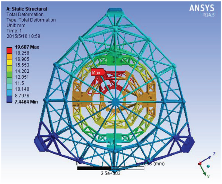
Structural deformation of the feed cabin in a given pose.
Based on the finite element analysis of the feed cabin, in the full workspace, under the cable-driven parallel manipulator and A-B rotator, the maximum relative structural deformation of the spherical hinge of the moving platform of the Stewart manipulator is about 2.6 mm, the maximum relative structural deformation of the spherical hinge of the static platform of the Stewart manipulator is about 1.7 mm, and the maximum relative structural deformation of the driving leg of the Stewart manipulator is about 1.4 mm.
Using the Monte Carlo and interval analysis method, 9,11,16–17 based on (equation 14), the terminal error of the Stewart manipulator in the full working space can be obtained as RMS 2.4 mm, which satisfied the distribution requirement.
Experimental result
The feed cabin is driven by a six-cable-driven parallel robot, so that the Stewart manipulator is used to compensate the residual error of the six-cable-driven parallel robot. The feed support system operates at more than 140 m above the reflector, so safety is the primary factor. Therefore, before performance debugging of the feed support system, it was necessary to do some functional debugging by stages. Besides, considering the weight and size of the feed support system, a semi-physical simulation model is adapted to debug the functions and performance of the feed cabin.
As shown in Figure 8, the semi-physical simulation model has three features:
The A-B rotator and Stewart manipulator are the real scale mechanisms which are used in the FAST.
For simulating the six-cable-driven parallel robot control error, we set up a dynamic simulation model of the feed support system. In the simulation model, we adopted Davenport model as the wind spectrum model. When loading the wind disturbance on the feed cabin, the simulation model simulates the control process of the six-cable-driven parallel robot and obtains the control error in real time.
We used six thread rulers as the measurement equipment and added some random measurement error to simulate the real measurement accuracy.

Experiment in the factory using semi-physical simulation model.
The experiment results are shown in Figure 9. The results show that the position error of the Stewart manipulator is RMS 4.8 mm.

Experiment result in the factory.
The main error is caused by wind disturbance in horizontal direction, and the error in the vertical direction is obviously reduced after being effectively controlled by the Stewart manipulator (Figure 9). The control accuracy satisfies the requirement. Meanwhile, no excitation by the Stewart control works on the cable-driven parallel manipulator.
Then, the feed cabin is installed on the cable-driven parallel manipulator in Guizhou, which is shown in Figure 10. After functional and performance debugging of the FAST, the control error of the Stewart manipulator in one trajectory is shown in Figure 11.

Experiment in observatory.

Experiment result in observatory.
According to Figure 11, the control error is RMS 4.6 mm. Similar to the experiment result, the main error is caused in horizontal direction, but the error in vertical direction is larger than the result in the factory which is caused by wind. Overall, more than 30 trajectories are tested, and all accuracy results are better than RMS 10 mm, which means the feed support system satisfies the accuracy requirement of the FAST.
Conclusion
This article addresses an effective accuracy modeling and distribution method of the Stewart manipulator in feed cabin of the FAST. First, considering the low stiffness of the feed cabin, error modeling with structural deformation based on the control strategy of the Stewart manipulator is set up. Second, measurement error and control residual of the six-cable-driven parallel robot are studied, so that the end-effector error caused by the structural deformation is calculated. Based on the error transfer matrix, error transfer coefficients are presented. Maximum coefficient method was adopted for the error distribution to reduce the negative influence of the structural deformation on the control accuracy of the Stewart manipulator. Error transfer coefficients of the hinges and driving legs are analyzed, and the structural deformation limit of the hinges and driving leg is 6.67 mm, which guides the structural design of the feed cabin. The experiment results on the semi-physical simulation model show that the control error of the feed cabin is RMS 4.8 mm. Finally, all trajectories’ control accuracy of the feed cabin in the FAST satisfies the RMS 10 mm accuracy requirement.
Footnotes
Handling Editor: Jose Ramon Serrano
Declaration of conflicting interests
The author(s) declared no potential conflicts of interest with respect to the research, authorship, and/or publication of this article.
Funding
The author(s) disclosed receipt of the following financial support for the research, authorship, and/or publication of this article: The study was financially supported by the National Natural Science Foundation of China (Grant No. 11203048), the Youth Innovation Promotion Association CAS, and the Open Project Program of the Key Laboratory of FAST, NAOC, Chinese Academy of Sciences.