
Abstract
The pressure pulsation test in an axial flow pump with and without the floor-attached vortex was performed. Pressure sensors were mounted on the impeller inlet section and impeller outlet section and guide vane section outlet of the axial flow pump. The investigations showed that the pressure pulsation in the axial flow pump was mainly affected by the impeller rotation. The time-domain characteristic curves of the pressure pulsation at the impeller inlet and outlet changed the most at different periods when the floor-attached vortex appeared in the pump sump. There was no significant difference between the time-domain characteristic curves of the pressure pulsation with and without the floor-attached vortex at the guide vane outlet. The pressure pulsation induced by the floor-attached vortex was a low-frequency pulsation of 2.12 Hz, which fluctuates periodically with time in the form of a trigonometric function. The pressure pulsation amplitudes with the floor-attached vortex were larger than those without the floor-attached vortex. The floor-attached vortex mainly affected the pressure pulsation in the impeller and had less influence on the pressure pulsation at the guide vane outlet due to the rectifying effect of the guide vane.
Introduction
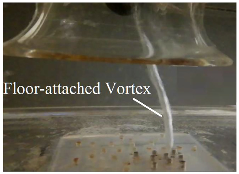
Inside an axial flow pump, the flow appears as a complex three-dimensional (3D) unsteady turbulent flow. The influence of pressure pulsation on an axial flow pump has always been the focus of attention. The inflow conditions determine whether the pump unit can operate safely. 1 FP Tang and LP Zhang 2 performed unsteady numerical simulations on the axial pump section and determined that the frequency of the pressure pulsation in the axial pump was mainly controlled by the impeller rotation frequency. WD Shi and HF Leng 3 carried out a 3D unsteady numerical simulation on the full flow field of an axial flow pump. It was found that the amplitude of pressure pulsation increases obviously when the flow rate deviates from the design point, the decrease in the number of guide leaves can increase the pressure pulsation at the guide vane outlet, and the number of guide vanes has no effect on the frequency of pressure pulsation. Tan et al. 4 conducted experimental measurements and numerical simulations of the pressure pulsation in a mixed-flow pump under different blade rotation angles and analyzed the influence of the blade rotation angle on the pressure pulsation and the vortex strength in the impeller. A new approach using anti-vortex methods as hydraulic-based anti-vortexes was investigated experimentally by T Ahmad et al. 5 In the investigated method, a submerged water jet was used as the anti-vortex mechanism, changing the intake-induced hydrodynamic pattern in the near-field of the intake structure, which could prevent the formation of undesirable intake vortices. C Liu et al. 6 used 3D-PIV (particle image velocimetry) to measure the floor-attached vortex under the flare tube of a vertical axial flow pump (Figure 1). By analyzing the detailed flow structure of the vortex core zone, the distribution regularity of circular velocity components in the vortex core was revealed, which was close to zero at the center of the vortex core and increased with an increase in the vortex core radius. T Chirag et al. 7 pointed out that high-amplitude pressure pulsations developed under off-design conditions, which caused moderate damage to the turbine components, and conducted pressure measurements on the turbine. The results showed that the frequencies at 50% and 70% of the load operating conditions were 0.22 and 0.24 with their harmonics, which was associated with the vortex rope because these frequencies are within the range of 0.2–0.3 times the runner speed. An experimental study of the 3D turbulent flow at a rectangular single-pump intake was conducted by M Ansar and T Nakato. 8 The test showed that the flow near the suction pipe was characterized by a longitudinal vortex whose strength increased in the stream-wise direction and a strong floor-attached vortex beneath the suction bell. To study the characteristics of low-frequency pressure pulsation of a tubular turbine, the unsteady internal flow field in a tubular turbine of a power station was numerically simulated by Y Zheng et al. 9 The results showed that there was a helical vortex rope in the draft tube that had the same direction as the runner hand of rotation. The frequency of the vortex rope in the draft tube was 0.22 Hz, and the frequency of the low-frequency pressure pulsation was mainly caused by the vortex rope.
Floor-attached vortex in the pump sump.
At present, research on the floor-attached vortex in the axial flow pump unit is more focused on studying its impact on the velocity field, and research on the impact of pressure pulsation is rare. However, the floor-attached vortex in the pump sump poses a great threat to the safe operation of the pump unit, so determining the relationship between the pressure pulsation and the floor-attached vortex can provide a great help for exploring the mechanism of the vortex occurrence.
Some work on the basic characteristics of the spatial and temporal evolution of the floor-attached vortex has been performed.10–11 The duration of the floor-attached vortex developed to form a vortex tube was approximately 0.96 s. The duration of the floor-attached vortex was approximately 3.8 s, and the interval was 3 min. The number of vortexes occurring was approximately five per minute, that is, the frequency of the floor-attached vortex occurring was approximately 0.12 Hz, and when the vortex appeared, the unit exhibited significant vibration and noise. 12 Based on existing research, this article conducted an in-depth study on the characteristics of pressure pulsation induced by the floor-attached vortex inside of the pump device.
Experimental setup
Axial flow pump unit
The energy performance test and the pressure pulsation model test were conducted on a vertical axial flow pump experiment stand. The experiment stand consists of an open-type pump sump, an EJA DMS5A-92DA pressure differential transmitter, a JCO MG10187 torque transducer, an ISW150-200A stainless steel centrifugal pump, a pressure-regulated cylindrical water tank, and a stainless steel soft-seal butterfly valve as shown in Figure 2. The impeller diameter is 120 mm, the hub diameter is 48 mm, the number of the impeller blades is 4, and the number of the guide vanes is 7. The pump sump is 840 mm × 360 mm × 300 mm. The distance of the flare tube mouth from the bottom of the pump sump is 92 mm. The length of the outlet pipe is 720 mm, and the rear wall distance is 200 mm. The purpose of this article is to study the pressure pulsation characteristics in an axial flow pump device under flow conditions with and without a floor-attached vortex. It is necessary to perform the pressure pulsation test under the flow conditions with the floor-attached vortex observed clearly. The floor-attached vortex occurs most obviously when the water depth of the pump sump is 300 mm. Therefore, the water depth of the pump sump is selected as 300 mm in this test scheme, and the impeller rotation speed is selected as 2200 r/min.
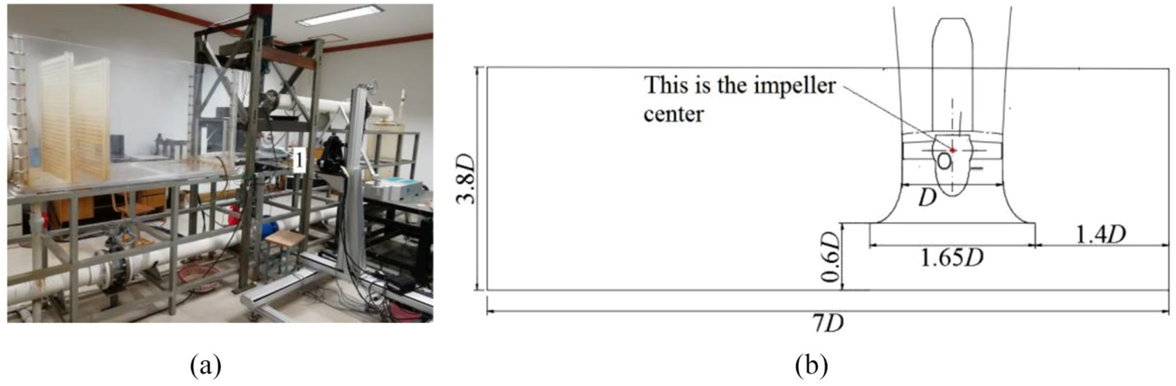
Pump model experimental setup: (a) axial flow pump test system and (b) geometry parameters of the axial flow pump 1: pump sump.
Pressure pulsation measuring points arrangement
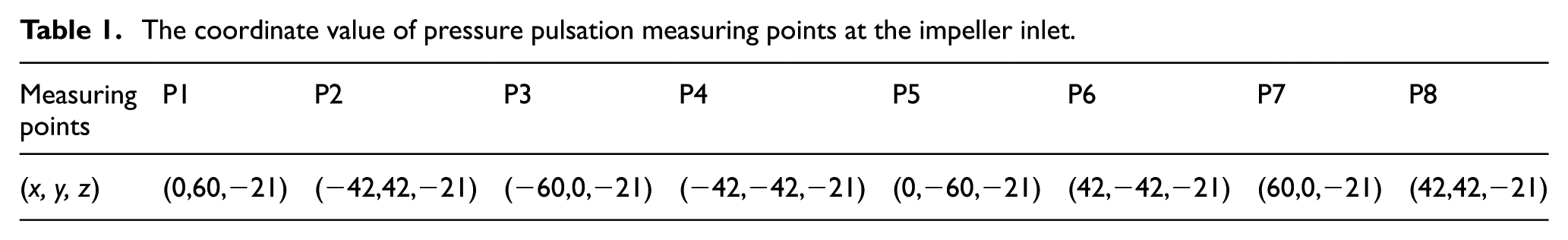
Pressure pulsation sensors (CY301 intelligent digital pressure sensor, Chengdu Test Company manufacturing) with high precision and stability were installed on section 1-1 at the impeller inlet of the axial pump, on section 2-2 at the impeller outlet, and on section 3-3 at the guide vane outlet. The specific locations of the pressure pulsation sensors are shown in Figure 3. The coordinate value of pressure pulsation measuring points at the impeller inlet and outlet and the guide vane outlet are shown in Tables 1–3, respectively. The center of impeller is the coordinate origin. The measuring range of each pressure sensor was 0–60 MPa with a test accuracy of 0.1%. The pressure pulsation sensors were connected to the adapter through a converter, which was connected to the computer via a network line. The pressure test software used the smart sensor pressure test system with a sampling time range of 1 ms to 1 s.

Position of the pressure pulsation measuring points.
The coordinate value of pressure pulsation measuring points at the impeller inlet.
The coordinate value of pressure pulsation measuring points at the impeller outlet.

The coordinate value of pressure pulsation measuring points at the guide vane outlet.

Due to the changes in the test environment, there was zero drift in the acquisition equipment at no load. To ensure the accuracy of the experimental results, the zero-point values were collected before the test, and the reference zero-point values were determined during the collection process to eliminate the influence of the environmental changes on the results. To accurately measure the pressure change when the floor-attached vortex occurred in the context of the instability of the vortex, the sampling duration tm was set to 3 s, while the sampling interval time ts was set to 1 ms according to the duration of the floor-attached vortex in the experimental investigation. That is, the sampling frequency fs was 1000 Hz. To further explore the influence of the floor-attached vortex on the pressure pulsation in the pump unit, the pressure pulsation test under the large flow condition without the vortex was performed simultaneously.
Flow condition test
Because the large flow rate is conducive to the formation of floor-attached vortexes, it is necessary to obtain the energy performance curve for the pressure pulsation test. As shown in Figure 4, the design flow rate Qd of the pump unit was 32 L s−1. H is the head of the axial flow pump, Q is the flow rate, and η is the pump efficiency. The floor-attached vortex appeared easily when the flow rate was over 1.2Qd, so the pressure pulsation test was conducted under 1.2Qd flow rate conditions. The floor-attached vortex in the axial flow pump device has instabilities of time and space. The floor-attached vortex does not always exist in the pump sump under large flow conditions. Therefore, the pressure pulsation test was conducted under the same flow conditions with and without the floor-attached vortex.

Performance curve of the pump unit.
After checking all the test conditions, turn on the main pump operation, the impeller rotation speed was set to 2200 r/min, and the flow rate condition was set to 1.2Qd. After running for a period of time, the pressure pulsation test was carried out respectively when the vortex appeared and disappeared.
Experimental results
Time-domain characteristics of the pressure pulsation
To explore the pressure pulsation in the pump unit and the influence of the floor-attached vortex on the pressure pulsation, the pressure data near the vortex area were selected from each pressure pulsation monitoring section with and without the floor-attached vortex, and the time-domain characteristics of the pressure pulsation were analyzed. Meanwhile, the dimensionless pressure pulsation coefficient (Cp) was used to better analyze the time-domain characteristics of the pressure pulsation 13
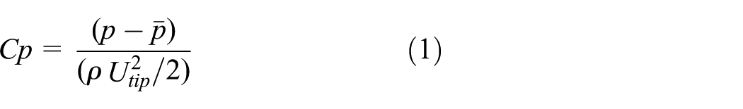

where p is the instantaneous pressure at each measuring point,
The time of the pressure pulsation was characterized by the rotational periodic multiplier of the impeller (M) as follows 14

where t is the acquisition time at any point, and T is the time taken by the impeller to rotate a circle.
In this article, the pressure pulsation data for the five impeller rotational periods at the measuring points P7, P15, and P17 were analyzed according to the location of the floor-attached vortex.
At the pump impeller inlet
The time-domain characteristic curves of the pressure pulsation in the impeller inlet of the axial flow pump under the large flow conditions with and without the floor-attached vortex are shown in Figure 5. The pressure pulsation at the impeller inlet varies periodically under large flow conditions with and without the floor-attached vortex, and there are four peaks and four troughs in each pressure variation period, indicating that the pressure pulsation in the impeller inlet is mainly caused by the impeller rotation. The peak-to-peak values of the pressure pulsation in the impeller inlet with and without the floor-attached vortex were 0.076 and 0.057, respectively, as shown in Figure 5. When the floor-attached vortex appeared in the pump sump, the peak-to-peak value of the pressure pulsation at the impeller inlet changed the most at different periods. However, after the floor-attached vortex disappears, the peak-to-peak value of the pressure pulsation at the impeller inlet is basically the same at different periods. This result is because the floor-attached vortex enters the impeller, which changes the pressure field at the impeller inlet. With a large amount of energy dissipation, turbulent flow occurs at the impeller inlet.

Time-domain diagram of measuring points at the impeller inlet: (a) without floor-attached vortex and (b) with floor-attached vortex.
At the pump impeller outlet
The time-domain characteristic curves of the pressure pulsation at the impeller outlet of the axial flow pump under the flow conditions with and without the floor-attached vortex are shown in Figure 6. Whether there is a vortex in the pump sump, the pressure pulsation at the impeller outlet is more chaotic than that at the impeller inlet, which is mainly due to the rotor–stator interaction between the impeller and the guide vane at the impeller outlet. The rotor–stator interaction between the guide vane and the impeller is a kind of relative dynamic and static interaction. The root cause of the rotor–stator interaction is due to the rotation of the impeller. The stationary guide vanes become rotated relative to the rotating impeller. Relative to the rotating impeller, the static guide blade as an exciting source will generate periodic excitation on the flow in the impeller outlet. Under the large flow condition with the floor-attached vortex, the pressure pulsation at the impeller outlet changes the most at different times. The maximum peak-to-peak values of the pressure pulsation at the impeller outlet with and without the floor-attached vortex are 0.062 and 0.048, respectively. There were two peaks and two troughs in each impeller rotation period without the floor-attached vortex at the impeller outlet. The shape of the pressure pulsation curve with the floor-attached vortex was worse than that without the floor-attached vortex at the impeller outlet. However, the number of peaks and troughs in each impeller rotation period was different and greater than two when the floor-attached vortex occurred in the pump sump. This mainly is due to the disturbance of the floor-attached vortex to the pressure pulsation, causing the number of peaks and troughs of the pressure pulsation at the impeller outlet to increase, but also is due to the back-flow from the guide vane or the consequence due to the floor-attached vortex rotation.
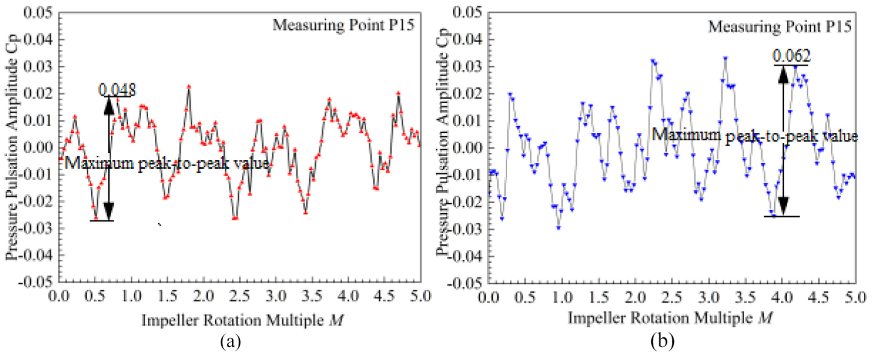
Time-domain diagram of measuring points at the impeller outlet: (a) without floor-attached vortex and (b) with floor-attached vortex.
At the guide vane outlet
The time-domain characteristic curves of the pressure pulsation at the guide vane outlet of the axial flow pump with and without the floor-attached vortex are shown in Figure 7. The peak-to-peak values of the time-domain curves of the pressure pulsation with and without the floor-attached vortex are 0.039 and 0.041, respectively. Due to the rectifying effect of the guide vane, the pressure pulsation amplitudes with and without the floor-attached vortex at the guide vane outlet both decreased greatly. There was no significant difference in the pressure pulsation amplitude at the guide vane outlet under the flow conditions with and without the floor-attached vortex, indicating that the floor-attached vortex had less effect on the pressure pulsation at the guide vane outlet.
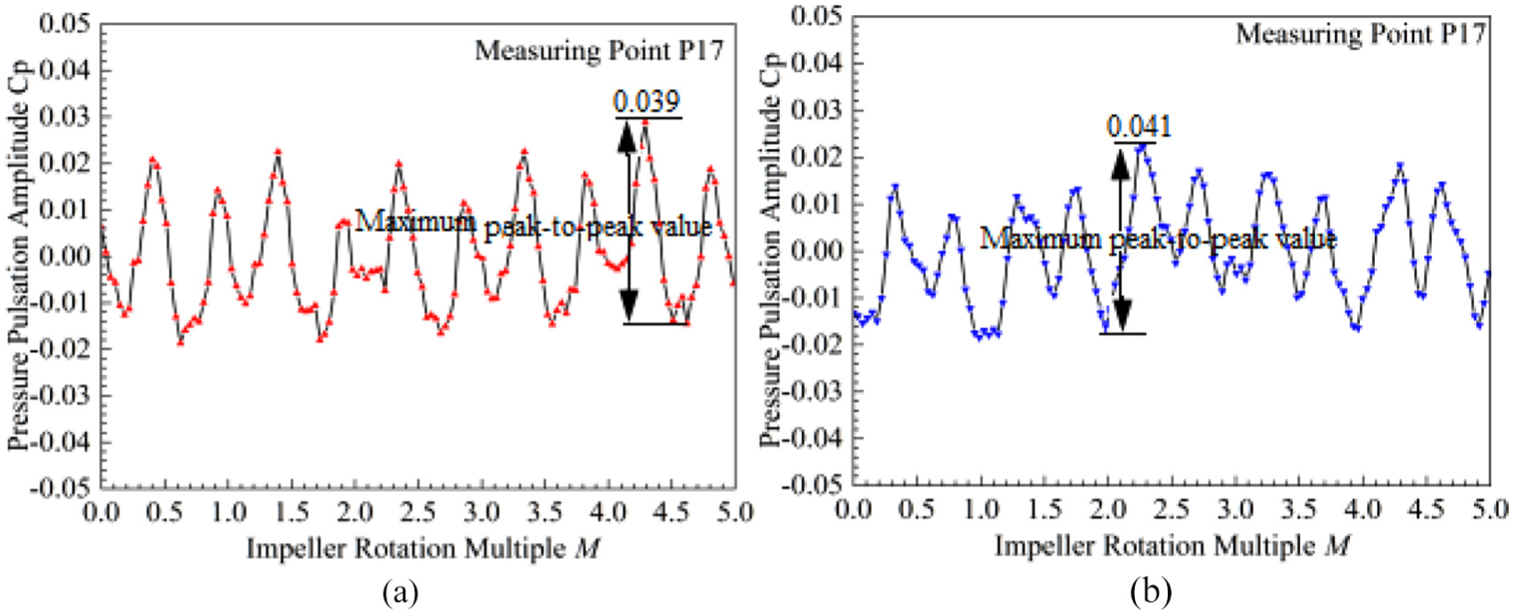
Time-domain diagram of measuring points at the guide vane outlet: (a) without floor-attached vortex and (b) with floor-attached vortex.
Frequency domain of the pressure pulsation
The influence of the floor-attached vortex on the pressure pulsation was further explored by analyzing the frequency domain of the pressure pulsation with and without the floor-attached vortex. Therefore, the pressure pulsation experimental investigation data were transformed by fast Fourier transform and processed by Origin 9.0 software to obtain the frequency-domain characteristic diagrams of the pressure pulsation, as shown in Figures 8–13.

Frequency-domain diagram of pressure pulsation at the impeller inlet: (a) without floor-attached vortex and (b) with floor-attached vortex.
The low frequency of pressure pulsation at the impeller inlet with and without the floor-attached vortex.
Frequency-domain diagram of pressure pulsation at the impeller outlet: (a) without floor-attached vortex and (b) with floor-attached vortex.

The low frequency of pressure pulsation at the impeller outlet with and without the floor-attached vortex.
Frequency-domain diagram of pressure pulsation at the guide vane outlet: (a) without floor-attached vortex and (b) with floor-attached vortex.

The low frequency of pressure pulsation at the guide vane outlet with and without the floor-attached vortex.
At the impeller inlet
The frequency-domain characteristics of the pressure pulsation at the impeller inlet under large flow conditions with and without the floor-attached vortex are shown in Figure 8. The main frequency of the pressure pulsation at the impeller inlet is four times the impeller rotation frequency because the flow field at the impeller inlet is affected directly by the impeller rotation. The excitation source of the pressure pulsation at the impeller inlet is the rotating impeller. Under large flow conditions with a floor-attached vortex, the pressure pulsation at the impeller inlet is more turbulent than that without a floor-attached vortex. The main frequency amplitude of the pressure pulsation fluctuates alternately between the different measuring points at the impeller inlet. The maximum pressure pulsation amplitude at the impeller inlet with the floor-attached vortex is 0.0169, which occurs at the measuring point P7 corresponding to the position of the floor-attached vortex. The main frequency amplitudes of the pressure pulsation at measuring points P5, P6, and P7 near the area of the floor-attached vortex changed obviously because the floor-attached vortex enters the inside of the impeller, producing periodic pressure pulsation on the flow field at the impeller inlet, affecting the stability of the pressure field in the impeller inlet. With the dissipation of the vortex energy, the floor-attached vortex disappears, and the pressure fluctuates continuously at the measuring point P7 where the vortex is located until the floor-attached vortex completely disappears.
According to Figure 8, there is an obvious low-frequency band of the pressure pulsation in one time of the impeller rotation frequency at point P7 where the vortex appears. The frequency-domain diagram of the pressure pulsation at the measuring point P7 is shown in Figure 9. According to Figure 9(b), the low-frequency pulsation amplitude at the measuring point P7 with the floor-attached vortex is significantly higher than that without the floor-attached vortex in the range between 1 and 24 Hz. After deducting the pulsation amplitude induced by the impeller rotation at the pulsation frequency of 2.12 Hz, the low-frequency pulsation amplitude when the vortex occurs is approximately 58.3 times that without the floor-attached vortex, indicating that the frequency of the pressure pulsation induced by the floor-attached vortex is 2.12 Hz in this pump sump. The frequency of the pressure pulsation induced by the floor-attached vortex is low-frequency pulsation. The low-frequency pulsation induced by the floor-attached vortex is closer to the natural frequency of the pump device, and it is very easy to induce the resonance of the pump device. According to the principle of vibration, when the pressure pulsation induced by the intake vortex reaches a certain degree, it will cause great harm to the pump unit. 15 In the pump unit, the strong vibration induced by the vortex can cause structural fatigue due to alternating stress, leading to cracks on key components. Furthermore, when the floor-attached vortex enters the impeller, the instability of the flow field in the impeller increases, causing vibration and hydraulic performance decline of the unit, which is consistent with the phenomenon of the vibration increasing and the efficiency decreasing in the test site.16–17
At the impeller outlet
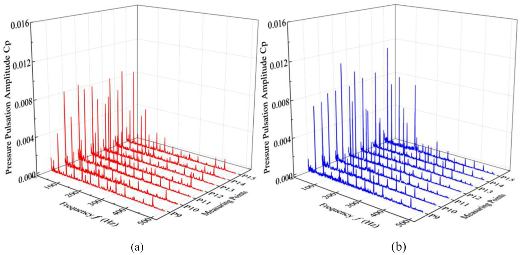
The frequency-domain characteristics of the pressure pulsation at the impeller outlet under large flow conditions with and without the floor-attached vortex are shown in Figure 10. The main frequency of the pressure pulsation at the impeller outlet is twice the impeller rotation frequency; this is different from previous studies that pointed out that the pressure pulsation frequency of the impeller outlet is the blade passing frequency of the impeller. This is because the impeller speed is high in this article, which causes the rotor–stator interaction between the impeller and the guide blade to be high. The pressure pulsation of the impeller outlet is more influenced by the effect of the rotor–stator interaction than that of the impeller rotation, which causes the main frequency of the pressure pulsation to deviate from the blade frequency. The static guide vane relative to the rotating impeller becomes the hydraulic excitation for the flow field at the impeller outlet, which changes the flow field structure at the impeller outlet and increases the turbulent kinetic energy of the flow, so the pressure pulsation at the impeller outlet is more violent than that at the impeller inlet. The pressure pulsation amplitudes at the impeller outlet at different measuring points under the flow conditions with the floor-attached vortex vary more greatly than those without the floor-attached vortex. The maximum pressure pulsation amplitudes at the impeller outlet with and without the floor-attached vortex are 0.0082 and 0.0118, respectively. The maximum pressure pulsation amplitude with a floor-attached vortex is larger than that without a floor-attached vortex at the impeller outlet.
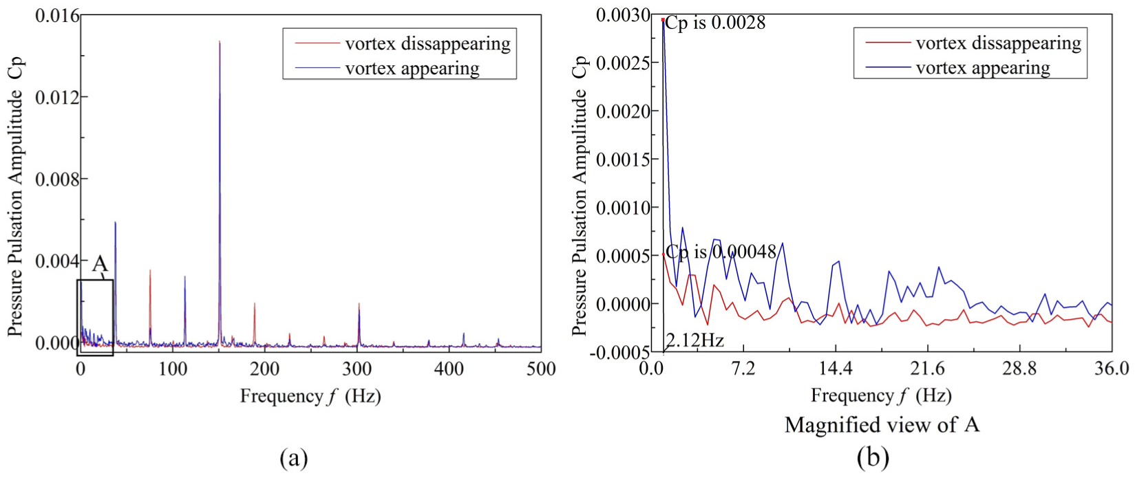
According to Figure 10, there is also a low-frequency band of the pressure pulsation in one time of the impeller rotation frequency at point P15 at the impeller outlet. The amplitude of the low-frequency pulsation at the impeller outlet at the frequency of 2.12 Hz with the floor-attached vortex is 1.8 times that without the floor-attached vortex (Figure 11), indicating that the floor-attached vortex can also affect the pressure pulsation at the impeller outlet, but the pulse amplitude at the impeller outlet is obviously weakened by the rotating effect of the impeller rotation.
At the guide vane outlet
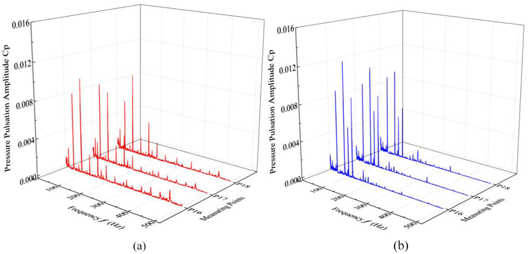
The frequency-domain characteristics of the pressure pulsation at the guide vane outlet under large flow conditions with and without the floor-attached vortex are shown in Figure 12. After the rectification of the guide vane, the pressure pulsation amplitudes of different points at the guide vane outlet have become uniform. The main frequency of the pressure pulsation at the guide vane outlet is twice the impeller rotation frequency. The excitation source of the pressure pulsation at the guide vane outlet is the velocity circulation at the guide vane outlet. The maximum pressure pulsation amplitudes with and without the floor-attached vortex at the guide vane outlet are 0.0091 and 0.0116, respectively. This result is because there is great velocity circulation at the guide vane outlet that leads to the difference in the pressure pulsation at the guide vane outlet. There is little difference in the frequency-domain characteristics of the pressure pulsation at each measuring point at the guide vane outlet.
All the low-frequency pulsations were in one time point of the impeller rotation frequency at different measuring points at the guide vane outlet with and without the floor-attached vortex (Figure 13). The complexity of the flow field at the guide vane outlet leads to low-frequency pulsation at the guide vane outlet, which affects the stability of the flow field. The pressure pulsation frequency-domain curves of the measuring point P17 were selected to analyze the frequency pulsation characteristics of the pressure pulsation at the guide vane outlet when the floor-attached vortex appears and the vortex disappears. Figure 13 shows that there is no significant difference between the low-frequency pulsation amplitude at the guide vane outlet when the vortex appears and the pulsation amplitude when the vortex disappears, indicating that the flow field at the guide vane outlet was not affected by the floor-attached vortex. The low-frequency pulsation at the guide vane outlet is mainly due to the complex velocity circulation of the guide vane outlet.
Main frequency characteristics of the pressure pulsation
The main frequency amplitude of the pressure pulsation was used as the evaluation criteria for the pressure pulsation test to further explore the influence of the floor-attached vortex on the pressure pulsation in the axial flow pump. The main frequency amplitudes of the pressure pulsation at different positions in the axial flow pump under large flow conditions with and without the floor-attached vortex are shown in Figure 14.

Main frequency amplitude diagram of pressure pulsation at the different measuring points: (a) impeller inlet, (b) impeller outlet, and (c) guide vane outlet.
At the impeller inlet
The main frequency amplitude of the pressure pulsation at the impeller inlet is shown in Figure 14(a). When there is no vortex in the pump sump, the main frequency amplitude of the pressure pulsation at different locations along the circumference of the impeller inlet is uniform. However, there is a great difference between the amplitudes of the pressure pulsation at different positions along the circumferential direction of the impeller inlet when the floor-attached vortex appears in the pump sump, the pressure pulsation amplitude decreases from the measuring point P1 to the measuring point P2 and smoothly fluctuates from P2 to P5, and the pressure pulsation amplitude from the measuring point P6 to the measuring point P8 rises first and then decreases. The pressure pulsation amplitude at measuring point P7 corresponding to the floor-attached vortex appearing area is very high. This is because through experiments, the result that the floor-attached vortex located at the low pressure region corresponding to the measuring point P7 has been found. 12 The pressure pulsation amplitude at the measuring point P7 is increased 33.1% relative to the average pressure pulsation amplitude when the floor-attached vortex appears in the pump sump. This is because the floor-attached vortex occurred before the impeller inlet causing disturbance to the surrounding flow field around measuring point P7 and changing the stable structure of the flow field at the impeller inlet that induces violent pressure pulsation of the flow field, so the pressure pulsation amplitude at measuring point P7 increases sharply.
At the impeller outlet
The main frequency amplitude of the pressure pulsation at the impeller outlet is shown in Figure 14(b). The main frequency amplitude of the pressure pulsation at the impeller outlet is basically the same under large flow conditions with no floor-attached vortex. The pressure pulsation amplitude at the impeller outlet along the circumferential direction fluctuates greatly when the floor-attached vortex appears in the pump sump. The pressure pulsation at the impeller outlet changes greatly from measuring point P14 to measuring point P15. This is because the floor-attached vortex occurs at the area between the measuring point P14 and the measuring point P15. Under large flow conditions, the floor-attached vortex enters the inside of the pump impeller, which changes the flow structure at the impeller outlet, causing a decrease in the amplitude of the pressure pulsation there. The main frequency amplitude of the pressure pulsation at the measuring point is increased by 20% relative to the mean value of the pressure pulsation amplitude under large flow conditions. However, when the vortex occurs, the pressure pulsation affected by the vortex at the impeller outlet is significantly reduced relative to the impeller inlet. This shows that the floor-attached vortex also affects the pressure pulsation at the impeller outlet.
At the guide vane outlet
The main frequency amplitude of the pressure pulsation at the guide vane outlet is shown in Figure 14(c). The pressure pulsation amplitude at the guide vane outlet is smaller than that at the impeller outlet, which is due to the rectifying effect of the guide vane. The change trend of the main frequency amplitude of the pressure pulsation along the circumferential direction at the guide vane outlet under the flow conditions with the floor-attached vortex appearing and disappearing is consistent. After the rectifying effect of the guide vane, the influence of the floor-attached vortex on the pressure pulsation at the guide vane outlet disappears.
Pressure pulsation induced by the floor-attached vortex
According to the Biot–Savart Law, 18 the equation of the pressure pulsation induced by the floor-attached vortex is adopted here, which can be deduced as following

where N is the number of pressure data, ρ is the density of water, Γ is the vortex intensity, ω is the rotation angular velocity of the vortex, ti is the time corresponding to each pressure, and r is the radius of the flow field induced by the floor-attached vortex.
The theoretical curve of the pressure pulsation induced by the floor-attached vortex was obtained, as shown in Figure 15. The pressure pulsations induced by the floor-attached vortex in the pump sump change periodically in the form of a trigonometric function.
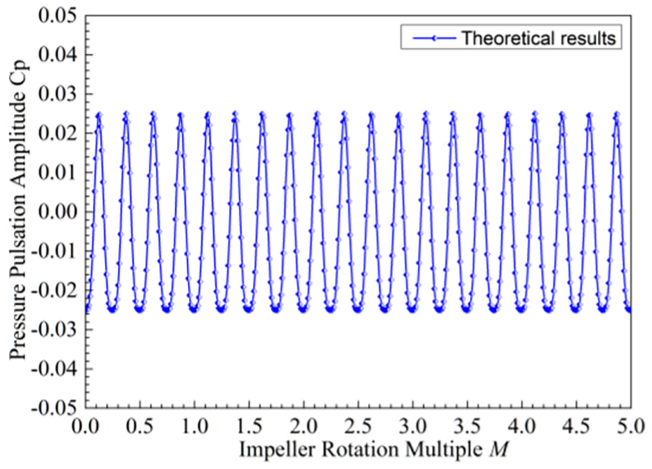
Theoretical results of the floor-attached vortex-induced pressure pulsation.
To obtain the pressure pulsation characteristics induced by the floor-attached vortex of the axial flow pump at different positions in the experiment, the instantaneous amplitude of the pressure pulsation with the floor-attached vortex was deducted from that without the floor-attached vortex to obtain the curves of the pressure pulsation characteristics induced by the floor-attached vortex at the impeller inlet and outlet and the guide vane outlet, as shown in Figure 16.

Experimental results of the floor-attached vortex-induced pressure pulsation: (a) impeller inlet, (b) impeller outlet,and (c) guide vane outlet.
The curve of the pressure pulsation induced by the floor-attached vortex at the impeller inlet fluctuates periodically with time, as shown in Figure 16(a). The curve shape approximates the standard trigonometric function curve, which is very close to the theoretical curve of the pressure pulsation induced by the floor-attached vortex. The pressure pulsation amplitude induced by the floor-attached vortex at the impeller inlet in the test is lower than that in the theory. This is because the vortex intensity in the theoretical formula is constant, and the intensity of the floor-attached vortex changes with time in the experiment. Therefore, there is a certain error between the experimental result induced by the floor-attached vortex and the theoretical result. However, both methods can determine that the pressure pulsation induced by the floor-attached vortex changes periodically in the form of a trigonometric function over time.
The amplitude of the pressure pulsation induced by the floor-attached vortex at the impeller outlet is significantly reduced, the vortex-induced pressure pulsation curve fluctuates periodically with time, and the curve shape approximates the trigonometric function curve. There is a certain difference between the pressure pulsation curve in the experiment and the theoretical curve at the impeller outlet due to the rotation of the impeller, as shown in Figure 16(b). The pressure pulsation amplitude induced by the floor-attached vortex at the guide vane outlet is very small and does not change significantly with time, which fully verifies that the floor-attached vortex has less effect on the pressure pulsation at the guide vane outlet. However, the slight fluctuations in Figure 16(c) are mainly caused by the slight instability of the flow conditions. According to the vibration theory, the periodic pulsation can affect the safe operation of the pump unit, so this study can provide a basis for better eliminating the damage of the floor-attached vortex to the pump device.
Conclusion
The pressure pulsation test under large flow conditions with and without the floor-attached vortex was carried out to obtain the pressure pulsation characteristics induced by the floor-attached vortex at the impeller inlet and outlet and the guide vane outlet in the axial flow pump unit.
The pressure pulsation in the axial flow pump is mainly affected by the impeller rotation. The main frequency of the pressure pulsation at the impeller inlet is the blade frequency, which is independent of whether there is a floor-attached vortex in the pump sump. The number of pressure pulsation peaks and troughs at the impeller inlet without the floor-attached vortex is equal to that of the impeller blades in one rotating period of the impeller, but the number of peaks and troughs increased with the floor-attached vortex, which is larger than that without the floor-attached vortex. The pressure pulsation at the impeller inlet changes the most at different periods with the floor-attached vortex in the pump sump. The pressure pulsation amplitude at the impeller inlet with the floor-attached vortex is larger than that without the floor-attached vortex. The main frequency amplitude of the pressure pulsation at the impeller inlet is increased by 33.1% relative to the average pressure pulsation amplitude. The flow field at the impeller outlet is also affected by the floor-attached vortex. However, the influence of the floor-attached vortex on the pressure pulsation at the impeller outlet was obviously reduced, and the main frequency amplitude of the pressure pulsation was increased by 20.2%. Due to the rectifying effect of the guide vane, the floor-attached vortex has little effect on the pressure pulsation at the guide vane outlet.
The pressure pulsation induced by the floor-attached vortex is a low-frequency pulsation of 2.12 Hz, which varies periodically with time in the form of a trigonometric function. The pressure pulsation amplitude at the inlet of the impeller is the largest, and the shape of the pressure pulsation curve induced by the inlet vortex approximates to the trigonometric function, which is very close to the theoretical analysis results. The low-frequency pulsation amplitude at the P7 measuring point with the floor-attached vortex is approximately 58.3 times that without the floor-attached vortex. At the impeller outlet, the low-frequency pressure pulsation induced by the floor-attached vortex still changes periodically with time, and the amplitude of the pressure pulsation induced by the floor-attached vortex decreased obviously under the influence of the impeller rotation. Due to the steady flow of the guide vane, the amplitude of the pressure pulsation induced by the floor-attached vortex is very small.
Footnotes
Handling Editor: Pietro Scandura
Declaration of conflicting interests
The author(s) declared no potential conflicts of interest with respect to the research, authorship, and/or publication of this article.
Funding
The author(s) disclosed receipt of the following financial support for the research, authorship, and/or publication of this article: This work was partly supported by the National Natural Science Foundation of China (51279173), “The 12th Five-Year” Key Project of National Science and Technology Support Plan (2015BAD20B01), and the Jiangsu Water Conservancy Science and Technology project (2017031).