
Abstract
Pump-controlled hydraulic systems can effectively eliminate throttling losses, but one issue is the unequal flow rate through an asymmetric actuator, which is widely used in hydraulic systems. In this study, a new concept of asymmetric pump is presented, which is a kind of swash plate axial piston pump, with four ports, that intakes and discharges oil twice in one revolution cycle. According to the area ratio of a single-rod cylinder, λ, flow rate ratio of its two delivery ports was designed as (1 −λ): λ, and then a basic equation about the distribution method of the asymmetric pump was obtained. Based on that, a fixed displacement dual-acting axial piston pump was designed and manufactured. Simulation and experimental results show that the operation principle of the displacement dual-acting axial piston pump is feasible. Finally, qualitative tests of displacement dual-acting axial piston pump–controlled system were carried out in the laboratory. The test results reveal that displacement dual-acting axial piston pump can be used in a closed-circuit hydraulic system, demonstrating that the analysis of this study might be a groundwork for a new exploration in displacement-controlled systems.
Introduction
The fluid power is widely used to transfer power in many engineering applications such as mobile machines and mining facilities. The advantages of fluid power have been high power density, low inertia, continuously variable power transmission, high smoothness in heavy load low-speed applications and so on. However, the efficiency of fluid power is lower than electrical and mechanical drive units because of throttling losses. 1 So, the displacement-controlled system, also known as the pump-controlled system, has been put forward to eliminate throttling losses. By adjusting the displacement or the drive speed of a pump, the flow rate going through the hydraulic actuator can be well adapted to load requirements.
One difficult problem for pump-controlled system is the differential areas of a single-rod cylinder, which is widely used commonly in hydraulics. Until now, several hydraulic circuit solutions have been developed to compensate the different asymmetric volume flows in and out of the two chambers of a single-rod cylinder. Berbuer 2 introduced a hydraulic transformer for unequal flow rate compensation in 1988. Continued work based on the same principle was done by Lodewyks. 3
In 1994, Hewett 4 patented a closed-circuit displacement control idea. He adopted a variable displacement pump and a low-pressure charge line to deal with the unequal flow rate for the single-rod cylinder. 4 A 2-position, 3-way valve is used to connect the charge line to the low-pressure side of the actuator when volumetric flow compensation is required. A similar closed-circuit solution was developed by Rahmfeld and Ivantysynova, 5 Rahmfeld et al. 6 and Ivantysynova. 7 In 20120, Wang et al. 8 presented a new scheme of a closed hydraulic circuit for a single-rod cylinder. The unequal flow rate is balanced through one of the pilot-operated check valves to the low-pressure side whose pressure is close to the charge pump. Another way to compensate the difference in volumetric flow through the single-rod cylinder is by using a double pump–controlled system. 9
The solutions mentioned above usually require auxiliary valves and pump, which sometimes may result in more complex, expensive and bulky hydraulic systems. To alleviate the above limitations, Quan 10 and Zhang et al. 11 presented an asymmetric pump–controlled system, as shown in Figure 1, in which the asymmetric pump has three ports, namely, ports A–C. The flow rate ratio of ports A–C is designed as λ:(1 −λ):1, in which λ is the area ratio of a single-rod cylinder. Compared to the solutions mentioned above, the asymmetric pump–controlled system has the advantage of small size, compact structure, low cost, kinetic and potential energy recovery.
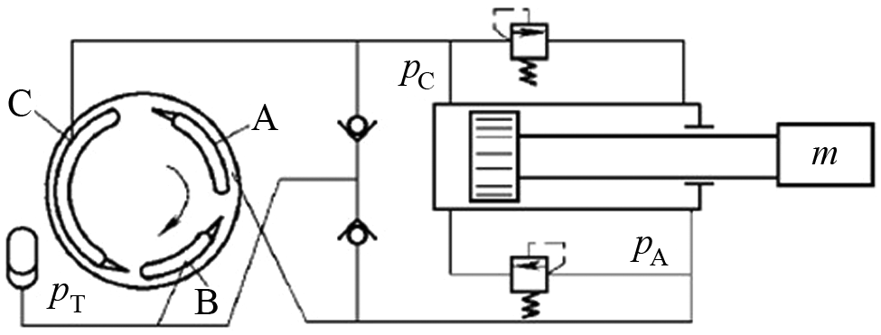
Asymmetric pump–controlled asymmetric actuator.
In this research, continued work based on the same principle10,11 will be conducted, and a new concept of fixed displacement asymmetric axial piston pump (DAAPP) is presented, which has a valve plate with four kidney slots and four ports in the pump casing. Next to a description of the working principle of the DAAPP, the pumping dynamics of it are investigated by means of software package ITI-SimulationX®. Based on computer simulation results, a DAAPP prototype was machined. Then some qualitative tests have been conducted on the test rig.
Operation principle of DAAPP
Basic structure
It is well known that a balanced vane pump has two independent suction and discharge areas and draws and delivers oil twice per revolution. By referring to the working principle of the balanced vane pump, the conventional axial piston pump is redesigned to make it suck and discharge oil twice each cycle.
A schematic diagram of a DAAPP illustrating the basic parts is presented in Figure 2. The cylinder block is rotated by means of drive shaft and is held in contact with the valve plate by a combination of a compression spring and the pressure. A ball-and-socket joint connects the base of each piston to a slipper pad. These slippers are held against the swash plate by a retainer. The angle between the pivot center of the slippers and swash plate rotating center is defined as α, which controls the volumetric displacement of DAAPP.
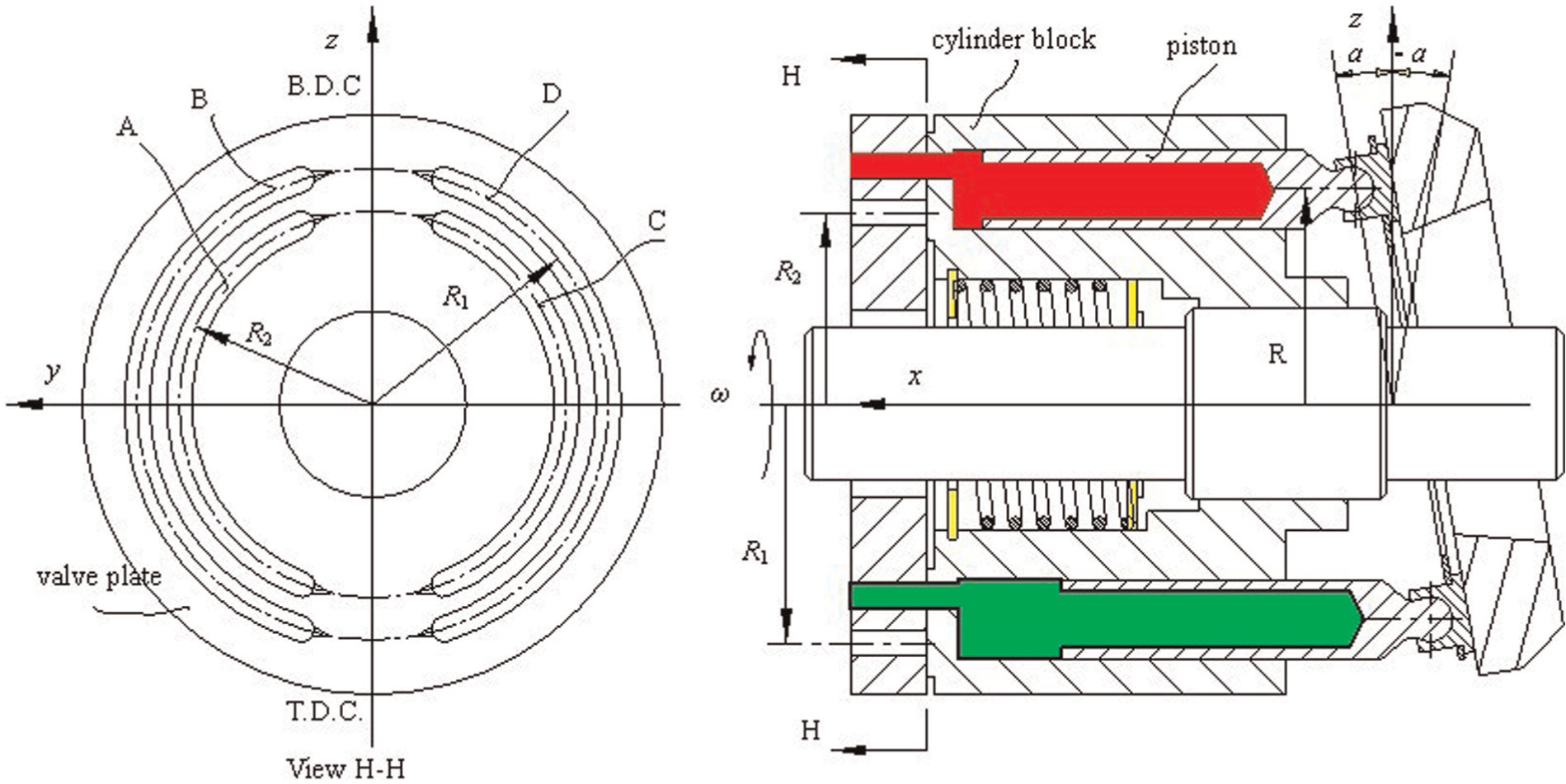
Schematic diagram of DAAPP.
As shown in Figures 2 and 3, the valve plate of DAAPP has four semi-circular slots A–D. Slots A and C constitute an intake/discharge passage, and the pitch radius is R2. Slots B and D comprise another intake/discharge passage, and the pitch radius is R1. Slots A and C and B and D are symmetric about z-axis. V-notched slot is cut at both ends of slots A–D and forms a triangular (V-shaped) flow passage. Thence, DAAPP is a variable, reversible displacement pump. Slots A–D in the valve plate extend through the rear cover, and their cross sections converge into circular cross sections of discharge and suction ports, which are not shown in Figure 1. So, there are four ports in the pump casing, dual inlets and outlets.
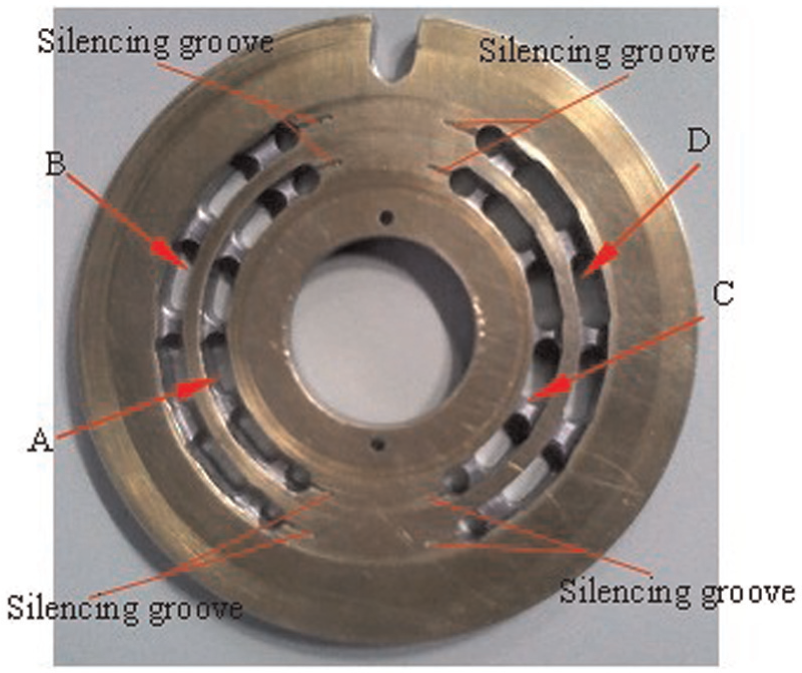
Valve plate of DAAPP.
As shown in Figure 4(a), a plurality of piston bores is provided in annular array at equal intervals in the cylinder block (in this study, the number of the piston bores is 10 because the number of pistons is 10), and the pitch radius of these piston bores is R, which is shown in Figure 2. Opposite each of these bores, and on the surface matching with valve plate, 10 kidney cylinder slots penetrated with 10 piston bores is machined in the cylinder block. To achieve the purpose of DAAPP, the layout of these 10 kidney cylinder slots is designed, as shown in Figure 4(b), and they constitute an inner annular array and outer annular array. The pitch radiuses of these two annular arrays are R1 and R2, which match with the pitch radius of slots A–D in the valve plate. As the cylinder block turns, some piston bores will communicate with slots A and C in the valve plate through the inner annular array of kidney slots; others will communicate with slots B and D in the valve plate through the outer annular array of kidney cylinder slots. As a result, DAAPP withdraws and discharges oil twice independently per revolution. In other words, DAAPP can be used as two independent pumping sources.
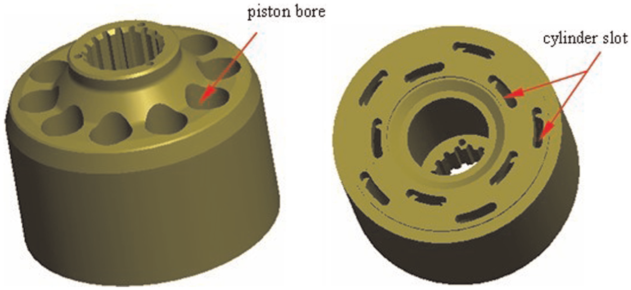
Three-dimensional model of cylinder block of DAAPP.
Distribution method of DAAPP
As shown in Figure 5, slots A and B in the valve plate, which communicate respectively with ports A and B of DAAPP are merged and connected to the bottom chamber of an asymmetric cylinder, slot D communicating with port D is linked with the rod-side chamber of the cylinder and, finally, slot C communicating with port C in the rear cover of the DAAPP is connected to an accumulator.
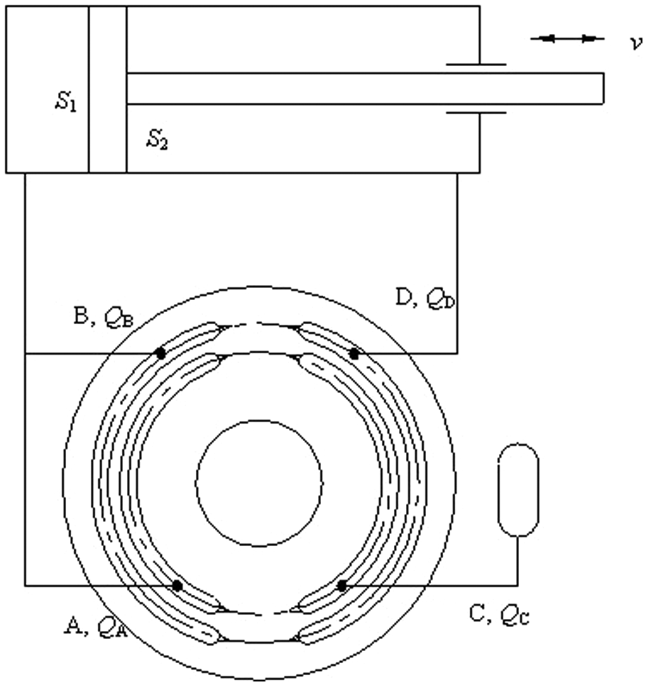
Schematic diagram of DAAPP-controlled asymmetric cylinder.
In Figure 5, the area ratio of a single-rod cylinder is mathematically written as
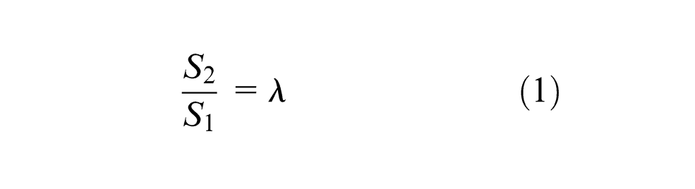
where λ is the area ratio of the single-rod cylinder, S1 is the sectional area of the bottom side of the asymmetric cylinder and S2 is the sectional area of the rod side of the cylinder.
The flow into/out of the bottom chamber of the cylinder is given by the following equation
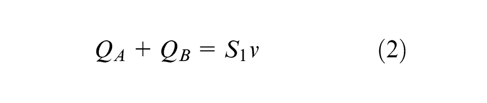
where QA and QB are the intake/discharge flow rate of ports A and B of DAAPP, respectively, and v is extending/retracting velocity of the rod.
The flow out of/into the rod-side chamber of the cylinder is given by the following equation

where QD is the intake/discharge flow rate of port D of DAAPP.
If the leak losses are ignored and fluid is incompressible, there exists


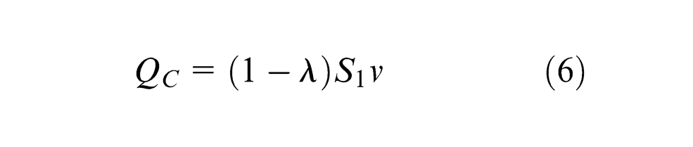
where QC is the intake/discharge flow rate of port C of DAAPP.
Substituting equations (1), (3), (4) and (5) into equation (2) yields the following result for QC
Dividing equation (6) by equation (3) yields the flow rate ratio of ports QC and QD
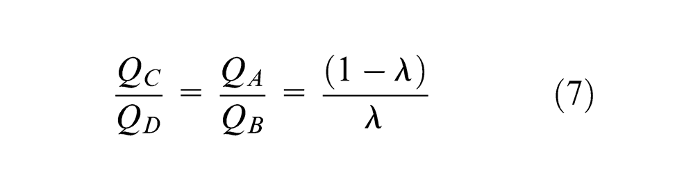
To balance the unequal volumetric flow through a single-rod cylinder in a closed circuit, the ratio of QC and QD should be designed to meet equation (7). Thence, the design of the valve plate is a key factor in designing a DAAPP. Figure 6 shows the sketch of the valve plate of DAAPP. The following assumptions are made: there are a total of N pistons within the cylinder block; among them, the jth pistons, the (j+1)th piston, …, the mth piston, are designed to connect with slots A and C; the rest of the pistons, the ith piston, the (i+1)th piston, …, the (N−m)th piston, are designed to connect with slots B and D.
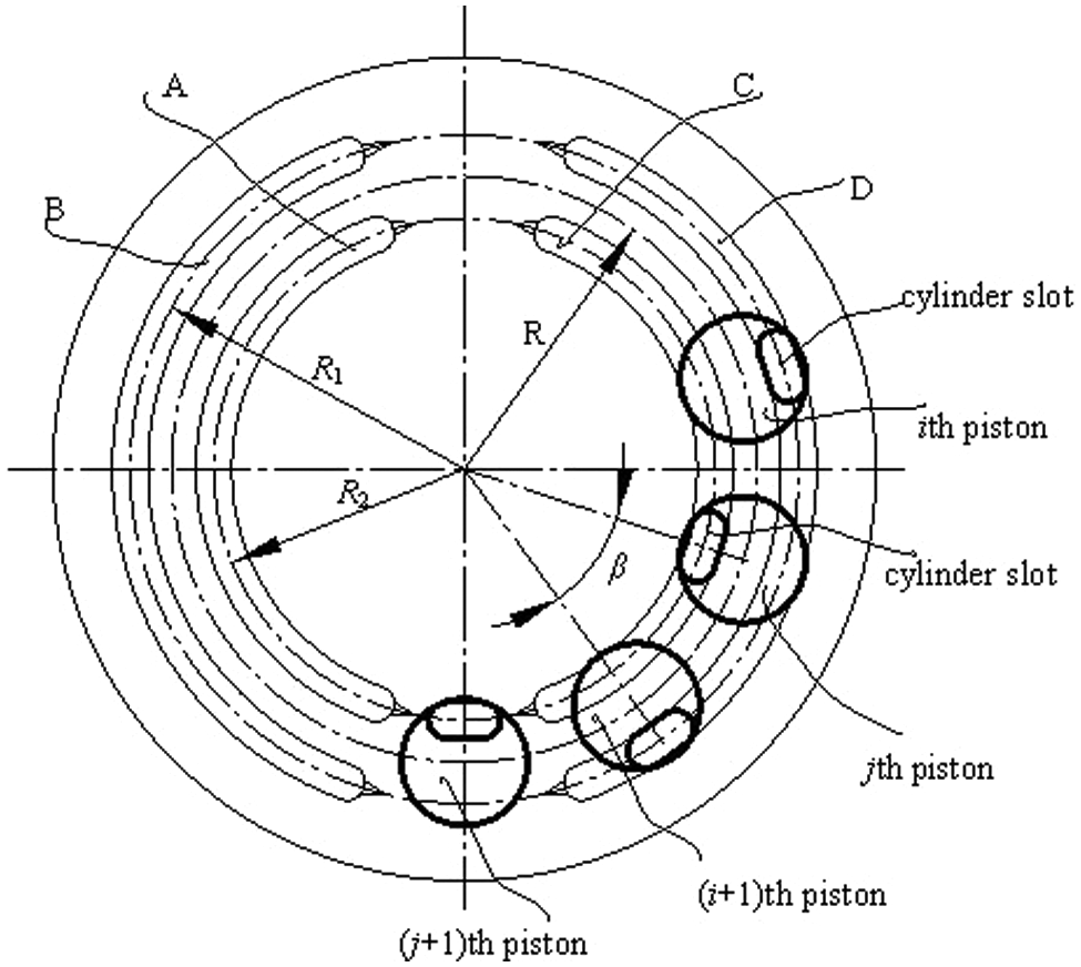
Sketch of the valve plate of a DAAPP.
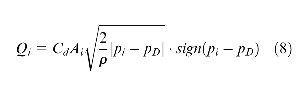
Expression for modelling the discharge/intake flow for the ith piston may be given by the classical orifice equation, which is based on Bernoulli principle
And the flow into/out of the jth piston chamber connected with slots A and C is also given by
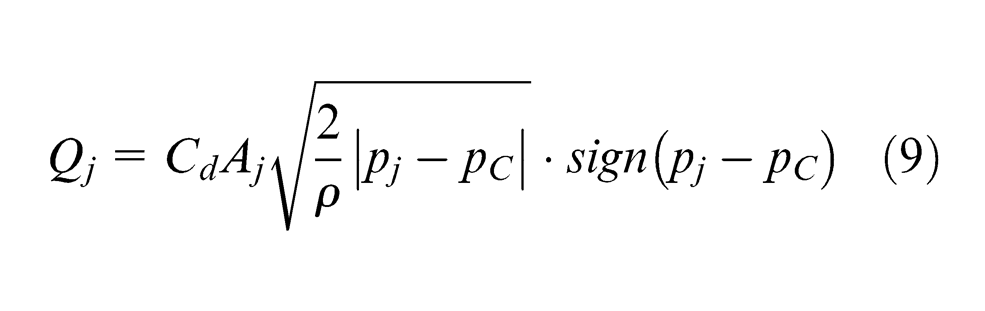
where ρ is the flow density; pD and pC are the discharge pressure at ports D and C of DAAPP, respectively; pi and pj are the pressure within the ith and jth piston chambers, respectively; the dimensionless flow coefficient, Cd, represents the transition between laminar flow and turbulent flow and Ai and Aj are the opening area between the valve plate and the cylinder slot, and it can be calculated with reference to the literature. 12 In this study, they are respectively defined as
where R1 is the pitch radius of slots B and D, and R2 is the pitch radius of slots A and C.
The instantaneous pressure within the ith and jth piston chambers is respectively given by
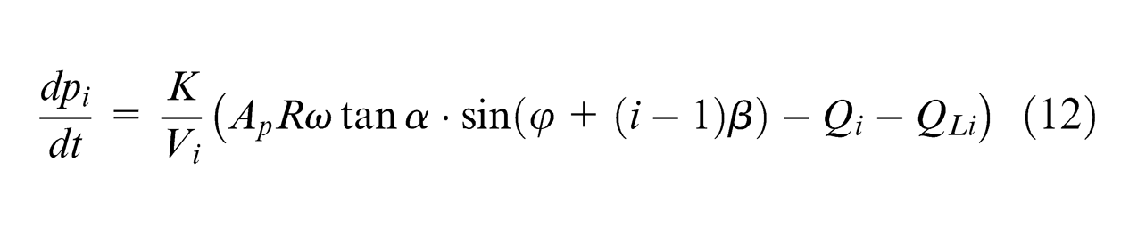
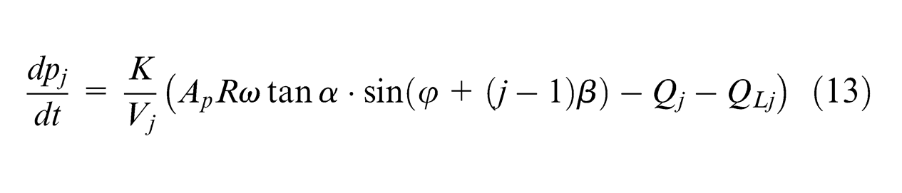
where K is the fluid bulk modulus, Vi is the instantaneous volume of the ith piston chamber, Vj is the instantaneous volume of the jth piston chamber, Ap is the piston area, R is the piston pitch radius, ω is the angular velocity of cylinder block, α is the angle of swash plate, φ is the circular position of the reference piston, QLi and QLj are the leak losses and β is the central angle between two adjacent pistons, which is written as
The total discharge flow of slot D or C is equal to the net flow generated from each piston chamber instantaneously positioned over the slot D or C in the valve plate, written as
Substituting equations (15) and (16) into equation (7) yields equation (17)
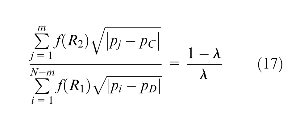
Assuming the fluid is incompressible and pC = pD, then equation (17) may be written as
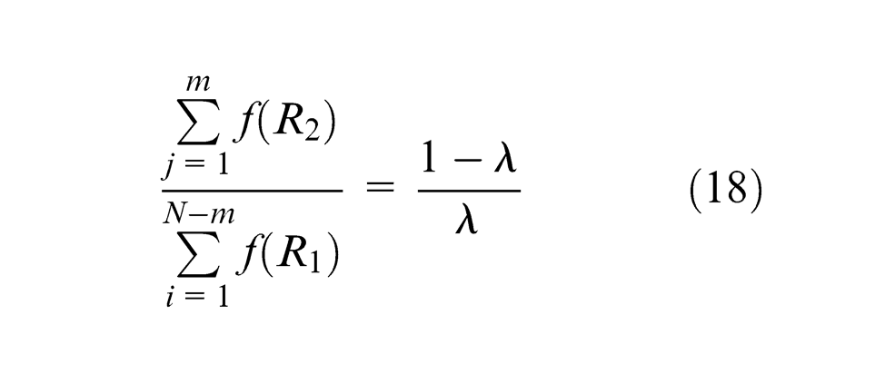
According to equation (18), the number of piston bores connected with slots C and D or R1 and R2 can be adjusted to balance the unequal volumetric flow through an asymmetric actuator.
Simulation of DAAPP pumping dynamics
Simulation model for DAAPP
In this study, a fixed displacement DAAPP was designed, and the swash plate angle α was 18°. If λ = 0.5, then the flow rate ratio of QC and QD should be 1:1. The total pistons within DAAPP were 10. To investigate the pumping dynamics of the DAAPP, a multi-domain modeling and simulation tool ITI-SimulationX package are chosen to develop a model of the fixed displacement DAAPP. In this study, each cylinder is described by a component model subroutine, for example, the ith piston/cylinder and the jth piston/cylinder subroutine simulation models were developed in Figure 7. The simulation model takes into account the flow losses and the compressible volume of oil within cylinder. To assess the importance of interaction between cylinders, a multi-cylinder simulation model of DAAPP was developed to investigate the delivery flow ripple and pressure pulsation. Several of the subroutines detailed in Figure 7 were combined to form a DAAPP model, which was not presented in this research.
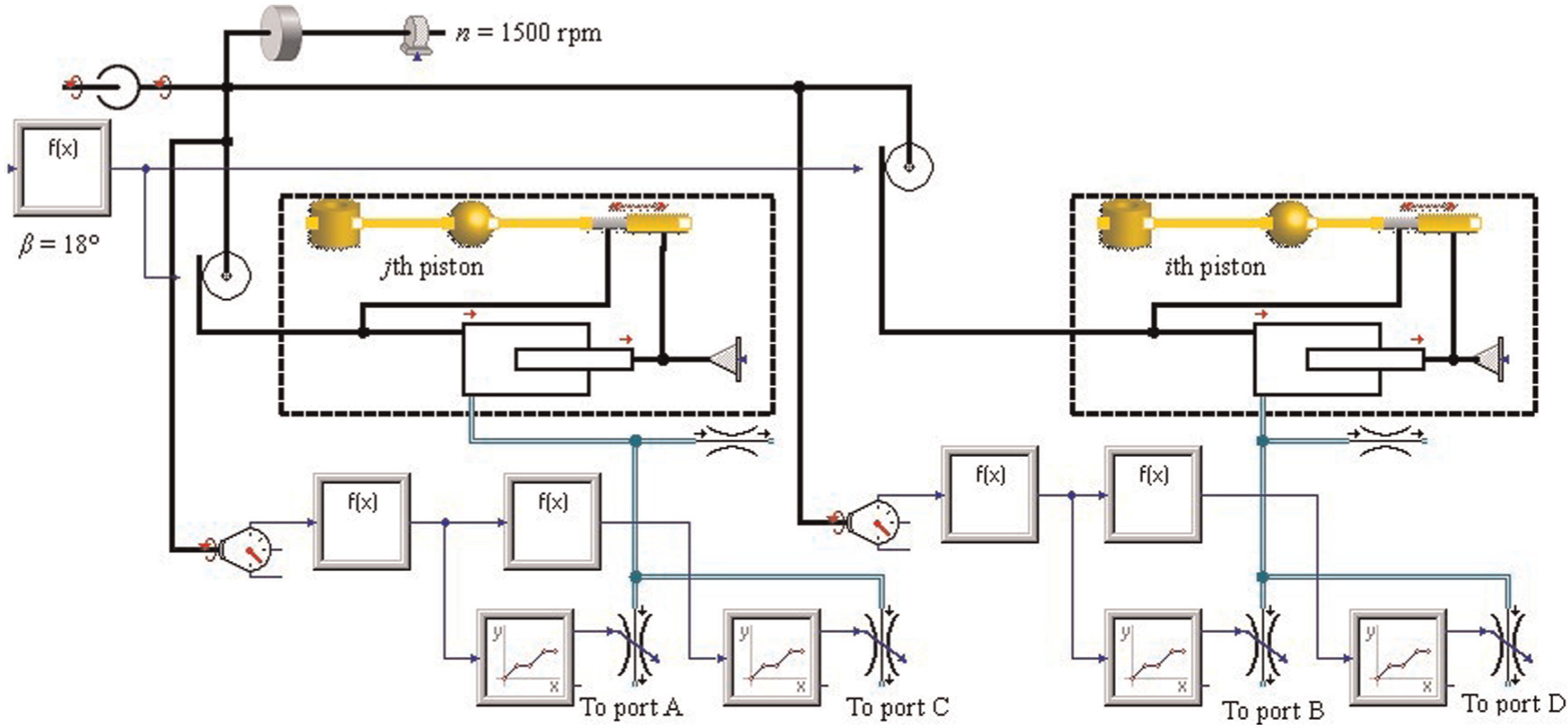
Simulation model of two pistons within DAAPP.
Analysis of simulation results
The following assumptions were made in the simulation calculation as follows: (1) ports A and B were intake ports, ports C and D were discharge ports and the ith and jth piston chambers were designed to connect with ports D and C, respectively; (2) the intake pressure was 0 MPa; (3) the rotational speed n was set as 1500 r/min; (4) the intake and discharge lines were treated as a constant pressure source and sink, respectively and (5) pc and pd were the loads at ports C and D, respectively.
Figure 8 shows the instantaneous pressure and flow characteristics within the ith and jth piston chambers under different conditions. The flow out of the cylinder chamber is considered to be positive direction. It can be observed that the simulation results in Figure 8 are exactly similar to the conventional axial piston pump. It also shows the trapping of fluid in the cylinder at dead centers (top dead center (TDC) and bottom dead center (BDC)), but undershoots or overshoots in cylinder pressure are not severe, meaning that the rates of pressure rising and falling in the cylinders are acceptable. The pressure and flow waveforms within the ith piston follow the same trend as the jth cylinder, but they lag behind those of the jth cylinder by a time shift of 4 ms. The magnitude of cylinder pressure pulsations increases as the load increases.
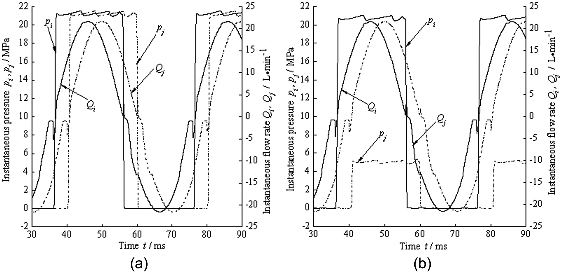
Pressure and flow within the ith and jth piston chambers with different loads at ports C and D: (a) pc = 21 MPa and pd = 21 MPa and (b) pc = 5 MPa and pd = 21 MPa.
In Figure 8, there are two pressure overshoots and two undershoots within the ith and jth piston chambers per one pumping cycle because V-groove is machined at each end of the kidney slot. Two pressure undershoots are not clearly apparent in Figure 8 because their amplitudes are only about −0.03 MPa. As the cylinder approaches the BDC (at the end of suction phase), a pressure undershoot occurs because the flow from the intake port is throttled, which results from the reduction in flow area, associated with the V-groove on the valve plate. As the cylinder passes BDC and moves into the delivery stroke, a transient reverse flow occurs from the delivery port into cylinder, as shown in Figure 8. Then, the fluid in the cylinder is compressed by the reverse flow and the motion of the piston. So the pressure rises quickly and eventually a pressure overshoot occurs.
At the end of delivery phase, the premature reduction of the delivery port flow area leads to a throttling of the piston flow. As a result, a pressure overshoot occurs. In a similar manner to that detailed above, a rapid reverse flow occurs at the beginning of the suction stroke. The initial direction of reverse flow is from the cylinder into the low-pressure intake port. As the cylinder pressure falls, the level of reverse flow reduces. In this case, there is an oscillation in flow rate, as shown in Figure 8. The reverse flow and the piston movement out of the cylinder bore lead to a pressure undershoot.
The simulation results of delivery flow and pressure of ports C and D are presented in Figures 9 and 10. In Figures 9 and 10, the profile shapes of QC, pC are similar to those of QD, pC, respectively. But they have a time difference between themselves of 4 ms. Delivery pressure pulsations and flow ripples occur at even and odd multiples of the piston passing frequency. During one revolution of the cylinder block, there are five pressure pulsations to be generated at ports C and D.
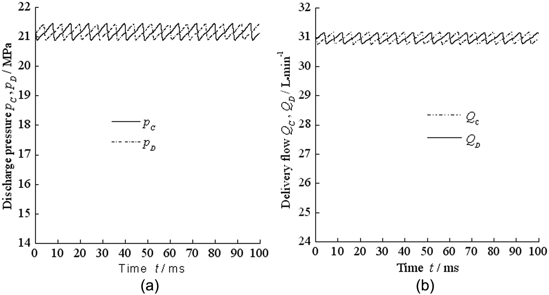
Pumping dynamics at ports C and D when pc = 21 MPa and pd = 21 MPa: (a) discharge pressure at ports C and D and (b) delivery flow at ports C and D.
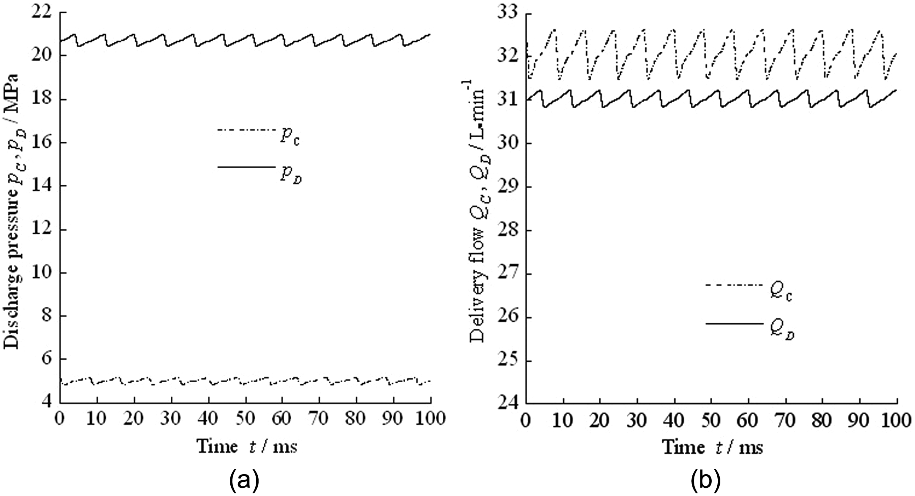
Pumping dynamics at ports C and D when pc = 5 MPa and pd = 21 MPa: (a) discharge pressure at ports C and D and (b) delivery flow at ports C and D.
In Figure 9(a), the magnitude of pressure pulsations of pC is almost the same as that of pD when pc = pd =21 MPa. In Figure 10(a), the magnitude of pressure pulsations of pD is higher than that of pC when pc = 5 MPa and pd = 21 MPa. As detailed in Figure 8, a transient reverse flow occurs from the delivery port into cylinder at the end of suction phase until the fluid within the cylinder is rapidly compressed to the delivery pressure, and thence, the pressure variations as well as pulsation amplitudes of delivery pressure are largely increased as the delivery pressure increases.
According to equation 17, compressibility has an impact on the design of the valve plate of DAAPP. In Figure 9(b), the mean delivery flow of QC is 30.96 L/min, and that of QD is 30.93 L/min when pc = pd =21 MPa; the flow rate ratio of the two outputs is about 1:1. In Figure 10(b), the mean delivery flow of QC is 32.09 L/min when pc = 5 MPa, and that of QD is 31.03 L/min when pc = 21 MPa; the flow rate ratio is about 1.03. From Figures 9 and 10, it may be concluded that compressibility has a little effect on the flow rate ratio of DAAPP’s two delivery ports. Thence, in the design of the valve plate of DAAPP, the fluid can be assumed to be incompressible.
Experimental verification
Test rig
Finally, volumetric efficiency, discharge pressure and noise were measured to verify the feasibility of DAAPP. A fixed displacement DAAPP prototype was manufactured and experimentally evaluated. In the test, ports C and D were discharge ports and ports A and B were intake ports. The test unit was driven by an electric motor and loaded with two pilot pressure relief valves placed close to ports C and D. Figure 11 shows the schematic diagram of the DAAPP test bench, and Figure 12 shows a picture of the laboratory test rig. The electric motor speed can be continuously regulated by an inverter. Pressure sensors were mounted in the DAAPP delivery manifolds, as close as possible to the valve plate. Compared with the dynamic pressure, the dynamic flow is much more difficult to measure. For that reason, the delivery pressure would be used instead of comparison and analysis in this article.
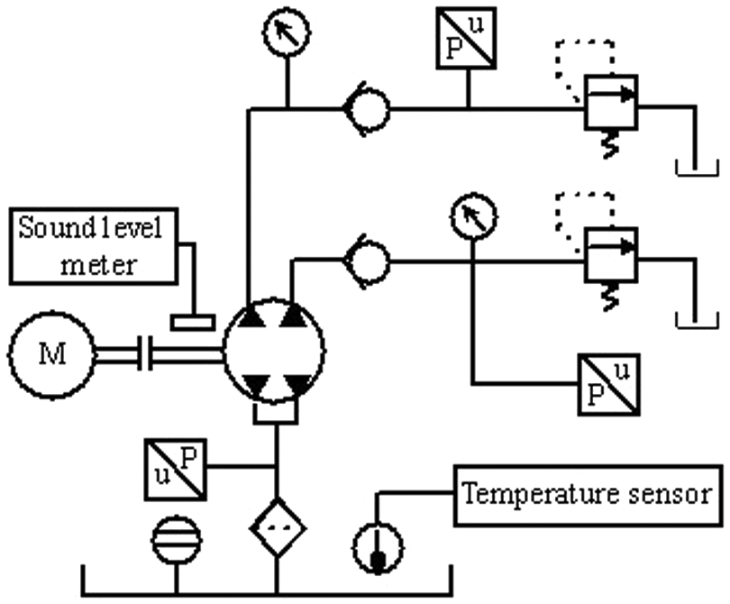
Schematic diagram of the DAAPP test bench.
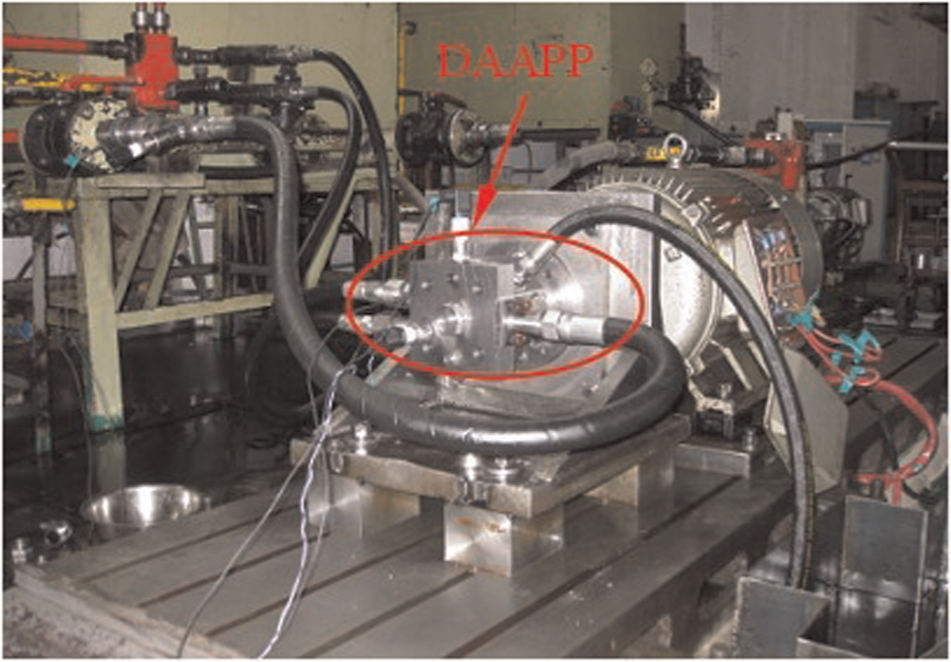
Picture of the test bench and valve plate.
Pumping dynamics test
To verify whether the two ports of DAAPP can discharge independently, delivery pressures of ports C and D under different conditions were performed on the test rig. Figure 13(a) shows the pressure variations of ports C and D at 1500 r/min when pc = 21 MPa and pd = 5 MPa. Figure 13(b) depicts the pressure variations of ports C and D at 1500 r/min when pc = 5 MPa and pd = 21 MPa. From Figure 13(a) and (b), it can be concluded that either of the two ports of DAAPP can discharge flow independently under different testing conditions. Thence, DAAPP can be used to control a single actuator in a closed circuit. It can also be found that discharge pressure pulsations of pC and pD are different when the loads pc and pd are different; a higher load leads to a higher pressure pulsation, which has been explained in Figure 10(a). On the whole, the pressure pulsation amplitude is within an acceptable range. For example, in Figure 13(a), the pulsation amplitude range of pC is from −0.91 to 1.09 MPa (mean delivery pressure of 20.32 MPa).
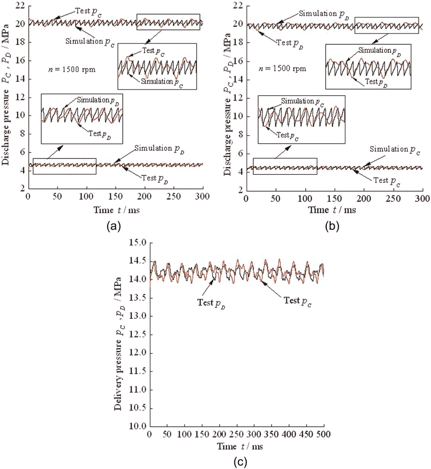
Pumping dynamics at ports C and D of DAAPP under different testing conditions: (a) pc = 21 MPa, pd = 5 MPa, (b) pc = 5 MPa, pd = 21 MPa and (c) pc = 14.5 MPa, pd = 14.5 MPa.
Figure 13(c) shows the measured discharge pressure at 1500 r/min when the two ports were loaded with same loads. It can be found that the measured pressure waveform of pC is similar to that of pD. But the profile of pD lags behind that of pC by a time shift of about 4 ms and pressure pulsations of port D are almost same as that of port C, which are consistent with the simulation results represented in Figure 9(a). Therefore, these measured results demonstrate that the DAAPP can be used as two independent oil power supply pumps.
Finally, it should be noted that pressure pulsations of the calculated pressure profile do not agree with that of the measured pressure profile very well. The error increases as the load increases. The reason may be related to the compressibility in the volume between the manifold and pilot pressure relief valve upstream, which has not been accurately considered in the simulation model.
Figure 14 shows the volumetric efficiency of DAAPP prototype under different discharge pressures. In this case, ports C and D are loaded simultaneously with same delivery pressure. As shown in Figure 14, the volumetric efficiency of port C is almost same as that of port D when the load is less than or equal to 10 MPa. When the pressure is higher than 10 MPa, the efficiency of port D is slightly lower than port C. This phenomenon may attribute to the leakage flow, which increases as delivery pressure increases. At 21 MPa, the efficiencies of both port D and port C are over 0.9. It will also be observed that the volumetric efficiencies do not increase linearly with the increase of load pressure.
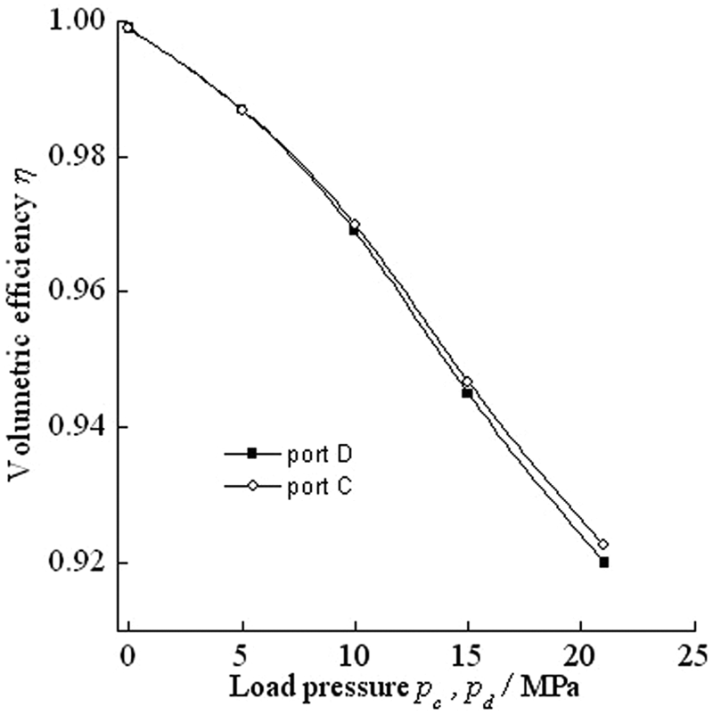
DAAPP volumetric efficiency.
Figure 15 shows the comparison of the DAAPP prototype noise level with ports C and D loaded simultaneously at 5, 10, 15 and 21 MPa at 1000 and 1500 r/min. The sound level meter is located 1 m from the DAAPP prototype. At load pressure ranges from 5 to 21 MPa, the increment of the noise level at 1000 and 1500 r/min is 2.7 and 3.2 dB, respectively. For operating at a speed of 1500 r/min, the measured noise level was about 80.7 dB at 21 MPa. Over the whole span of range, it can be concluded that the noise level increases as the load pressure rises when rotating speed keeps certain and increases as rotating speed increases when the load pressure keeps certain. It is well known that pressure pulsation is one of the principle sources on noise emission in the axial piston pumps. But it is noted that the rotational speed has a more significant effect on noise level than delivery pressure. For example, at rotational speed ranges from 1000 to 1500 r/min, the noise level is increased by 3.8 dB when the delivery pressure is 21 MPa. On one hand, these phenomena may be related with the fixed size of the discharge line and valve in the test system. When the rotational speed increases, the discharge flow rates increase and they would lead to the increase in the pressure pulsations in piston cylinder. On the other hand, it is difficult to completely avoid pressure pulsation in hoses and other sound sources, such as the noise of the motor and coupling effecting on the measured results.
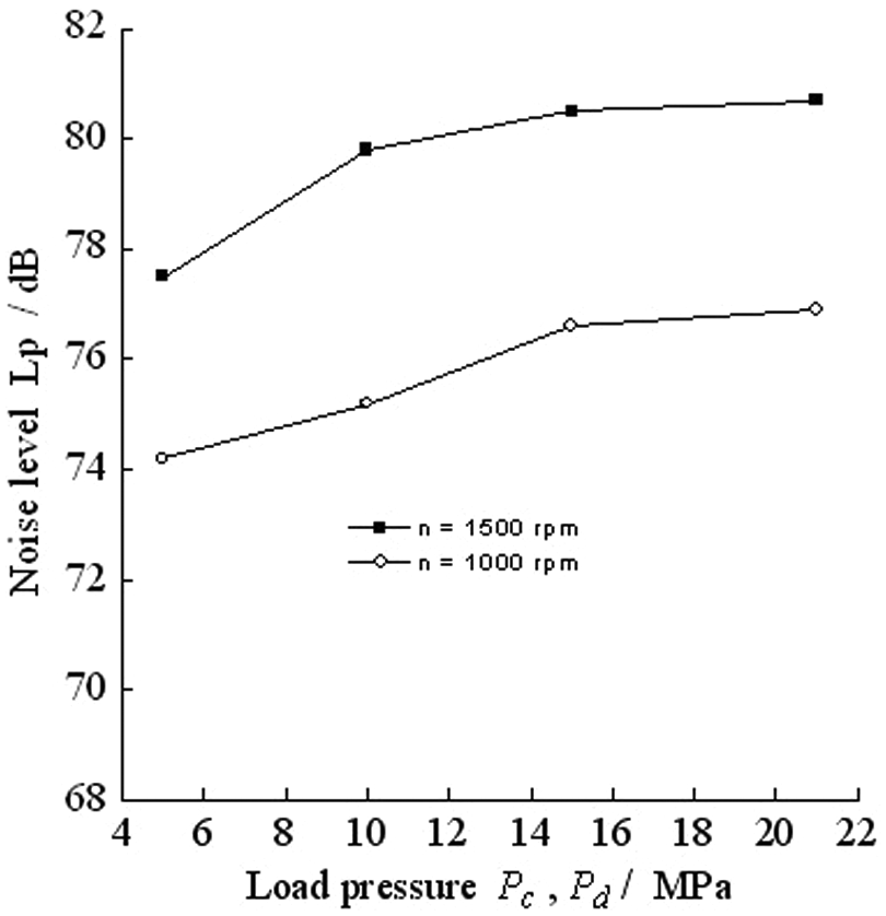
Comparison of DAAPP noise.
Qualitative test of DAAPP used in a closed circuit
To verify whether the DAAPP prototype can be used in a closed-circuit hydraulic system, qualitative test was conducted. The diameters of the rod and the piston are 45 and 63 mm, respectively. The area ratio of the rod side to the bottom chamber side is about 0.49. As shown in Figure 16, during time interval, 1 < t < 2.5, the rod is extending. During 3 < t < 4.5, the motor changes the direction of rotation so that the cylinder is retracting. The maximum velocity is about −402 mm/s when the rod is retracting. When the rod is extending, the maximum velocity is about 396 mm/s. These results reveal that DAAPP can be used in a closed-circuit system.
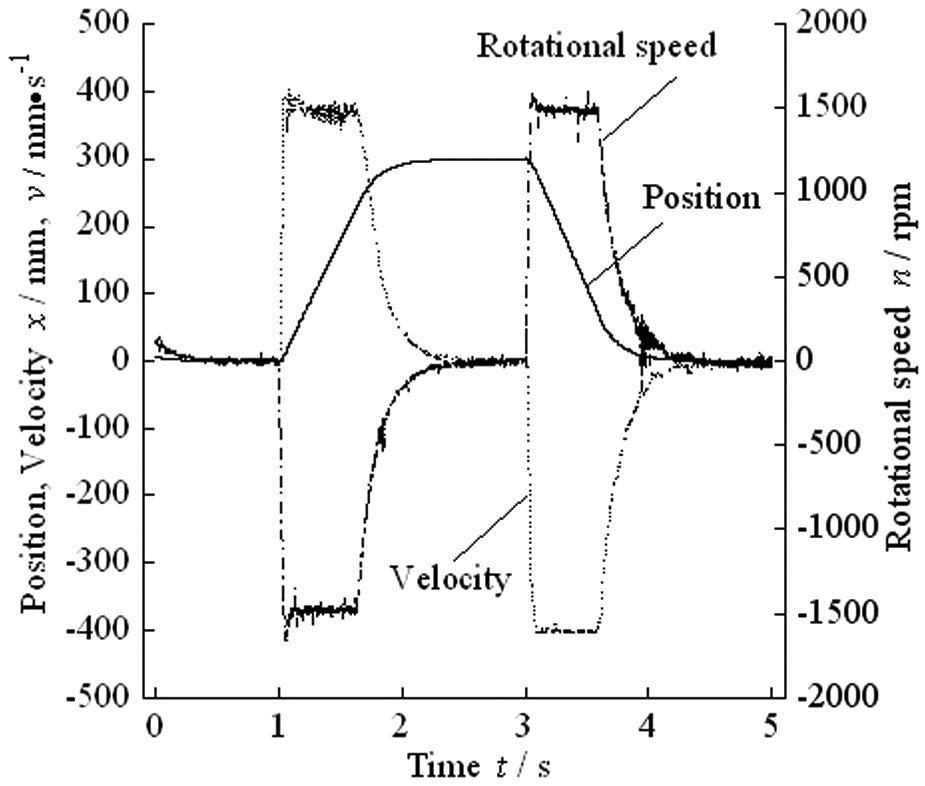
Qualitative test of DAAPP-controlled system.
Conclusion
To implement asymmetric pump–controlled asymmetric actuator in a closed circuit, as shown in Figure 1, a new concept of asymmetric axial piston pump has been proposed for compensating the unequal flow rate of the asymmetric cylinder in a closed hydraulic circuit. The novelty is that the innovative design and configuration of the valve plate in the pump have been provided. The pump has two intake ports and two delivery ports. In one revolution cycle, the pump intakes and discharges oil twice.
A basic equation about the design of the valve plate within DAAPP is obtained. It shows that the flow rate ratio of DAAPP’s two delivery ports can be designed as (1 −λ):λ by adjusting the two pitch radius of the intake/discharge slots in the valve plate, and/or changing the number of piston cylinders connected with the slots under the assumption of incompressible fluid. Further simulation and test results reveal that the operation principle is feasible.
The simulation results show that the compressibility has a little effect on the flow rate ratio of DAAPP’s two delivery ports. Thence, in the design of the valve plate of DAAPP, the fluid can be assumed to be incompressible. If DAAPP is used in a closed-circuit hydraulic system, ports A and B of DAAPP should be merged and connected to the bottom chamber of the cylinder, port D is linked with the rod-side chamber of the cylinder, and finally, port C is connected to an accumulator or tank.
In the future, the design of the valve plate will be optimized to further improve pumping dynamics of DAAPP. Also, the variable displacement components for DAAPP will be researched and designed.
Footnotes
Appendix 1
Declaration of conflicting interests
The authors declare that there is no conflict of interest.
Funding
The research study reported here is supported by Shanxi Province Science Foundation for Youths (Grant No. 2012021021-8) and Open Fund of The State Key Lab of Fluid Power Transmission and Control of Zhejiang University (Grant Nos GZKF-2008006 and GZKF-201113).