
Abstract
This study established a three-dimensional analysis model of the internal flow field of the battery stack with a rotating propeller by using the flow-assisted zinc-nickel battery stack driven by a propeller. The flow of electrolyte in the battery stack was simulated and analyzed. The key design parameters of the battery stack were analyzed and optimized by adjusting the baffle and blade heights, blade speed, and blade number based on the uniformity of the internal flow field of the battery stack. The final simulation results show that the flow field distribution is the most uniform when the baffle and blade are 100 and 140 mm, respectively; from the top of the battery stack, the number of blades is five leaves, and the speed is 600 r/min. This article serves as the basis for the structural design of flow-assisted zinc-nickel battery driven by a propeller.
Keywords
Introduction
The demand for large-scale energy storage equipment is increasing with the large-scale use of new energy sources, such as solar, wind, and tidal energy; hence, developing a highly efficient energy storage device is of great significance.1–3 Liquid battery has broad prospects for development because of its adjustable battery capacity and other prominent advantages. The development of vanadium flow battery is currently the most advanced but still has the problems of low energy density and small working temperature range. 4 Hazza et al. 5 proposed a single-flow battery for electrolyte ion cross-contamination in dual-flow battery. Cheng et al. 6 proposed a flow-assisted zinc-nickel battery to improve the charge and discharge performance of battery. In addition to electrochemical research,7–9 domestic and international scholars investigated the distribution and optimization of the flow field in battery stack.10–12 Most of these studies focused on vanadium flow battery. For example, in the import and export of the channel, Ma et al. 13 proposed to increase the number of the distribution ports of the flow channel, extend the length of the vertical inlet channel, and adjust the width and flow of the flow channel to improve the uniformity of the flow field through computational fluid dynamics (CFD) technology. The optimization of the flow channel of battery stacks has been widely investigated, and the flow channel of the battery stack is generally divided into three types: serpentine, interdigitated, and conventional flow fields. In a study comparing three flow channels, 14 the highest discharge efficiency of the battery and minimal pressure drop were achieved when using the serpentine runner. On this basis, Liu 15 combined the advantages of straight runner and the serpentine flow channel to design a new flow channel by numerical simulation analysis; this method improved the uniformity of the electrolyte between the plates and reduced the flow resistance. Electrolyte transport is not the only key factor that contributes to the low energy density of vanadium flow battery. The flow could be improved by mass transfer polarization. In Zheng et al., 16 a new type of rectangular plug flow battery with plug flow and short flow path is designed to solve the adverse effect of this problem. Song et al. 17 established a three-dimensional (3D) mathematical model to analyze the flow field of flow-assisted zinc-nickel battery stack. The internal flow field and non-uniformity analysis of the original design stack structure are conducted based on the introduction of the inhomogeneity index γ. The effect of the inlet runner on the flow uniformity in different directions of the stack is studied in detail, and a new inlet channel structure 18 with optimized size and quantity is proposed.
In this study, the influence of design parameters, such as the heights of blade and baffle, blade speed, and blade number, is investigated by establishing an internal 3D flow analysis model for a flow-assisted zinc-nickel battery stack with a rotating paddle driven by an external motor. The key design parameters are optimized to provide the basis for the structural design of the flow-assisted zinc-nickel battery driven by a propeller.
Mathematical model
Geometric models and assumptions
Alkaline zincate solution is the electrolyte of flow-assisted zinc-nickel battery. The anode and cathode are inert metal and solid nickel hydroxide, respectively. During charging, the negative electrode undergoes reduction, the zincate ion becomes metal zinc, the positive electrode reacts with nickel hydroxide, and the nickel hydroxide is formed by the nickel hydroxide. The discharge process is the opposite. The internal reactions of the battery stack are as follows:
Reaction of battery cathode

Reaction of battery anode

This study aims to investigate the influence of changing the number and speed of the blades and the baffle and blade heights on the uniformity of the internal flow field of the battery stack without changing the main structure to determine the best combination of parameters. Therefore, the following assumptions are needed when building a 3D analysis model.
During simulation, the plate and electrolyte do not react;
The physical properties of the electrolyte do not change with time;
No heat is transferred between the battery stack and the external environment;
The wall roughness of each part of the model is set equal;
The electrolyte flow in the internal circulation is steady;
The battery internal structure of some small fillet and chamfer and other details are not considered.
The geometry models of the blade and the initial flow-assisted zinc-nickel battery stack driven by a propeller are shown in Figures 1 and 2.

Geometric model of battery stack.

Blade geometry model.
Control equations and basic parameters
The internal electrolyte flow of the battery stack follows the conservation of momentum and mass. Assuming the flow condition as turbulence, the standard k-e model is selected, and the control equation is solved by simple format. The second-order upwind scheme is used in discrete format


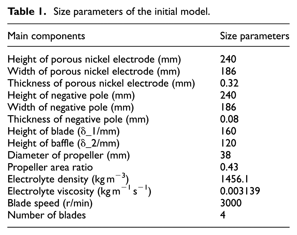
Main components size parameters and related calculation parameters of the initial flow-assisted zinc-nickel battery stack driven by a propeller are shown in Table 1.
Size parameters of the initial model.
Boundary conditions and meshing
The flow of the electrolyte in the battery stack is an internal circulation without inlet and outlet boundary conditions. For boundary conditions, the battery case, inner plate, and baffle are set as the stationary wall conditions, whereas the shaft and blade are the moving wall conditions. The boundary condition has been changed during rotation due to the presence of the blades; hence, the sliding grid is used for the cylindrical area near the blade. The flow field is divided into moving and static regions, which are both subsequently meshed. The two regions pass the parameters through the interface. The unstructured tetrahedral mesh is used in the whole calculation area. The dramatic changes in the parameters within the moving area are considered, and the grid of the moving area is encrypted to further improve the calculation quality of the area near the blade. The final formation of the grid is approximately 2.7 million. The integral flow field grid and moving area encrypted mesh are shown in Figures 3 and 4, respectively.
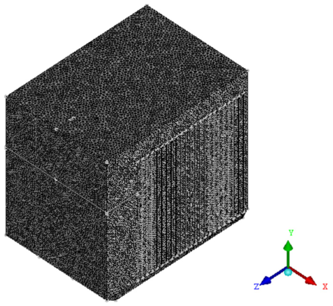
Integral flow field grid.

Moving area encrypted grid.
Simulation analysis and parameter selection
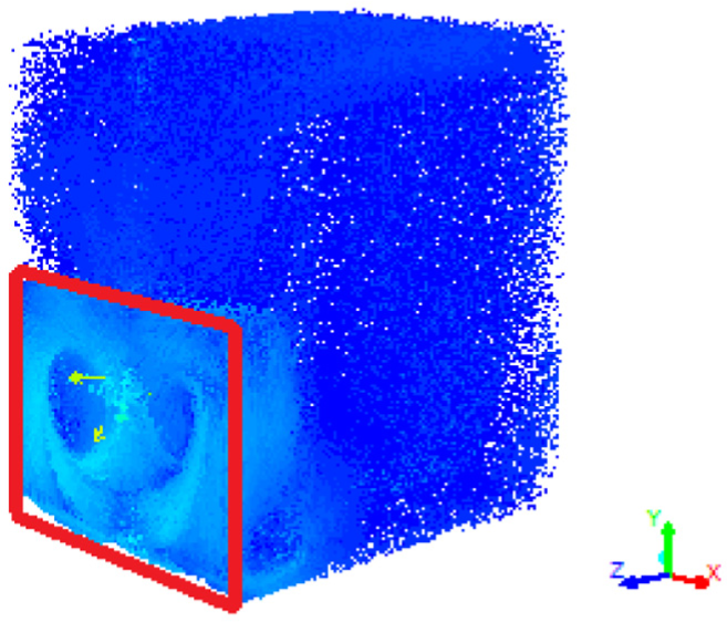
The flow field of the battery stack is solved by Fluent. Figure 5 is the velocity vector diagram of the whole flow field in the battery stack based on the initial design parameters of Table 1. The electrolyte is driven downstream into the main channel by the blade and circulates upward through the battery channel. The simulation results show that eddy currents are formed in the area between the blade and the bottom flow path, and the electrolyte has a large disturbance. Therefore, the velocity distribution of electrolyte entering the trapezoidal channel at the bottom of the battery stack is not uniform, as shown in Figure 6. For the analysis of the uniformity of the electrolyte in the plate flow channel, the six lines used to observe velocity in battery stack are shown in Figure 7. Lines 1, 2, and 3 are in the y-direction, whereas lines 4, 5, and 6 are in the z-direction.
Velocity vector diagram of integral flow field.

Velocity vector diagram of the bottom of battery stack.

Velocity observation line.
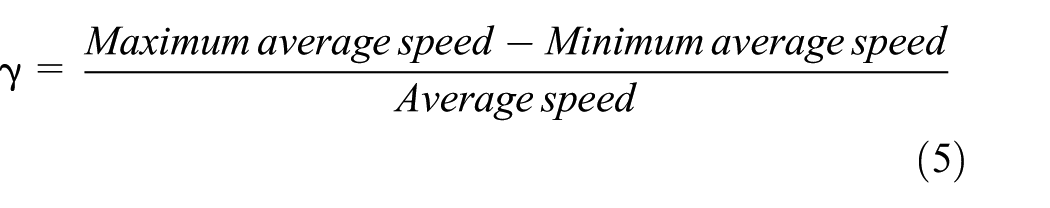
The non-uniformity index γ is introduced, 17 and the distributions of the flow field under different parameters are compared. The non-uniformity indexes in the y- and z-directions of the initial model are 0.278 and 0.4, respectively. The maximum average speed and the minimum average speed in the y-direction are the maximum and minimum speeds of the three observation curves of lines 1, 2, and 3, respectively, and the average speed is the average speed of the three observation curves. The maximum average speed and the minimum average speed in the z-direction are the maximum and minimum speeds on the three observation curves of lines 4, 5, and 6, respectively, and the average speed is the average speed of the three observation curves
Based on the simulation results of the internal flow field of the battery stack, the flow field is not ideal with regard to the following two factors: (1) the blade speed is relatively fast and (2) the distance between the blade and the bottom of the battery is relatively short. These two points cause the electrolyte to hit the bottom of the battery stack at a high speed, resulting in a large number of eddy currents. The main design parameters that affect the internal flow field are the blade and baffle heights, blade speed, and blade number. These parameters can be determined from the simulation and analysis.
The reasonable value and matching of the main design parameters of the initial battery stack are optimized by simulation analysis of the flow field based on the non-uniformity index.
Figure 8(a) shows the change in the non-uniformity index in the y- and z-directions when the blade height is 160, 140, and 120 mm while maintaining the distance between the blade and the baffle. The uniformity of the flow field in the y-direction is larger than that in the original model when the blade is 140 and 120 mm from the top of the battery stack. However, the uniformity of the flow field in the z-direction is poor when δ_1 = 120 mm, in which the blade height is set at 140 mm.

Non-uniformity index of the flow field: (a) Non-uniformity index of flow field at different blade height, (b) Non-uniformity index of flow field at different speeds, (c) Non-uniformity index of flow field at different baffle height and (d) Non-uniformity index of flow field under different number of blades.
Figure 8(b) shows the non-uniformity index in the case of δ_1 = 140 mm, δ_2 = 100 mm, number of blades = 4 leaves, and rotational speed = 3000, 1200, 600, and 300 r/min. The uniformity of the flow field is superior when n = 600 r/min.
Figure 8(c) shows the change in the non-uniformity index at different heights of the baffle. The uniformity of the flow field is superior when δ_2 = 100 mm.
The influence of the blade number on the uniformity of the flow field is investigated when δ_1 = 140 mm, δ_2 = 100 mm, and n = 600 r/min. Figure 8(d) shows the non-uniformity index of three, four, and five leaves and revealed that the uniformity of the flow field of the battery stack is superior when the blade is five leaves.
In this study, the difference between the maximum and minimum values of the non-uniformity index in the same direction is used to measure the influence of the design parameters on the uniformity of the flow field. In Figure 9, the maximum changes in the non-uniformity index under different blade speeds, blade heights, blade numbers, and baffle heights are provided from left to right. According to the uniformity of the flow field of the battery stack, the degree of influence is in the order blade speed, blade height, blade number, and baffle height.

The change of non-uniformity index.
Based on the preliminary screening of blade and baffle heights, blade speed, and blade number, further optimization is conducted with the basic parameters as the blade from the top of the battery stack δ_1 = 140 mm, the baffle from the top of the battery stack δ_2 = 100 mm, the blade speed n = 600 r/min, and the five bladed paddle.
Optimization analysis of parameters
Based on the preliminary screening of the key parameters of the battery stack and on the influence of the main parameters on the flow field, parameter control is used to investigate the influence of each parameter on the uniformity of the internal flow field and determine the optimal value. According to the order of influence, a single parameter is changed while keeping the others constant to investigate and optimize its influence rule.
Optimization of blade speed
While keeping the other parameters unchanged, that is, δ_1 = 140 mm, δ_2 = 100 mm, and five blade leaves, the blade speed is set to 400, 500, 600, 700, and 800 r/min. These cases are simulated and analyzed separately. The speed distribution in the y-direction and the z-direction is given by the rotation speed n = 600 r/min. Figures 10 and 11 show that the flow rate of electrolyte in the battery channel is about 4 cm/s. In the literature, 19 the flow rate of electrolyte in the channel of a flow-assisted zinc-nickel battery driven by a propeller similar to that in this article is also controlled at about 5 cm/s, which is in good agreement with the simulation data obtained in this article. In addition, the velocity of the electrolyte in the plate runner increases with the distance between the plate and blade, whereas the velocity distribution of the electrolyte in the z-direction is relatively uniform. (Note: The velocity distribution of electrolyte in y-direction and z-direction is obtained from the velocity observation line in Figure 7.)

Velocity distribution in the y-direction.
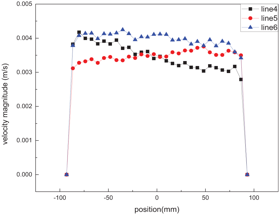
Velocity distribution in the z-direction.
Figure 12 shows that the uniformity of the electrolyte is superior when the blade rotational speed is 400 and 600 r/min. In the y-direction, 600 r/min is excellent, whereas in the z-direction, 400 r/min is suitable. A low electrolyte flow rate indicates significant concentration polarization, whereas a poor electrochemical performance is indicated by the large flow rate at 600 r/min. Hence, the final blade speed is 600 r/min.

Non-uniformity index of flow field for further changing blade speed based on preliminary parameter screening.
Optimization of blade height
The blade height is adjusted while maintaining other parameters constant, such as δ_2 = 100 mm, n = 600 r/min, and five blade leaves. In the simulation analysis, the blade height from the top of the battery stack is 130, 140, 150, and 160 mm. Figure 13 shows the non-uniformity index in the z- and y-directions. The uniformity of the flow field is best when the blade is 140 mm from the top of the battery stack.
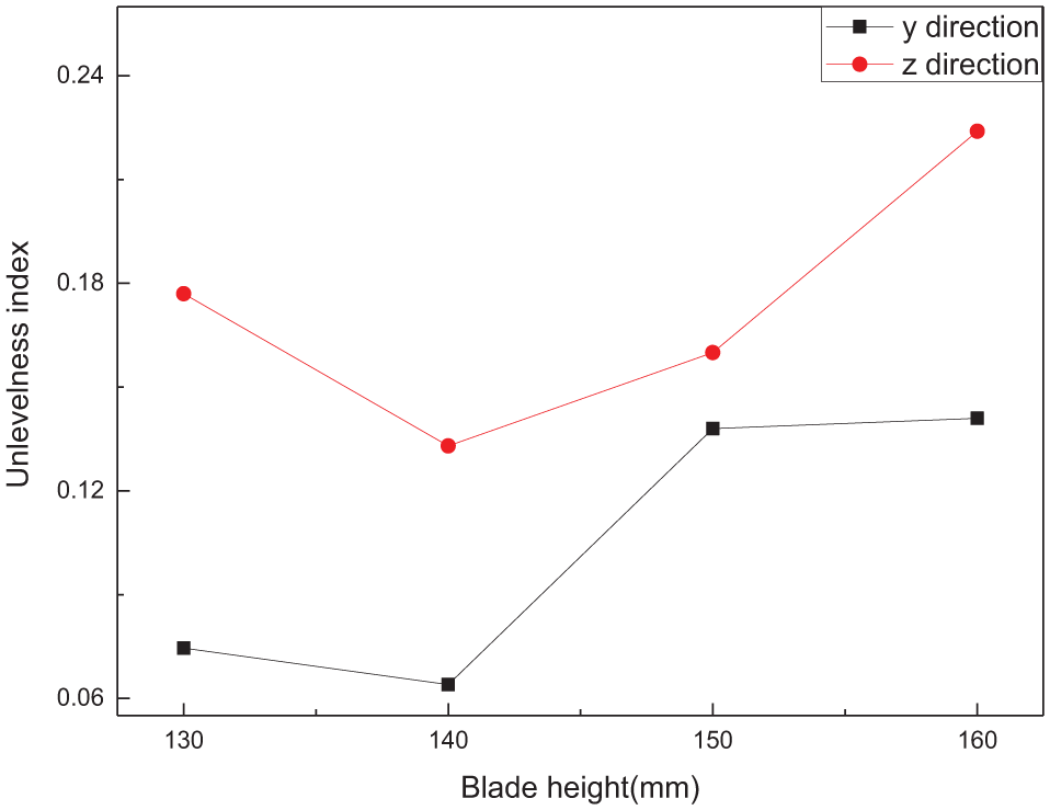
Non-uniformity index of flow field for further changing blade height based on preliminary parameter screening.
Optimization of baffle height
The selection of the blades was conducted during the initial parameter selection; hence, the baffle height is optimized directly. The distance from the baffle to the top of the battery stack is changed while keeping the other parameters constant, such as δ_1 = 140 mm, n = 600 r/min, and five blade leaves. In the simulation analysis, the baffle height from the top of the battery stack is 80, 90, 100, and 110 mm.
Compared with the non-uniformity index shown in Figure 14, the flow uniformity of the electrolyte is best when the baffle is 100 mm from the top of the battery. Table 2 compared the results of flow field uniformity before and after optimization of the battery stack. The results show that after optimizing the other parameters such as blade speed, blade and baffle heights, and blade number, the non-uniformity indexes of y- and z-directions are 0.064 and 0.133, respectively, and the non-uniformity index of y-direction and z-direction is 0.278 and 0.4 respectively. The non-uniformity index in the y- and z-directions decreased by 0.214 and 0.267, respectively, and the uniformity of the flow field was improved.
Comparison before and after optimization.


Non-uniformity index of flow field for further changing baffle height based on preliminary parameter screening.
Conclusion
In this study, a 3D flow field analysis model is established for the flow-assisted zinc-nickel battery stack driven by a propeller. The influence of blade and baffle heights, blade speed, and blade number on the uniformity of the flow field inside the battery stack was investigated through numerical simulation. The key design and structural parameters were optimized. The following conclusions are drawn:
The factors affecting the flow uniformity of the electrolyte are (a) blade and (b) baffle heights, (c) blade number, and (d) blade speed, with the rank of importance as d, a, c, and b.
The internal flow field is optimized and analyzed according to the single variable control method, which is controlled by the influence rank. The best combination of the four design parameters of the flow-assisted zinc-nickel battery stack are δ_1 = 140 mm, δ_2 = 100 mm, n = 600 r/min, and five blade leaves. The non-uniformity indexes of z- and y-directions were 0.133 and 0.064, respectively, indicating that the uniformity of electrolyte distribution is improved.
Footnotes
Handling Editor: Jiin-Yuh Jang
Declaration of conflicting interests
The author(s) declared no potential conflicts of interest with respect to the research, authorship, and/or publication of this article.
Funding
The author(s) received no financial support for the research, authorship, and/or publication of this article.