
Abstract
For laminated beams connected by Coulomb friction, interlayer slippage occurs when interfacial shear stress exceeds the resistant friction stress. Then, the physical properties of the laminated beams will change and may even cause structural damage. In this article, the law of interlayer slippage of laminated beams is obtained by mechanical derivation, and the finite element model is used for comparison verification. First, the internal shear force calculation formula of the laminated beam considering the interlaminar friction is derived from the segment micro-element method. Second, interlayer slippage laws of the frictional laminated beams in both horizontal and longitudinal direction are derived according to the hierarchical slip determination conditions. Third, according to the state quantity of different boundary conditions, the transfer matrix method is used to solve the longitudinal length of interlayer slip. Then, the design of the algorithm program is completed by MATLAB. Finally, based on the comparison between the finite element model calculation results and the calculation results of the algorithm program, the accuracy of the proposed method is verified. The analysis results indicate that slippage destroys the integrity of the laminated beam section and reduces the bending moment of inertia of the slip section of the beam. The influence of slip effect on the frictional laminated beams should be considered in deflection calculation.
Keywords
Introduction
For bridge structures, the main part is the beam. The beam can be considered as a laminated structure with myriad of fine fiber layers. The bending mechanism of beam is equal to the joint shear resistance of each fiber layer. When the interlayer shear force of Coulomb’s frictional laminated beam exceeds the maximum friction resistance between layers, the interlayer slippage will occur. Taking this into consideration, the slippage phenomenon of laminated structures in practical engineering can be explained. As slippage phenomenon is one key issue for bridge structures, many researchers in the field of civil engineering focus on this problem.
In order to study the interlayer slippage phenomenon of the laminated beam, the researchers did lots of work from two perspectives, one is the theory about beams and the other is the simulation model about beams.
For the theory about beams, some researchers introduced theory to the issue, and some are developed currently theory. Murakami 1 presented a Timoshenko beam theory with built-in interlayer slip, in which he recovered Newmark’s Euler–Bernoulli beam theory 2 by introducing the kinematic constraint of zero shear strain and provided a failure modes model of laminated beams with delamination. Hjiaj et al. 3 were concerned about the large deformation analysis of steel–concrete composite beams and divided the composite beams into the integral part and the sliding part to study the influence of shear flexibility on the overall nonlinear behavior of the composite beams by the co-rotational framework. Aydogdu 4 proposed a new theory of shear deformation for the analysis of static and dynamic behavior of composite beams and compared numerical models under different boundary conditions. Monetto 5 analyzed the mechanical behavior of a three-layer beam in a way of establishing beam model by simulating each layer of the composite beam into a linear elastic Euler–Bernoulli beam and setting the connection stiffness in the transverse direction much more stronger than in longitudinal direction. Based on layerwise displacement theory, Liu and Jeffers 6 proposed a multilayered shell formulation within the framework of isogeometric analysis. Through numerical case, the accuracy of the proposed formulation was proved. When the beam acts as shell or plate, the Kirchhoff theory was introduced. To analyze the Kirchhoff plate, the rational Bezier triangles in isogeometric analysis coupled with a feature-preserving automatic meshing algorithm was proposed by Liu and Jeffers. 7
For the simulation models about beams, there are also many scientists who have put great effort to solve different kinds of issues about the interlayer slip. Karama et al. 8 deduced an exponential numerical model of the composite beam considering the transverse shear stress by the principle of virtual work and analyzed the mechanical behavior of the composite beam according to the model. Krawczyk et al. 9 deduced a geometric nonlinear finite element analysis model of a laminated beam undergoing large deformation, subjected to small strain and moderate interlayer slip by assuming that there was only local interlayer interaction in the laminated beam and proposed that the interface shear stress could be used to define the layer interactions. Queiroz et al. 10 have established an ANSYS finite element model (FEM) to analyze and study the longitudinal slip of steel–concrete composite beams under local interaction and full interaction. Jiang et al. 11 proposed a method to calculate the distribution of the section moment and the shear force of a steel–concrete composite beam based on global–local bending model. Yang et al. 12 simplified the calculation formula for the bending stress and interfacial shear force of the steel–concrete composite beam with interlayer slippage by introducing the stress increasing factor η. Later, in order to capture the plasticity growth in large-deformation frames, a formulation which is used to utilize a layer-based discretization of a distributed plasticity isogeometric analysis frame model was proposed. Through several numerical cases, the performance of the proposed model was assessed. 13
Even though the theory and models are proposed to deal with the issue about the interlayer slip, many of the researchers focus on the effects of interlayer slip on the overall dynamic properties of the structure or on the mechanical properties of the slip component. Less literature discusses the law of interlayer slip of multilayered beams.
This article focuses on the law of interlayer slip between the laminated beam layers and the derivation of related quantitative analysis. First, in order to study the mechanism of slip effect, the shear force in contact layer is derived based on the section analysis method. Then, the horizontal interlayer slippage rule according to Coulomb’s law of friction was presented. Third, based on the transfer matrix method (TMM) and the Laplace transfer method, the program with MATLAB used to calculate the length of longitudinal slippage between frictional laminated beams was proposed. Finally, the ANSYS numerical simulation results are compared to verify the accuracy and efficiency of the proposed program.
The shear force in contact layer
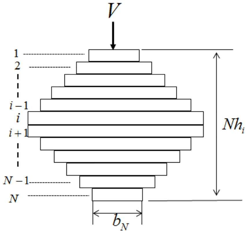
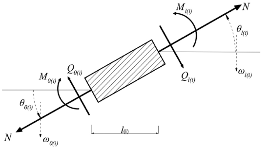
Take the bending segment of the laminated beam with N layers as the research object, as shown in Figure 1. The cross sections of the frictional laminated beams with variable width and equal height are shown in Figure 2.

Bending segment of the laminated beam with N layers.
Cross sections of the laminated beam with variable width and equal height.
When the laminated beam is subjected to forces as a whole structure without interlayer slippage, the shear stress distribution of the segment is uniform. According to theorem of conjugate shearing stress, 14 the shear stress in the beam is

where

For the frictional laminated beams with interlayer slippage, the effect of the interlayer friction between layers should be considered. Assuming that interlayer slippage has occurred in the laminated beam, the cross section of the beam with a height of
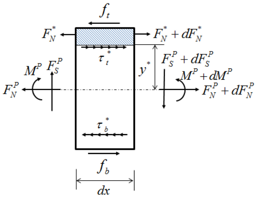
Free-body diagram of one infinitesimal element of the laminated beam.
According to the Euler–Bernoulli beam theory, the equilibrium of the infinitesimal element of the laminated beam in the longitudinal direction conforms to the following equations

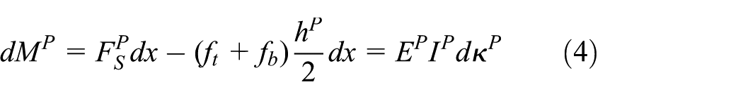
where
For the volume element of the shaded part of the upper laminated beam element, as shown in Figure 4, the equilibrium in the longitudinal direction requires that

where

The development process and rule of slippage in the laminated beam with N layers: (a) state 1: without slippage, (b) state 2: first slippage occurs, (c) state 3: slippage develops, and (d) state 4: slippages occur in all contact layers.

where
Equation (6) is equal to the differential form as follows
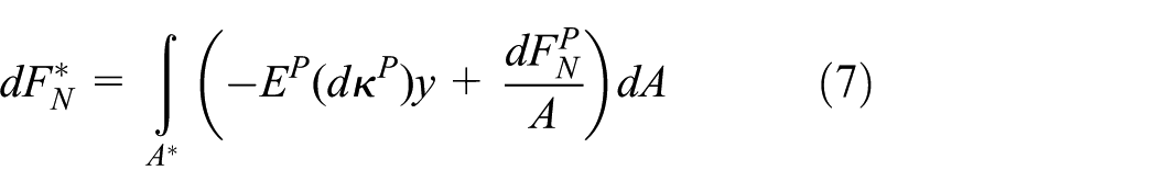
Combining equations (5) and (7)

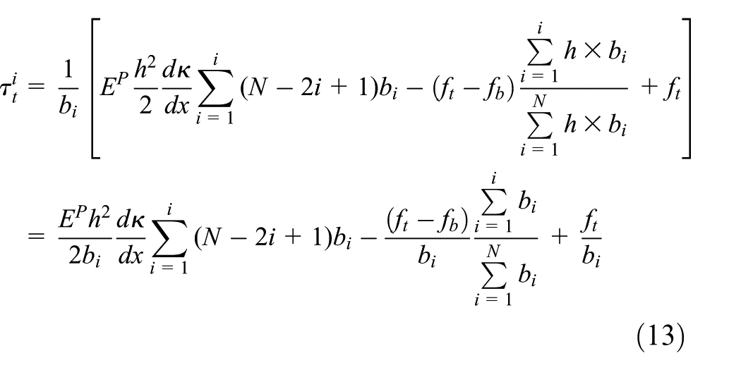
By substituting equations (2) and (3) into equation (8), we deduce the shear stress

where
Similarly, the shear stress

The relative slippage of frictional laminated beam with variable width and equal height is shown in Figure 2. The relative slippage occurs mainly between layers. To accurately illustrate the position of slippage, the definition of contact layer is introduced.
The definition of the ith contact layer represents the contact surface between the ith layer beam and the (i + 1)th layer beam. The static moment and the cross-sectional area in the contact layer can be calculated through following equations


When
When

Horizontal interlayer slippage rule
According to Coulomb’s law of friction,
16
the maximum static friction stress is equal to the kinetic friction stress, and the kinetic friction stress is equal to the product of the normal contact stress

where V is the applied external load and L is the length of the laminated beam. The interlayer slip state discrimination condition satisfies the following relationship 17

State 1: when applying small external load, the laminated beam remains sectionally intact without interlayer slippage. So, the frictional forces acting on the adjacent surface of the upper and lower surface are equal to zero, that is,
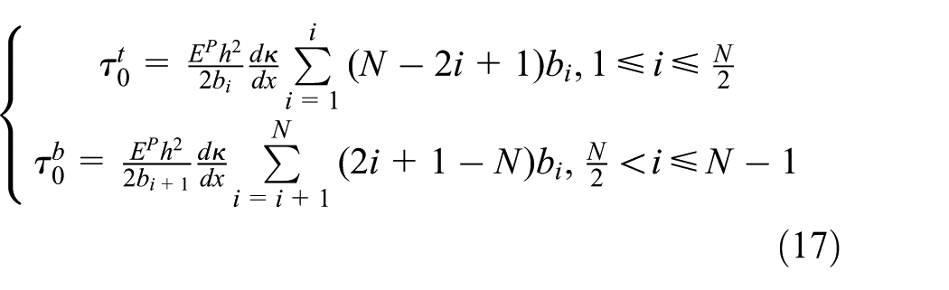
The distribution law of the shear stress and the ultimate friction resistance in non-slip state is shown in Figure 4(a). It can be seen that the shear stress is distributed on the cross section quadratically. Therefore, the interlayer slippage occurs first in the contact layer at the neutral axis.
State 2: the first slippage in the contact layer at the neutral axis occurs as the applied external load increases. Then, the laminated beam section can be divided into top part and bottom part, respectively. Each part can be thought as an independent frictional laminated beam. The shear stress at state 2 can be calculated by equation (18)


The distribution law of the shear stress and the ultimate friction resistance in state 2 after the first slippage is shown in Figure 4(b). It can be seen that after the first slippage, the shear stress presents two symmetrical quadratic distributions. The peak values are located at the upper and lower layers which are close to the overall neutral axis. Therefore, it can be inferred that the second slippage appears symmetrically at the (i–1)th and (i + 1)th contact layers.
State 3: as the applied external force continues to increase, the laminated beam can be divided into three parts when the second slippage occurs, as shown in Figure 4(c). Among the three parts, the top and bottom segments can be seen as single-sided laminated beam subjected to the frictional force, while the middle segment is the double-sided laminated beam subjected to the frictional force. For the single-sided laminated beam subjected to the frictional force, the shear stress can be calculated by equation (18). For the double-sided laminated beam subjected to the frictional force, the shear force can be calculated by equation (19)

where
State 4: from the previous derivation, it can be concluded that the laminated beam will repeat State 3 until all the contact layers appear to slip and become N layers of independent beam without bond, as shown in Figure 4(d). The shear stress is distributed in a zigzag pattern across the cross section and satisfied continuity.
Longitudinal interlayer slippage rule
The relationship between the interlayer slippage and the change ratio of curvature
1. When the first slip occurs, the change ratio of curvature in state 1 can be deduced by combining equations (15) and (17)

2. When the second slip occurs, the change ratio of curvature in state 2 can be deduced by combining equations (15) and (18)

3. The relationship between the change ratio of curvature and the interlayer slippage can be summarized according to induction deduction method

So, the shear force at kth slippage state can be calculated based on the force balance in infinitesimal segment
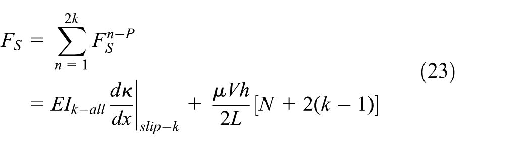
where

where
Calculation of interlayer slip length based on TMM
The longitudinal length of interlayer slippage can be calculated by equations (22)–(24). But, the longitudinal length calculation is related to the boundary conditions of the laminated beam. To establish the solvable function between the whole structure and the boundary conditions, the TMM is introduced.
TMM for beam element considering axial force
Assuming an arbitrarily selected i-unit of the laminated beam structure, the left-end state vector is Si–1 and the right-end state vector is Si. According to the mechanical equilibrium of the unit and assuming the unit and node state vector deliver continuously, the relationship between the leftmost node and the rightmost node in the whole structure can be established18–21
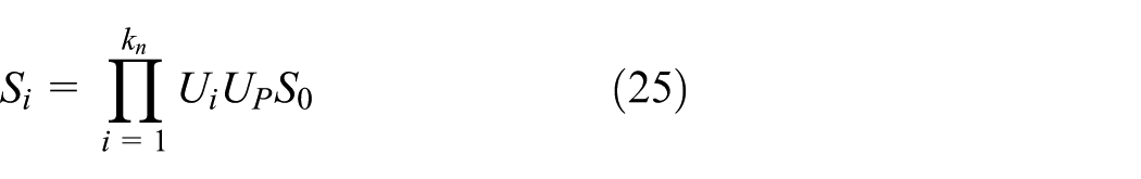
where Ui is field matrix, UP is point matrix, and kn is the total number of units.
The overall stiffness matrix of TMM is the multiplicative form of field matrix and point matrix. This method does not change the dimension of matrix in the process of multiplication, saves computer memory, and is easy to solve. It is especially suitable for solving the mechanics problems of chain structure.
If the beam is subjected to the axial force in addition to the vertical load, the interaction between the axial force and the deflection will inevitably cause the moment balance expression function to produce an additional term.22,23 Ignore the longitudinal displacement of the microbodies and assume that the axial force N acting on the end of the beam is a constant value. The mechanical equilibrium equation of the beam element subjected to the axial force can be deduced.
Select an infinitesimal element of a beam with the length of

Free-body diagram of an infinitesimal element of beam under axial force.
According to the different boundary conditions at both ends of the laminated beam, including the common methods of free end, simple support end, and fixed end, the state quantity of the boundary condition selects different combinations of values, as shown in Table 1.
State quantity of different boundary conditions.

Ignoring the effect of lateral motion on longitudinal motion, 24 the following differential equations can be obtained according to the stress equilibrium of the infinitesimal beam element

Let

Laplace transform is applied to equation (27). Then, the relationship between right-end deflection and left-end deflection of the infinitesimal beam element can be calculated

Combining equations (26) and (28), the deduced relationship between the vertical deflection and other state variables can be derived from equation (29)

Similarly, for the angle of rotation, the moment and shear force can be derived from equation (30).

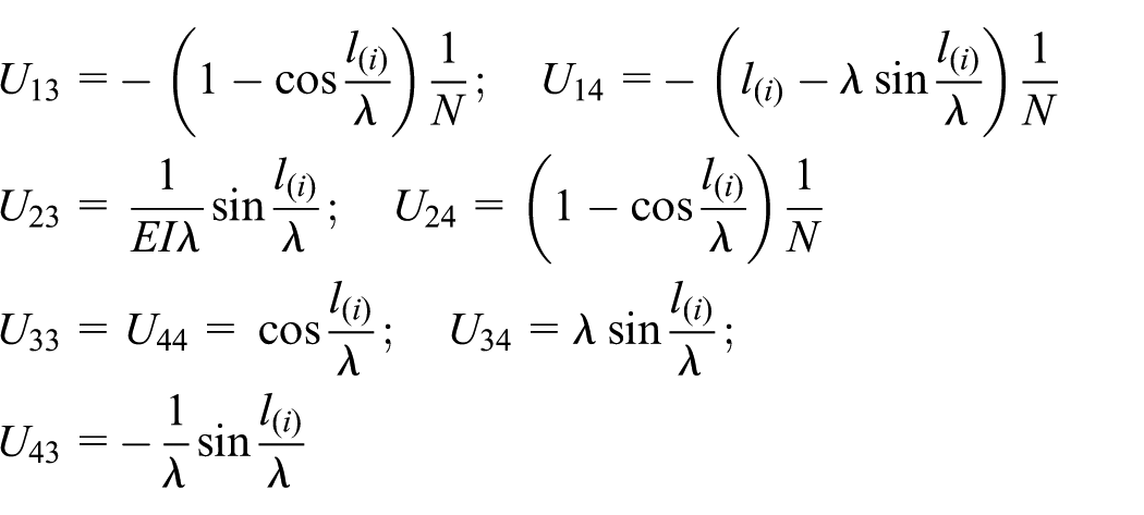
And then, the relationship between the state vectors at both ends of the beam element can be expressed as a matrix form with the transform matrix
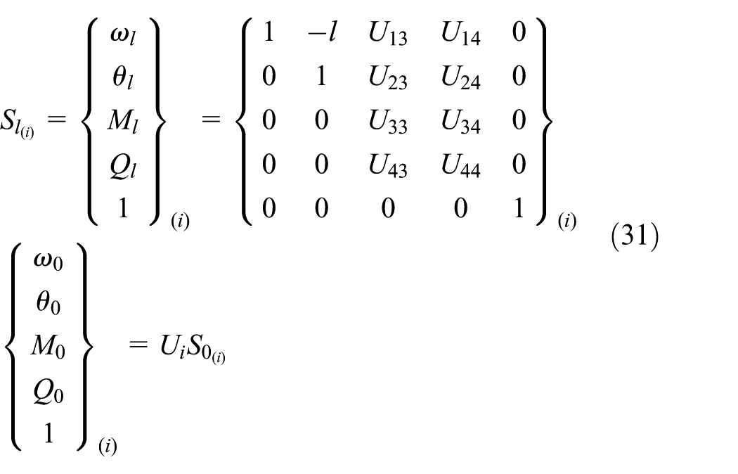
where
Assuming that the whole beam structure is divided into n units, the transfer matrix of the left and right ends of the structure is written as follows

Combining the boundary condition which is shown in Table 1, the basic state vector at the boundary node is obtained by solving the residual matrix. Then, the state vectors of all elements in the beam structure are obtained by the recursion method through the transfer matrix relations of each unit.
Program design of solving slippage length based on recursive algorithm
The parameters of transfer matrix are related to the state of slippage between layers, while the slippage between layers gradually unfolds with the increasing of outer load. Incremental iterative algorithm can be used for calculation. The loading process is divided into multiple load increment steps, the increment of state vector under each load increment step is calculated separately, and the load increment of the current step is added to the calculation result of the previous load step. The algorithm for solving the slippage length is shown in Figure 6.

The main program flow chart and the transfer matrix subroutine flow chart.
Numerical simulation
Take a laminated beam with a span of 5 m as the analysis object. This laminated beam is composed of 11 layers of single-layer beams with a thickness of 7 mm, as shown in Figure 7. The material of the laminated beam of this numerical example is steel, Poisson’s ratio is 0.3, and the elastic modulus is 195 GPa. The beam is fixed at both ends. The initial tension in the beam is 106 N, and a gradually increasing concentration force is applied at the midspan position.
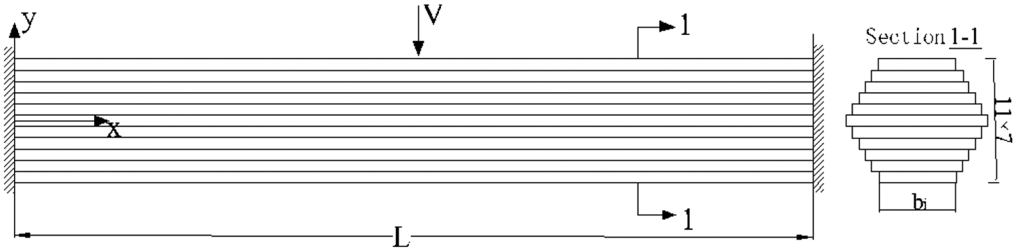
The schematic drawing of the laminated beam.
The width of the laminated beam layers is assumed to be symmetrical and shown in Table 2.
Equivalent beam width of the PWS-91 parallel steel wire cable.

The ANSYS FEM of the laminated beam is simulated by three-dimensional beam element BEAM188 with 6 degrees of freedom (DOF) in the space, and each laminated beam layer is divided into 500 elements in total. The rigid arm unit is established between the units of every two adjacent laminated beam layer elements, and the interlayer contact is simulated through the DOF-coupling of the common node of the rigid arms. Boundary conditions of the laminated beam model are fixed constraints.
Simulate the initial strain by applying axial tension of 106 N. The initial external load is 120 N, and the load increment for each load step is 5 N. The FEM is shown in Figure 8.

Finite element model of the laminated beam.
The moment of inertia of the laminated beam is related to the slippage state, as shown in Figure 9.

Relationship between the slippage state and the cross-section moment of inertia.
According to the presented equations (22)–(24) about slippage, it can be deduced that when the external load reaches 120 N, the laminated beam gets the critical slippage state. To verify the accuracy of the proposed algorithm, the results at different span locations were calculated by ANSYS and compared as shown in Figure 10.

Comparison of the displacements and the shear forces calculated by ANSYS and proposed algorithm: (a) comparison of the displacement results calculated by FEM and the presented algorithm and (b) comparison of the shear force results calculated by FEM and the presented algorithm.
Figure 10 shows that the calculation results of the algorithm are very close to FEM simulation. Due to the rigid girder element in FEM, the shear locking phenomenon occurs and results in the simulation shear force which is smaller than the proposed algorithm, but the numerical errors are very small, as shown in Figure 10(b).
The shear force at the coupling node of the rigid girder element in FEM under the critical slippage state is extracted, that is, the shear force value of the contact layer in the laminated beams can be simulated, and the distribution rule is drawn as shown in Figure 11.

The shear forces of the contact layers in FE model.
Figure 11 shows that the shear force of the laminated beam contact layer is quadratic in the transverse direction and antisymmetric quadratic distribution in the longitudinal direction with respect to the external load application position. The shear force distribution law solved by ANSYS is in accordance with the deduced results of the proposed algorithm.
According to previous equations, the ultimate interlayer friction resistance of this example is 12.3 N. Suppose that the shear force of the rigid girder element in the FEM is the integral of the unit shear stress on the contact layer area, the calculated shear force of the contact layer in Figure 11 shows that the maximum value of the shear force in rigid girder nodes is 11.9 N. Based on the law of interlayer slippage deduced in the previous sections, the first slippage occurs at both the fixed ends and the midspan at the same time with the superimposition of load substeps.
Under the current substep, if the shear force of the contact layer of a finite element unit is greater than the ultimate frictional resistance, then the longitudinal restraint of the coupling node of the rigid girder connected to this element is released and the shear force of the current contact layer is reversely applied to the node for simulating the friction between layers.
The number of slippage elements near the left fixed end in each substep is extracted and described as shown in Figure 12. The result describes the contact layer slippage development process in each of the four higher shear force contour areas. The first all-section slip state of the laminated beam happens in 10th substep and the length of the interlayer slippage at this state is 15 elements.
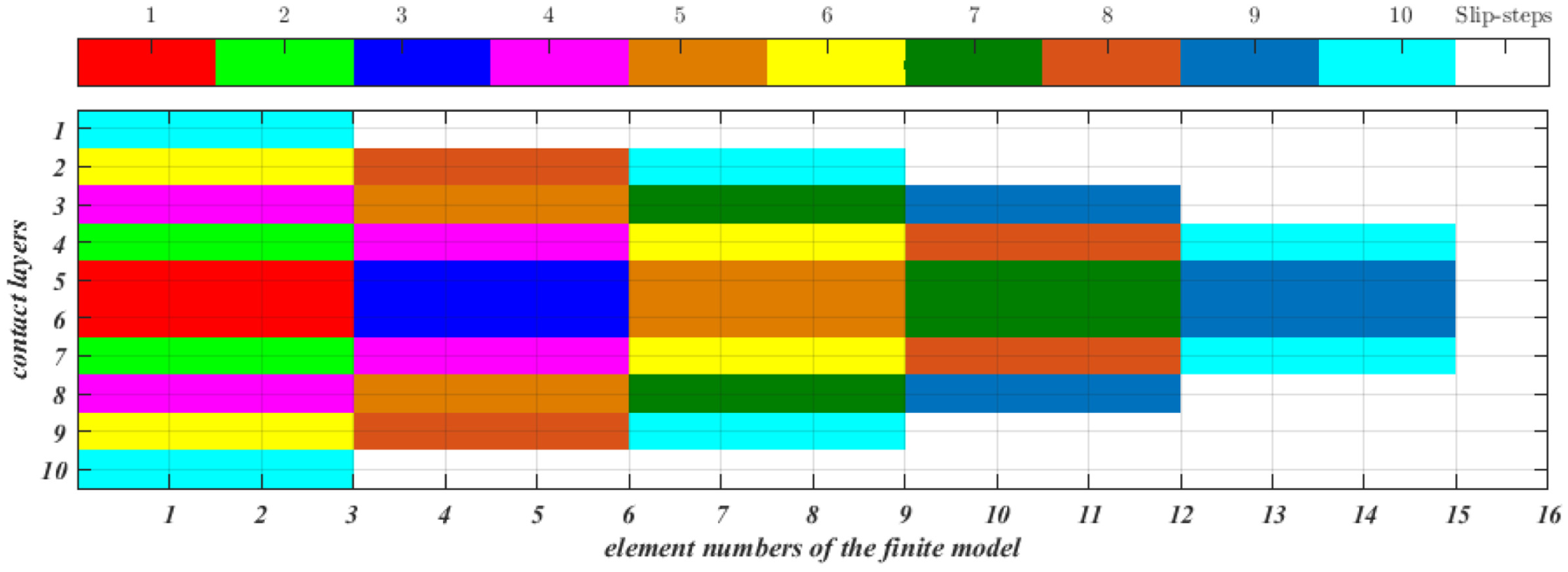
Slippage development process of contact layers in the laminated beam.
Displacement comparison in all substeps between FEM and the proposed algorithm is shown in Figure 13. It indicates that the proposed algorithm is still accurate and efficient in analyzing the mechanical characteristics of the laminated beam when considering interlayer slippage. FEM needs to adjust the iterative process manually. The proposed algorithm based on incremental superposition method automatically completes iterative calculation and seems to be simple and efficient.

Comparison of the displacement results in all substeps between FEM and presented program.
Figure 9 shows that the interlayer slippage reduces the stiffness of the laminated beam and increases the vertical displacement. The higher the proportion of slippage spread, the more significant the vertical displacement of the laminated beam is. Figure 14 shows the vertical displacement of midspan nodes with or without considering slippage in different substeps.
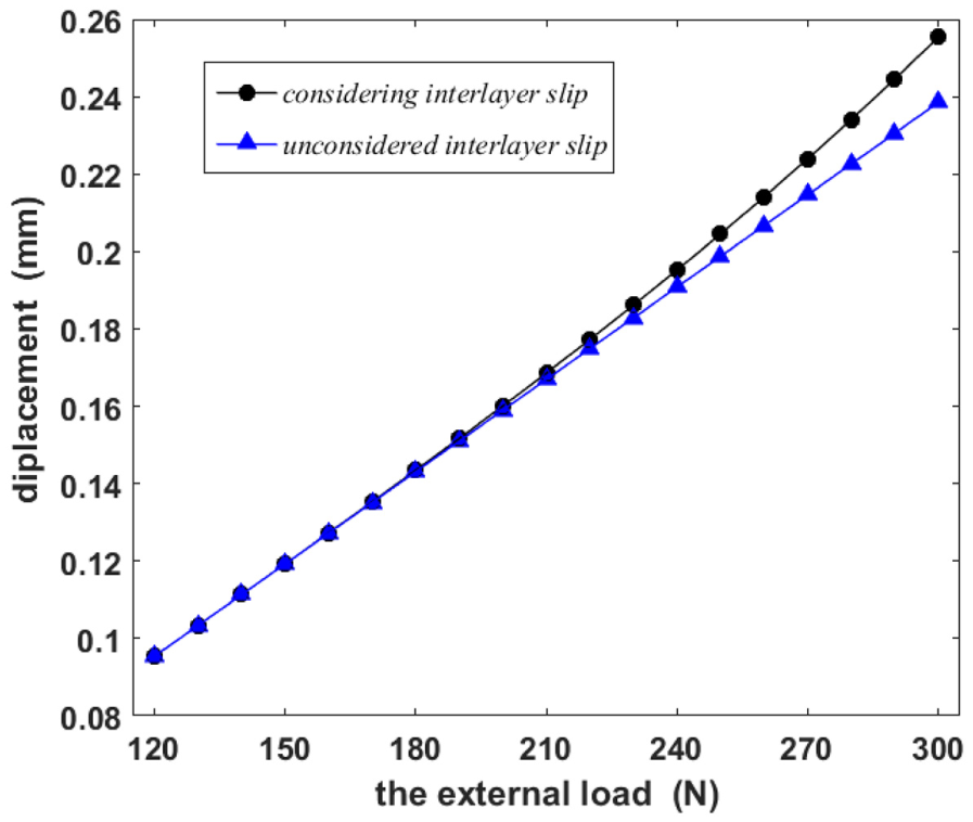
Variation curve of displacements for the middle node.
It can be seen from Figure 14 that for a beam without considering the slippage, the displacement and force are in a linear relationship because the axial force is assumed to be constant during the deformation, whereas for the beam taking the slippage into consideration, the displacement tends to increase non-linearly.
Conclusion
This article provides a mechanical analysis of the interlayer slippage in the contact layer of the frictional laminated beam based on the section analysis method. A new algorithm for calculating the slippage effect of laminated beam is proposed based on the incremental iterative recursive method and TMM. Comparisons against FEM numerical analysis results indicate that the present algorithm is accurate:
The interlayer slippage develops from the neutral axis to the outer layer symmetrically in the cross-section direction, and the interlayer slippage area in the longitudinal direction is related to the external loads applying position and the boundaries.
Interlayer slippage in the laminated beam will destroy the integrity of the section, thereby reducing the bending stiffness of the section and increasing the maximum bending stress. Therefore, even in the case of components mainly subjected to axial forces, the possibility of the components being subjected to lateral loads should be considered in structural strength design or fatigue calculation. If the components are subjected to lateral forces, the slippage effect needs to be considered according to the actual slippage effect of bending stress.
Future work
The continuation of this research will include the following:
Mechanical analysis of local bending behavior of the laminated beam by interlayer slip effect in different axial force conditions.
Better understanding of the effect of interlayer slip on the vibration characteristics of the frictional laminated beam.
Usage of the derivatives of eigen parameters method to identify the interlayer slip damage of the laminated beam.
Footnotes
Handling Editor: Ramon Serrano
Author note
Zhuojie Zhang is also affiliation to Innovation Center for Wind Engineering and Wind Energy Technology of Hebei Province, Shijiazhuang, China.
Declaration of conflicting interests
The author(s) declared no potential conflicts of interest with respect to the research, authorship, and/or publication of this article.
Funding
The author(s) disclosed receipt of the following financial support for the research, authorship, and/or publication of this article: J.Z. wishes to thank the support by the National Natural Science Foundation of China (grant nos 51478193 and 51678247).