
Abstract
This paper presents a state-of-the-art critical review of the thermal and structural modelling of the arc welding process. During the welding process, high temperature in the welding zone leads to generation of unwanted residual stresses and results in weld distortion. Measurement of the temperature distribution was a key issue and challenge in the past decade. Thermomechanical analysis is among the best-known techniques to simulate and investigate the temperature distribution, welding distortion and residual stresses in the weld zone. The main emphasis of this review is the thermal and structural modelling of welding processes and the measurement of welding residual stresses using different techniques. The study also provides information about the various types of heat sources and models used to predict the weld bead characteristics and thermomechanical analysis for different welding processes such as tungsten inert gas welding, metal inert gas welding and shielded metal arc welding.
Introduction
Welding overview
The process of joining metals with the help of heat and pressure using filler or without filler to produce coal essence is called welding. Welding is used to create permanent joints. It finds its use in many industries like shipbuilding, automobiles, oil and petroleum. In this process, electric current is used to create an arc between the electrode and the job, which heats the metal and melts it; this is known as arc welding. The electrodes used may be consumable or non-consumable. Flux is used to shield the weld metal from the gases present in the atmosphere. The process can be automated or manual. Arc welding, which was first developed in the 19th century, became commercially vital in the shipbuilding industry during the Second World War. Even today, it is a vital procedure in the production of steel pipelines and automobiles (Figure 1). 1
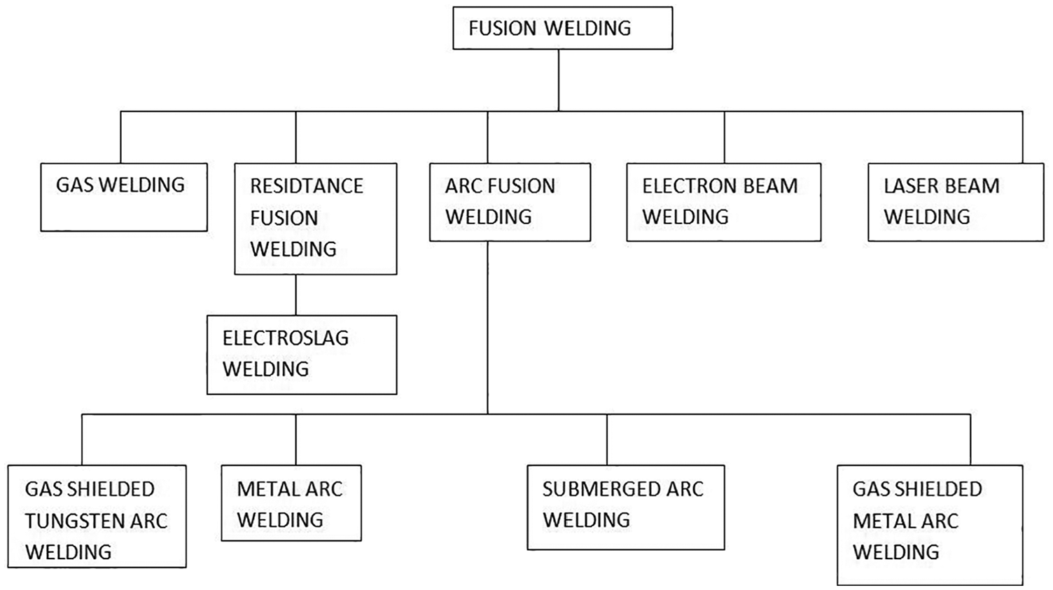
Classification of fusion welding processes.
Consumable electrode methods
Shielded metal arc welding
The most common, reliable and inexpensive welding process is the shielded arc welding process, also called the manual arc welding process. Here, the consumable electrode used is compatible with the material to be welded, which is covered with the flux. To strike an arc, the electrode is scratched with the workpiece and electric current is used. The electric arc melts the electrode and vapours off the flux, which protects the weld material from atmospheric contamination. The process uses inexpensive equipment and requires little operator training (Figure 2).2,3
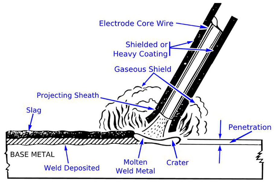
Shielded metal arc welding process.
Gas tungsten arc welding
This is a manual arc process in which a non-consumable electrode made of tungsten is used, with a separate filler and a mixture of gases for shielding purposes. This method is characterized by a stabilized arc and good weld quality, which is mainly used for the thin workpiece and requires great operator skills that can be done at low speeds. Stainless steel, aluminium and other light materials can be welded with this process (Figure 3). An allied process is known as plasma arc welding (PAW) in which the electrode used is also made of tungsten, but plasma gas is used to create the arc. The arc in PAW is more intense than the gas tungsten arc welding (GTAW) arc, restricting the method to a manufacturing process and also making transverse control more significant. One of the most important applications of the process is automated welding of stainless steel. Another variation of the PAW process is plasma cutting, which is one of the most efficient steel-cutting processes. 3
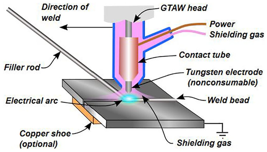
Gas tungsten arc welding process.
An important weld process required for the development and production of fusion reactor components is TIG welding. Various grades of stainless steel like SS 304, SS 316, SS 316L and some nuclear grade special materials with various thicknesses ranging from 2 to 60 mm are the major components developed for use in construction.
Metal inert gas welding
Metal inert gas (MIG) welding is an arc welding process in which a continuous solid wire electrode is fed through a welding gun and into the weld pool, joining the two base materials together. A shielding gas is also sent through the welding gun which protects the weld pool from contamination. Technically, it is called gas metal arc welding (GMAW), and the colloquial name for it is wire welding (Figure 4).
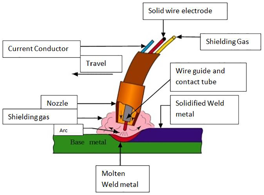
Metal inert gas welding process.
Other arc welding processes include electro gas welding, electro slag, atomic hydrogen welding, stud arc welding and carbon arc welding.
Welded joints
Welded joint types
Lap joint
This type of joint is made by overlapping the workpieces so that welding is done at the edges of the work material. The cross-section of the fillet is approximately triangular. Fillet joints are of three types: single transverse, double transverse and parallel (Figure 5).
Types of lap or fillet joints.
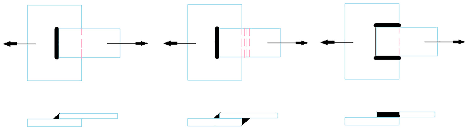
Butt joint
The butt joint is obtained by putting the two workpieces parallel, as shown in Figure 6. In butt welds, the plate edges do not require bevelling if the thickness of plate is less than 5 mm. However, if the plate thickness is more than 5–12.5 mm, the edges should be bevelled to V or U-groove on both the sides.
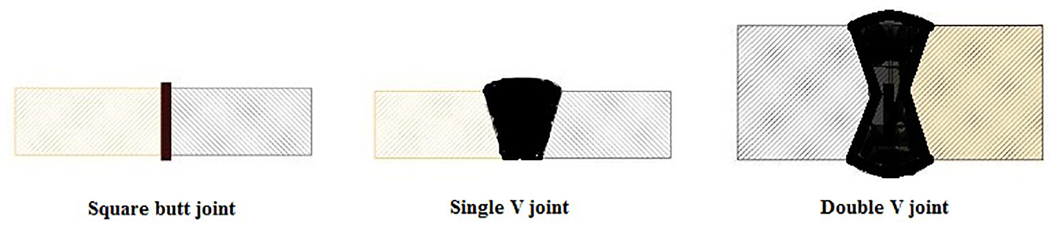
Types of butt joints.
The corner joint, edge joint and T-joint are some other types of welded joints, as shown in Figure 7.
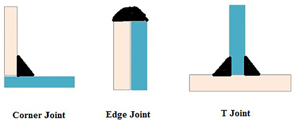
Types of other joints.
Welding heat flow
Considering the heat flow theory is vital in a way to learn the process of welding experimentally, analytical and numerically. Rosenthal was among the initial researchers to advance an analytic answer for the flow of heat. Rosenthal presented the moving coordinate system for Fourier equation of heat conduction to build up solutions for the line and point arc sources. He projected the shapes of the molten weld bead in two-dimensional (2D) and three-dimensional (3D) welding simulations. He executed the analytical study of the welding process to discover the influence of the welding parameters, namely voltage, current, weld geometry and welding speed. 4 Similar to Rosenthal, a number of researchers have shown significant concern in the thermal features of welding. 5
The parameters which are essential to depict the welding heat supply to the weld from the welding arc are the most crucial contribution data for thermal investigation of welding. Various mathematical models are proposed for different distributions of heat source in command to accurately arrest the shape and size of the welding heat source for better diffusion of heat into the welded joint. In this paper, a few welding heat source models from the literature are discoursed along with their application in welding simulation. Later, a review is given about appliance of the finite element (FE) process in welding process simulation.
Models of heat source
Circular disc heat source model
The circular disc heat source model, also called Gaussian heat source distribution, was proposed. 6 This model is based on Gaussian or normal distribution and is called the ‘circular disc’ model. The schematic of the heat source in 2D is given in Figures 8 and 9. The model is given as

Circular disc heat source.
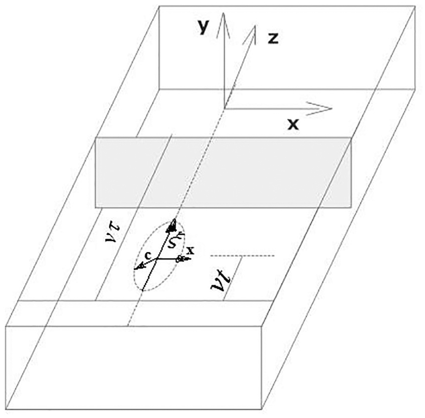
System of Cartesian coordinates for the movement of circular disc heat source model.
An option for the replacement of circular heat source model was given by Friedman and Krutz and Segerlind,7,8 who moved the heat source model in the welding direction as seen in the following equation
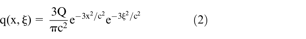
where q is the welding heat flux and c is the radius of the distribution of the heat flux.
The transformation relating the fixed coordinate system (x, y, z) and moving coordinate system (x, y, ξ) is given as

where
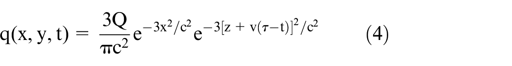
Equation 4 is applicable in the region, that is,
The surface heat source model of Pavelic et. al, Friedman and Krutz and Segerlind6–8 is successfully applied for welding simulations involving smaller depths of penetration. Andersson 9 applied the heat source model of equation (4) for the welding process simulation. To minimize the computational requirement of full 3D FE methods (FEM) analysis, he assumed that the heat flow in the z-direction is negligible, hence the heat flow is restricted to an x-y plane positioned at z = 0. He observed that this assumption results in insignificant error in temperature distribution except for low speed, high heat input welds. The disc moves along the surface of the workpiece in the z-direction and deposits heat on the reference plane as it crosses.
Double ellipsoidal power density heat distribution
Prior to the double ellipsoidal heat flux distribution, single ellipsoidal heat flux distribution was found by Goldak and Akhlaghi. 10 The former was not much accurate because heat distribution at the following border of the weld molten pool was rising and falling sharply than experimental dimensions, and in the front part, the heat distribution was not as sharp as expected. To rise above this drawback, 10 projected double ellipsoidal heat sources, in which there are two ellipsoids, one in front and the other is half, which gives the power distribution.
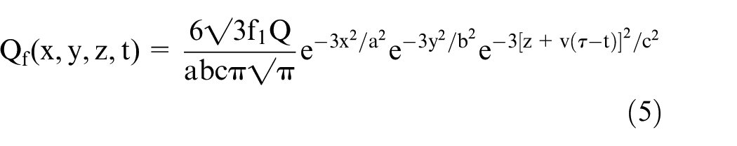
and for the rear half
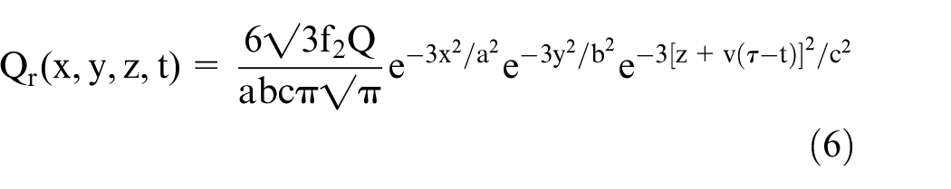
where
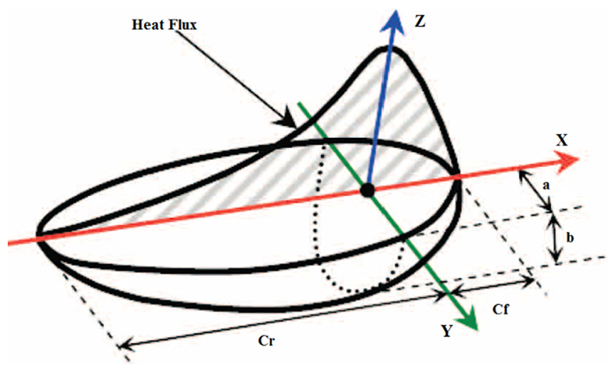
Configuration of double ellipsoidal heat source model.
Sometimes the weld cross-section may require a finer representation of the heat density distribution. For example, double ellipsoidal distribution may not be suitable to predict the weld pool shape given in Figure 11(b). Double ellipsoidal heat distribution approximates the weld pool shape given in Figure 11(a). Four ellipsoid quadrants could be superimposed to accurately prototype such weld pools given in Figure 11(b). A comparison of the single and double ellipsoidal models and the welding sequence models are shown in Figures 12 and 13, respectively.
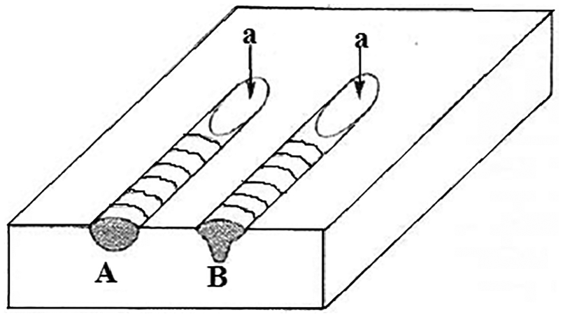
Sectional weld pool shape of the fusion zone.
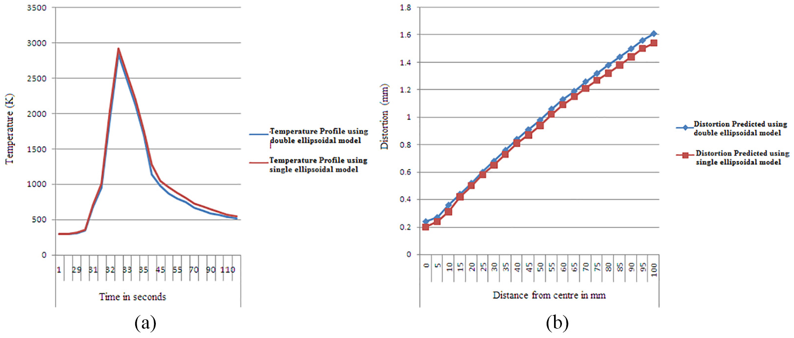
(a) Comparison of temperature distribution. (b) Comparison of angular distortion of double ellipsoidal model with single ellipsoidal model.
Welding sequence models.
The method for estimating the model parameters from the molten metal pool shape and size acquired from the molten pool surface ripple markings and metallographic data were proposed. 10 The sensitivity of the ellipsoid parameters to the temperature distribution was studied. It was found that the ellipsoidal parameters must be smaller than the molten metal pool size to provide accurate results. 11
Numerical solution
Standard heat transfer solution
Over the past few years, FEM are used extensively in a shot to predict residual stresses and distortion in welding operations. A guideline on the utilization of FE and boundary element methods for modelling and analysis of residual stresses is given by Mackerle. 12 The method to find the molten weld pool dimension was proposed by Wahab and Painter. 13 Using experimentation, they measured the weld pool dimension with the help of a mechanical device, by which the molten metal is ejected rapidly from the molten weld pool and reveals the immediate weld pool opening, which was grown for the subsequent FE modelling of gas metal arc (GMA) welding method. They established that the welding process parameters have great control on the dimensions of the weld molten pool. By increasing the welding current and speed, it yields a longer pool for constant heat input. Upper characters for all the dimensions of weld pool are yielded by increasing the heat input. 13 Trapezoidal deviation was used to model the heat distribution, which represents the movement of the welding heat source with constant heat input and pulling out of the heat source steadily. They stated that multi-passes give relief to the welding residual stresses, which was confirmed by the experimental measurements. 14 Demonstration of the welding heat source parameters, effect of heat density distribution on the heat affected zone (HAZ), fusion zone (FZ) and the profile of the weld bead was done by Gery et al., 15 who concluded that 3D analysis is preferable to 2D. In the weldment, various zones of the microstructure was approximated by means of the maximum temperature calculated with the help of the model and measured with the values measured experimentally of different zones of microstructure.16–22 The non-destructive capability of ultrasonic waves in evaluation of stresses of a welded circumferential joint of two different materials austenitic stainless steel, 304 and CS A106, was employed by Javadi et al. 23
Residual stresses and welding distortion
Welding stresses originate from the restrained welding distortion. Many research papers24–51 describe the models used to find the welding distortion and welding residual stresses. To get the exact model, the field describes the specimen of metal needed to be able to change its volume and shape; along with this, properties of the materials are required like specific heat, plasticity, Poisson’s ratio and density.
Comparison of temperature distribution and angular displacement with the experiments performed by Mahapatra et al. 27 showed good agreement. It was found that the double ellipsoidal heat source is preferable to the ellipsoidal heat source. 28
A study was conducted on the parameters which are directed for the effect of tacking on the resultant residual stress fields. It was concluded that axial residual stresses also depend on the different orientation of tack welds at an axial part
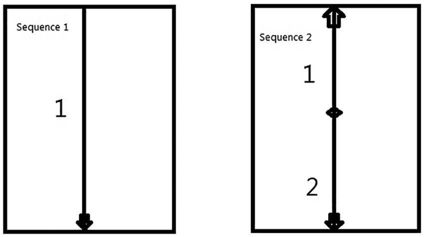
An efficient 3D welding simulation technique, the rapid-damping methodology, was developed to successfully apply the technique to the multi-pass size welded cylinder rib joint and to decrease the calculation time. Further examination on the 3D FE investigations is then required to systematically know the features of residual stresses in circumferential joints. Furthermore, the behaviour of welding induced residual stress underneath internal pressure; very less work is reported on this because of the complicated analysis followed by loading problems. Hence, intense interest is required on this, different FE approaches were implemented on a huge bogie beam structure. It was also established that the approach which used the minimum computational time among each of the methodologies is the quick dumping methodology which, furthermore, demonstrated subjectively great concurrence with the non-destructive X-ray diffraction method. Weld bead measurement value anticipated from the FEM give great concurrence with the test estimations and the computational time is essentially decreased by utilizing a sub-organizing approach with a satisfactory exactness of anticipated welding residual stress. 44 An FE model of multi-pass welding of huge tube sheets in command was offered to find the distortion induced in the tube hole. 45 They represented 2D FEM to calculate welding stresses and distortion on plate of grade stainless steel 400 metal. The outcome predicted from the FEA with the values of exploratory outcomes were compared, which gave decent agreement that the volume of heat input mainly depends on the welding process parameters, and welding prompted stresses and distortion are for the most part influenced with the sum of heat input in each welding pass. Mathematical study was done with the help of FE software ANSYS, for a welding of thick late with multi-pass GMA welding process. The deposition of metal for each welding pass is controlled by employing a birth and death technique. 46 Thermal-mechanical analysis was applied using FE methods, to examine the thermo elasto-plastic conduct and figure the welding stresses in welded joints. The welding stresses on the shell of the weldments were calculated with the help of non-destructive technique X-ray diffraction and the predicted results were matched with the predicted results from FEA to validate the process. 47 The result of clamp on distortions and stresses on thin plates of stainless steel of grade SS-304 in the single-pass butt welded joints were studied. Cases without and while clamping are studied, the welding stresses and distortion are foreseen by 3D FE simulation and matched with the data obtained through experimentation. 48 In this paper, 3D FEM for GTAW simulation for single-pass thin-walled circumferential weld has been presented. The distortion and residual stresses with welding joint configuration as single V joint with geometrical dimensions as outer diameter of 300mm and cylinder with 3mm thickness was calculated experimentally by strain gauges and FE examination utilizing ANSYS software was performed. 49 3D FE modelling, bearing in mind the transient welding source, was produced to imagine the temperature distribution, change in time 8/5 time, deformation and residual stress induced by Electro Slag Welding. 50 A 3D thermal-structural FE examination was used which assessed the weld instigated stresses in AISI 304L heat treated plates. FE representation was confirmed with the values obtained by the destructive experimental technique. The confirmed FE model was then matched with stress measurement using the ultrasonic testing machine. 51 The predicted after-effects of FE examination were compared with the values obtained from experimentation of bending initiated in a plate of stainless steel 304 with automated gas tungsten arc (GTA) welding process. 52 The temperature field at the top of the plate was found and was matched with FEA. Gaussian heat distribution and volumetric model was simulated and were experienced with two different welding velocities at 2.4 and 3 mm/s; the volumetric model is found to be less effectual than Gaussian heat source for the thin plates and the Gaussian heat source model obtained results were in conformity with the measured values. The effect of welding sequences on the temperature distribution and welding distortion of the butt welded steel plates were analysed using the FE method. 53 Thin plates having length of 500 mm, width 300 mm and thickness 4 mm of low carbon steel were welded with GTAW using two different sequences.
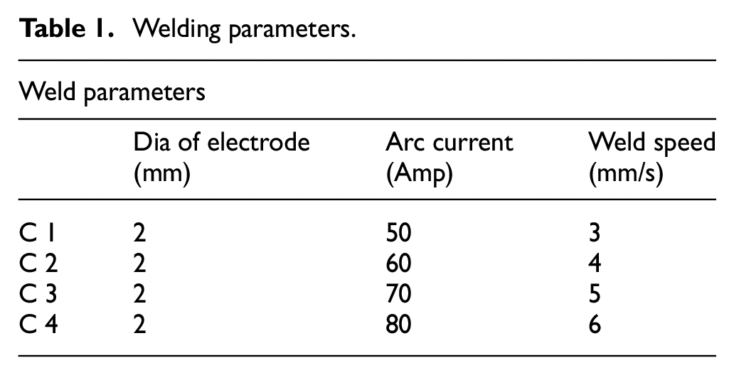
A comparison of the heat distribution of the sequences of welds 1 and 2 showed that sequence 1 yields high temperature, as a result of which greater deformation is expected. Using sequence 2, discontinuous welding, different properties of welded structure may be upgraded. Numerically investigation of the welding residual stresses and welding distortion of stiffened plates using and without using triangular brackets by a non-linear thermomechanical approach was carried out. The numerical results were validated with the experimental one and the results were found to be close; it was concluded that the bracket has less effect on the welding residual stresses in the plate and the utmost distortion in the stiff plate with two crosswise bracket decreases around ¾ in the values of experiment and around 67% in the numerical simulation. 54 Welding simulation of carbon steel plate was done using FE tool ANSYS and user subroutine, which achieved heat source application and addition of filler metal. The significant welding process parameters (Table 1) were also studied to find the effect on welding distortion. It was concluded that welding speed and distortion do not have a linear relation, as they had shown high amount of distortion at both low and high welding speeds (cases 1 and 4 respectively). 55 .
Welding parameters.
A model was developed to simulate the heat distribution and establish welding stress fields while welding a pipe. A pipe of SUS304 stainless steel was used. TIG welding two-pass with an inter-pass temperature of 50 °C was used. Thermal analysis was done using an 8-node brick thermal element. In the work, Goldak heat source model was accustomed for application of heat from the moving welding arc. Thermal radiation and convection heat transfer accounted for the heat loss on the weld surface. The investigation led to a total strain rate as

The code developed by Varma Prasada et al. 56 was validated with the investigational result presented by Deng and Murakawa. 57 Decent agreement was found between the predicted and experimental results.
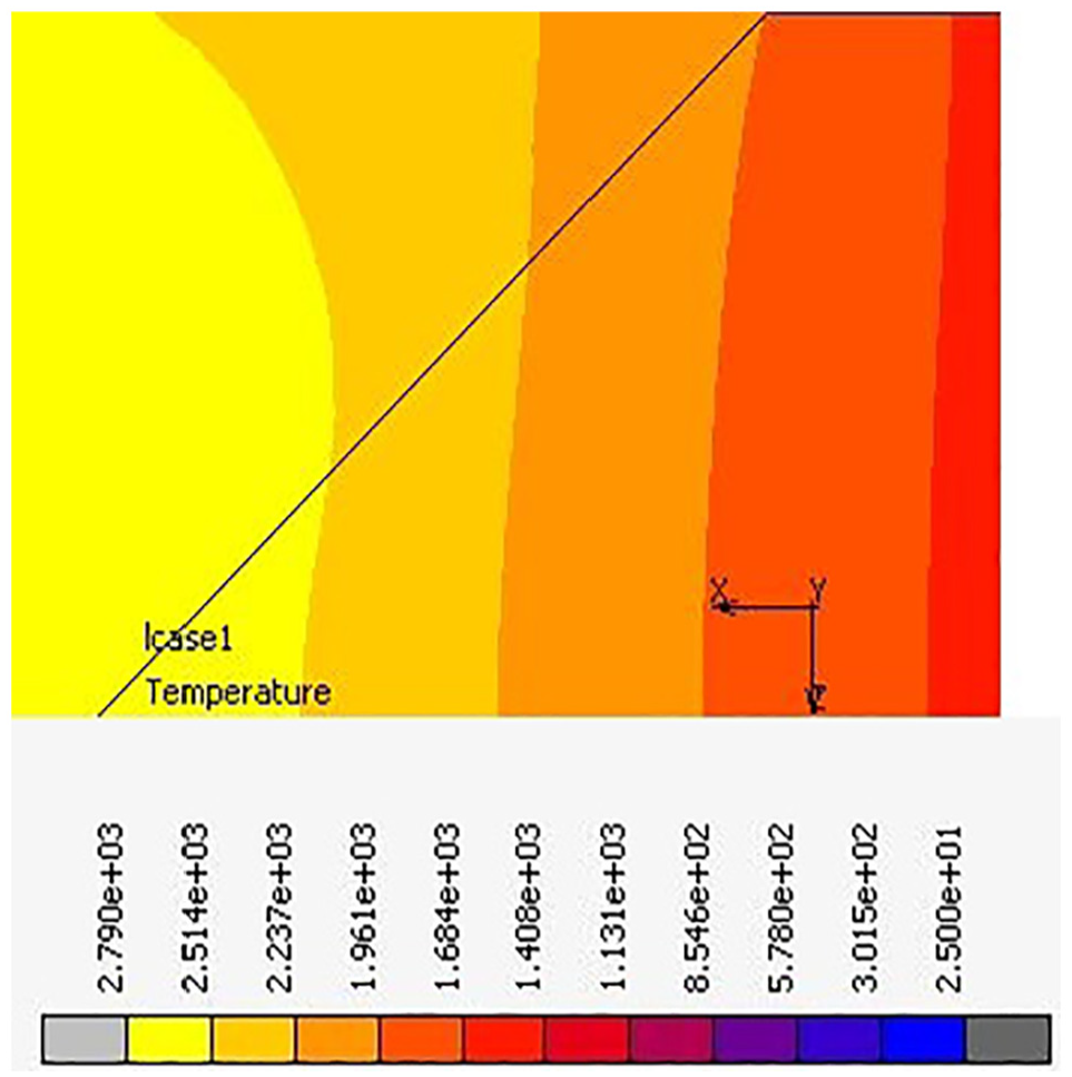
Numerical study on ANSI Flange class of 100 mm nominal diameter weldneck was done by Siddique et al. 58 Circumferential and transverse stresses were investigated by varying the diameter of pipe and the welding parameters, that is, welding speed and welding current. Serially coupled temperature-induced welding stress investigation method was employed to investigate the temperature distribution, stresses and distortion. The temperature distribution was calculated using moving thermal analysis. For distribution of the heat input, Goldak model was employed. Afterwards, prediction of the welding distortion and welding residual stresses of non-linear moving mechanical analysis was done. Simulation of depositing of molten filler metal was performed using birth and death element technique. It was concluded that at low welding speed, high-tensile circumferential stresses were found outside the HAZ and somewhat lesser tensile stresses were found within HAZ. With increase in the diameter of pipe, greater will be the stresses and the result of input of heat as shown in Figure 14(a) and (b).
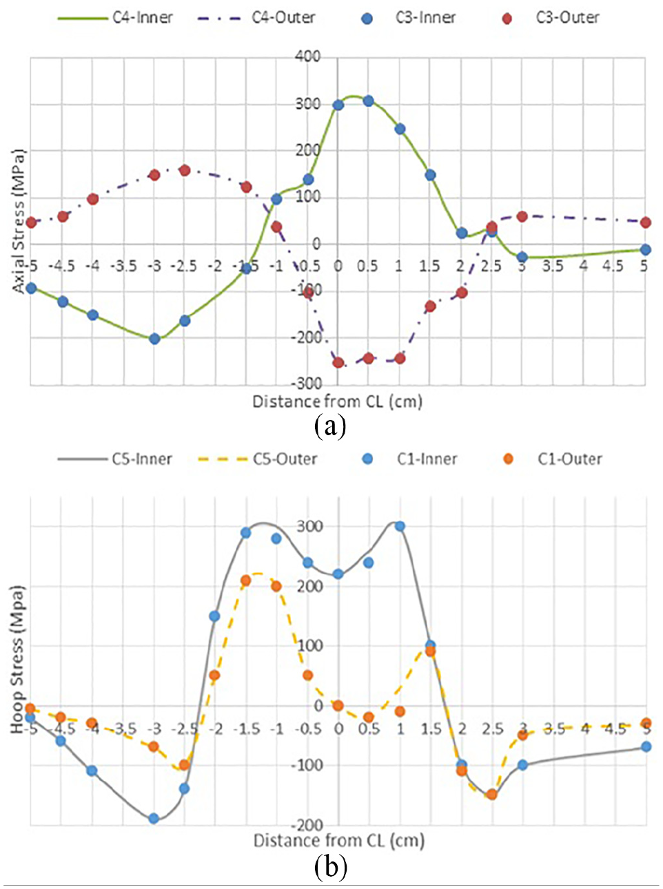
(a) Axial residual stress at Θ = 120°. (b) Hoop residual stress at Θ = 120°.
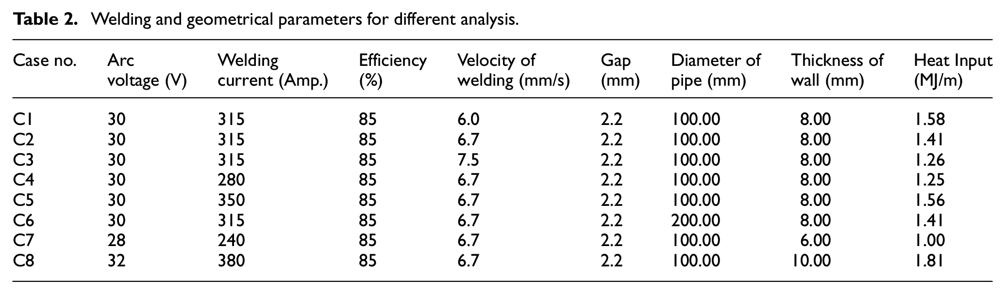
The development behaviour of residual stresses in the circumferential joints of stainless steel pipes was analysed. A 3D thermal-mechanical numerical model was created utilizing the MSC-Marc software to investigate the residual stresses in single-pass welding. Utilizing a numerical computational methodology, components of the adjustments in anxiety all through the pipe welding process are portrayed and the residual stress distributions in butt welded plates and pipe are compared. (Table 2). 59
Welding and geometrical parameters for different analysis.
A study on axi-symmetric 3D models was designed, and by employing the FEM residual stresses were calculated of pipe of material SAE 1020. The pipe was welded by choosing geometrical and welding parameters: pipe of schedule 5 and 10 were welded using current 110 A and voltage 20 V with different speeds of 0.5 and 0.58 cm/s, respectively. 20
It was found that the tensile stress decreases to zero at the weld line and then becomes compressive when it goes away from the weld centre line; the pipe with less wall thickness has less residual stress than the pipes having more thickness. Pipes of different thicknesses were welded at various welding velocities, with the high speed of welding the quantity of adjoining portion is less exaggerated by the heat of the arc. 31 It was found that weld induced stress and furthermore the welding contortion in low carbon steel does not appear to be affected by the solid-state stage change. Yet, for mild steel, the welding stresses and distortion appear to be extensively influenced by the martensitic change. The thermal field of joints made by submerged arc welding (SAW) process on plates was determined and the methodical solution for a transient different welding heat source was found considering different boundary conditions.60–62
The stresses in welded plates are examined numerically and experimentally. Moving FE model was created to evaluate the longitudinal stresses prompted by butt joint welding. Simulation of material deposition was done using technique element birth and death in commercial FE software ANSYS. 63
In thermal moving analysis, three passes were applied. Figure 15 shows the distribution of temperature at 10 mm from the weld bead.
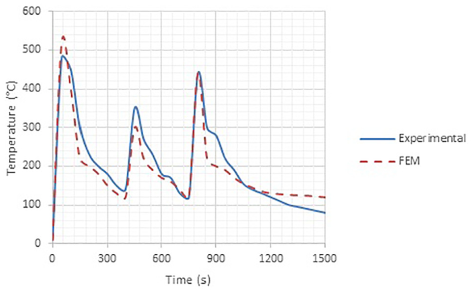
Temperature distribution, 10 mm distance from weld toe.
In every cycle, the time to cool is about 400 s. This gives a decent accord among the FE results and experimental results. The most extreme temperature happens in the main go because of the high heat input. The longitudinal stresses appropriation in the plate having width of 300 mm using trial and mathematical investigations is shown in Figure 16.
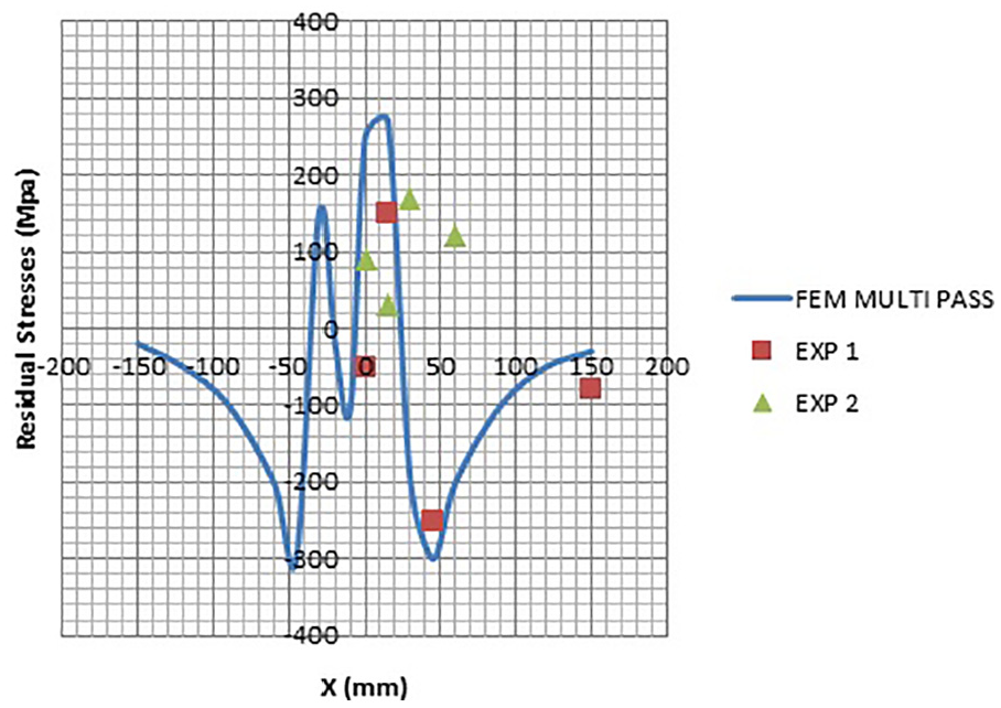
Stresses along axis at different locations.
Strain hardening models
The influence of different hardening models were studied, namely isotropic, kinematic and combined hardening was investigated for different ductile fracture criteria. 64 Ductile fracture criteria are also proposed by some researchers.65–69 Equations 1–6 were utilized in the kinematic hardening and the Lemaitre and Chaboche formulation with five constants has been utilized in the combined hardening models. 70 All of the criteria and models were applied to marketable FE software using user subroutines. The predicted effects of FE method was associated with the measured values for Nakazima tests to recognize the ductile fracture criterion (DFC) and the corresponding hardening model, which predict the fracture better in stainless steel material SS304L.71,72
Distribution of welding residual stress
There are many factors that upset the residual stress field in weldment modules. According to Leggatt, 73 the following are the reasons that concern the stress distribution in weldment parts:
The presence of residual stress before welding (manufacture and fabrication);
Material properties (weld and parent metal);
The geometry of the joined components;
Restrain applied;
Welding procedure;
Operation after welding.
Figure 17 shows the welding residual stress field. According to the figure the compressive stresses are present in the base metal only, whereas in the tensile residual stresses are also present in the HAZ and weld bead. This means that in the welded material both the stresses have compressive and tensile residual stresses. It was proved that steel influences residual stress. It is found that steel having less percentage of carbon (S15C) has a minor consequence on the (GTAW) residual stress, but the effect of medium carbon steel (S45C) on the residual stress is quite significant. 31 In this study, the researcher noted that the tensile stresses exist in the welded area, whereas the compressive stresses exist in the FZ. The stress field for the steel plates and steel pipes are different for both. Usually, a steel plate (Figure 17) welding yields tensile stress sited in the weld area, 74–79 while the compressive residual stresses are mostly found in the HAZ zone.75,77–79 However, the residual stress distribution in the steel pipes is different from the stress distribution in the steel plate. The presence of residual stress is established at the heat-affected zone of thick-walled stainless steel pipe of multi-pass narrow gap welding, but there is a difference in the distribution of residual stresses at the inner and outer surfaces of steel welded pipes. Compressive stresses are found near the outer surface of the weld area, whereas tensile stresses are found near the inner surface of the weld area. 80 The effects of joint geometry and welding parameters on the distribution and magnitude of stresses on butt joints thick welded section were examined. 81
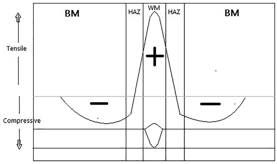
Welding residual stress distribution.
Research on stresses and thermal heat input in a welded structure was conducted by Monin et al. 82 The research concluded that the temperature influenced by the heat input of the effect on residual stresses is not linear. However, the use of smaller heat input is better to get lesser magnitude of residual stresses. Heat input does affect the distribution and value of residual stress.83,84 With the application of low input of heat, the compressive residual stress exists near to the weld bead of the components. Whereas with high heat input applied to the components, the component experiences tensile residual stress. This is agreeable, but it is also mentioned that heat input just has very little influence on the welding residual stress. 85
Investigation was done on the residual stress in steel plates induced due to multi-pass using the experimental and numerical methods. Axial residual stresses were estimated, which were produced by butt welding with the help of the developed FEM. FE software ANSYS was incorporated to simulate the welding process with the element birth and death technique. Plates with 6 mm thinness are modelled by one and three passes of welding to examine the effect on the stresses induced by the multi-pass welding. Experimentation was done to adjust the mathematical outcomes for each mechanical and thermal analysis. The X-ray diffraction technique was employed for measurement of stress. A decent conformity was attained among the experimental and numerical results. 86
Evaluation on the thermal distribution and stress during welding with the FE model was done by Deng and Murakawa. 57 Initially, a 3D model was evolved to replicate the thermal distribution and stresses in the steel pipe. Next, with the built character of the thermal and stress distribution, a 2D axi-symmetric model was also developed. The replicated result indicates that the 2D axi-symmetric representation can efficiently reproduce the temperature distribution and residual stress for SS pipe of SUS304. According to Deng and Murakawa 57 the use of 2D models can save a large amount of computational time.
Heat source parameters
Utilization of FEM recreation to examine the thermal–structural characteristics of DMR-249A steel welded joints produced by manual arc welding and actuated tungsten inert gas bend welding (A-TIG) forms were considered. The temperature appropriation and stresses were analysed down with SYSWELD programming and the utilized model was double ellipsoidal. 87
An affectability investigation of the proportion of back and face ellipsoidal factor (ar/af) on weld dimensions is delineated in Figure 18(a). 88
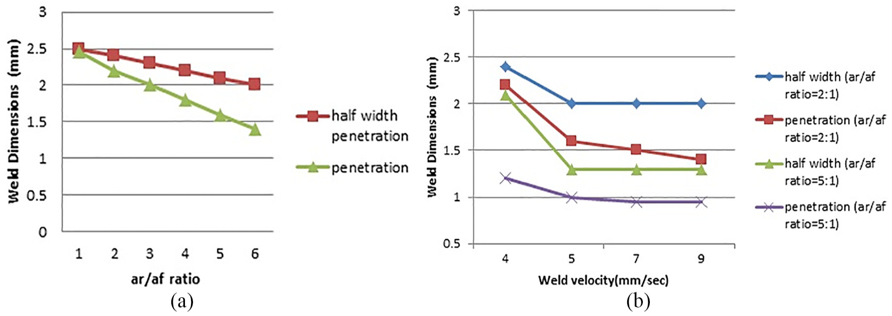
Sensitivity on weld dimensions. (a) (ar/af) ratio for data. (b) Weld velocity for (ar/af) = 2:1 (Yadaiah and Bag). 88
Figure 19 demonstrates the examination the weld macrograph (right side) tentatively estimated report (left side) relating to information and processed temperature.
Numerically and experimentally measured macrograph.
The great examination of test and processed weld measurements utilizing the ideal arrangement of ar/af proportion was found. It is known that a generally sensible understanding of the contour of figured thermal distribution support the right judgement of ar/af proportion in the reproduction of a straight welding procedure.
The link among the procedure factors and weld bead parameters is recognized to control the weld bead profile of the welded joint. Mathematical expression was developed to attain this, which is related to the key variables and the size of the weld bead upsetting these dimensions. The process parameters were also optimized to manage and get the quality of weld, which is also feasible using this mathematical expression. For attaining the desired weld bead dimensions, these developed numerical relations can be in use in automatic welding as a programme. 31
The peak current and pulse frequency has a greater effect on the dimensions of the weld bead, 89 developing the image processing algorithm to measure the weld pool geometry. The heat source model was confirmed with the results measuring the temperature distribution. MSC-Marc software was used, with which the temperature distribution was intended having double ellipsoidal model. The model results of the heat distribution and the weld pool dimensions are in decent concurrence with the measured results. 90 To control the weld molten pool dimensions, a combination of control algorithm, picture processing and sensor are employed. Different experiments were performed for initial parameters heat transfer condition change and torch speed variation. Using the proposed sensing technique, a control system was developed. Robust adaptive control algorithm was developed to acquire high control performance and to control the pool area. 91 A method to estimate the heat source parameters, which combines analytical formulation, experimental data and numerical simulation, was suggested by Chujutalli and Estefen. 92 Facchinotti analytical formulation is employed to determine isotherms in the space where peak temperature values and weld bead size are obtained for an isotherm associated with the base material’s melting temperature. Experimental data of the welding process and the bead weld size are input data in the algorithm. A numerical model has been established for the calibration and validation of the model. The parameters obtained by the proposed method are validated by correlating the numerical and experimental results from tests of a single weld bead, showing good agreement. The numerical analysis model of the 3D transient welding thermal process of GTAW welding stainless steel 10Cr18Ni9 thin plate, was established, based on the Goldak heat source model. The method for determining the arc distribution parameters by the calibration tool of SYSWELD software is given. The FE result of the molten pool is compared with the results of the experiment, and the effects are in high-quality concurrence with the measured results. 93 The contour of the molten weld pool and thermal gradient are obtained for a variety of welding processes with the help of the analytical method. By employing the neural-network programme, the heat source parameters are forecast. The final results of molten weld pool size and temperature obtained by the mathematical simulation using predicted factors of heat source are validated by the measured results, which are already published. 94 The composite light filter is combined with a commercial charge coupled device (CCD) camera to frame a low-cost vision sensing arrangement. The entire image of a weld pool can be captured using CCD clearly during constant-current (GTAW). The edges of the weld pool can be extracted based on the image processing algorithm, under different welding conditions.95,96
Outlook
An abundant comprehension of the performance of the arc welded joints is important to guarantee the well-being, effectiveness and consistency of such joints. Numerical investigations of the arc welding processes can give sensible estimation of the principle factors of the procedure. This decreases the cost of optimizing the variables; speeds up the design processes and lessens the quantity of exploratory tests. However, many necessary key issues and problems are yet to be addressed. Significant residual stress and distortion are regularly created by the arc welding process, preventive mechanical usage. The capacity to precisely anticipate residual stresses and furthermore the resultant distortion is a key item from simulations of assembly processes.
The literature survey outcome is as follows:
The residual stress pattern in the case of plate is totally different from the pattern of residual stresses in welded pipes.
The axial residual stress is compressive on the outer surface and tensile on the inner surface near the weld line. Tensile axial residual stresses are formed on the outer surface, away from the weld centerline, and compressive axial residual stresses are formed on the inner surface in the case of circumferential joint.
Transverse residual stress is tensile on the upper side and compressive on the lower side at the middle position of weld line in the case of the plate butt joint.
There is little effect of the mechanical constraint on the residual stresses.
Literature surveys regarding the simulation of arc welding process show that an important amount of work has been reported on the 2D and 3D temperature distribution. Most researchers have concentrated on welding deformation and residual stresses in plates. Furthermore, certain aspects of welding phenomenon are still the subject of research, specifically effects of welding speed, heat input, restraint and arc gap on temperature distribution, distortion and residual stress field distribution for welded pipe joints.
Footnotes
Appendix 1
Acknowledgements
The authors are thankful to IKGPTU Jalandhar and GNDEC Ludhiana for technical support.
Declaration of conflicting interests
The author(s) declared no potential conflicts of interest with respect to the research, authorship and/or publication of this article.
Funding
The author(s) received no financial support for the research, authorship and/or publication of this article.