
Abstract
A long-travel positioning device, which combines a ball-screw-driven coarse stage with a fine one, driven by piezoelectric translator, to achieve the long-distance traveling, up to 500 mm, as well as high-precision positioning, is crucial in the field of diffraction grating fabrication at nanometer scale. In this article, we present the design of the fine-feed drive stage with resolution as high as 20 nm and propose a single neuron-based proportional–integral–derivative controller to realize ultra-precision positioning. A high-performance piezoelectric translator is used to drive the mechanism, and the parallel leaf springs are used to guide the moving platform with preload force. A dynamic model of the precision positioning mechanism has been established by considering the Hertzian contact. In addition, the static and dynamic properties are investigated with the laser interferometry tracking methodology. The experimental results indicate that the positioning accuracy of less than 10 nm is obtained with the single neuron-based proportional–integral–derivative controller and also demonstrate the excellent performance of the proposed mechanism and control strategy.
Introduction
Recently, ultra-precision positioning techniques have become one of the most important features of an ultra-precision machine.1,2 They are widely used in various industrial applications, for example, machine processes, computer components, scanning probe microscope, biotechnology, integrated circuit manufacturing, optical docking, and robotics, especially in the area of diffraction grating manufacturing.3,4 The demand for gratings with a larger ruled area and higher groove density has increased remarkably because of the rapid development of synchrotron radiation and space astronomy, and the requirement for high-quality spectrometers. 5 Due to its deep-groove and high-groove profile accuracy, the echelles and large area gratings can only be manufactured by mechanical means. In contrast to holographic fabrication, the grating is shaped through extrude and polished on the aluminum film of the grating blank using diamond blade. 6 Based on universal measuring machines manufactured by Moore Company, Richardson Laboratory developed MIT-Band and MIT-C grating marking machines in 1961 and 1966. These two marking machines have carved high-precision diffraction gratings including echelon gratings.
For a diffraction grating ruling engine, better system stability, rapid dynamic response, long motion stroke, and high-precision positioning are required. The optical performance index of diffraction grating, such as stray light intensity and wave-front quality, is closely related to the groove straightness, which is determined by the location accuracy of the positioning stage. The final shape of diffraction grating, such as the spacing uniformity, often depends on the vibration performance during the precision positioning process. In other words, the relative position of the precision blank carriage must be accurately controlled to achieve the desired processing quality. Generally, the traditional mechanical infeed mechanisms suffer from shortcomings, such as backlash, stick-slip, dead zone, friction, and large inertia, which are difficult to implement in nanometer machining without special designs.2,7 To address these critical issues, a dual positioning system is developed, combining coarse (large stroke) and fine (high resolution) stages. Based on the design concept, an auxiliary precision mechanism, which works together with the conventional ball-screw infeed mechanism, is proposed to achieve nanometer scale infeed.
A lot of recent works have been focused on the mechanical design of nano-positioning systems. Wu et al. 8 developed a linear active disturbance rejection controller design for a voice coil motor-driven fast tool servo system for noncircular machining application and the controller is designed through an extended state observer to estimate and compensate the variant dynamics of the system, nonlinearly variable cutting load, and other uncertainties. Based on the integral-type sliding mode control (SMC) law, Chen et al. 9 proposed two sets of controllers corresponding to the static and the dynamic friction models and the experimental results demonstrated that the system achieves high-precision (10 nm) and long-range (10 cm) positioning performance with repeatability and robustness. For a precision positioning planar motion stage, Dejima et al. 10 discussed the dynamic modeling, controller design, and experimental validation, and the experimental results indicated that the developed controller provides fast positioning with less tracking error than a simple proportional–integral–derivative (PID) controller and is suitable for precise positioning of multiple degree-of-freedom (DOF) stage system. Chu and Fan 11 developed a novel long-travel piezoelectric-driven linear nano-positioning stage which can be operated in either a stepping mode or a scanning mode; in the stepping mode, the stage is capable of performing precision positioning over an extended displacement range in incremental step sizes ranging from 70 nm to 35 µm, and in the scanning mode, the stage can perform a scanning motion over a displacement range of 50 µm with a displacement resolution of less than 10 nm. Tian et al. 12 presented the dynamic modeling and performance evaluation methodologies of a flexure-based mechanism for ultra-precision grinding operation, which includes a piezoelectric actuator used to drive the moving platform and a flexure-based structure used to guide the moving platform and provide preload for the piezoelectric actuator. Yao et al. 13 reported on a novel piezo-driven, parallel-kinematic, micropositioning XY stage which comprised parallelogram four-bar linkages, flexure hinges, and piezoelectric actuators, and linear and circular contouring performance in closed-loop mode suggests high scanning performance for such parallel-kinematic stages.
In particular, the implementation of compliant joints has drawn much attention.14,15 These types of joints have several advantages, including free of backlash, zero friction, and negligible hysteresis. 12 Besides, piezoelectric translators are used to generate continuous expansion motions with large driving force, infinite resolution, high static and dynamic stiffness, and high response frequency. Therefore, the mechanisms have the advantages of smooth and repeatable motion with negligible friction, nanometer resolution, and free of thermal heat generation. They represent the best choice for a secondary infeed mechanism for nano-precision positioning applications. 16 To improve the performance of the piezo-driven mechanism, lot of control methodologies including PID control, BP neural network control, and robust control have been investigated. Meanwhile, an accurate dynamic model for the mechanism is of great importance to the proposed controllers. Therefore, these techniques and strategies will be helpful for the design and construction of the ultra-precision positioning system with high dynamic performance and resolutions.17–19
The rest of the article is organized as follows. First, the mechanical design of the precision feeding mechanism is mainly described. The piezoelectric translator and beam-based flexure joints (leaf springs) are adopted to improve the performance of the mechanism. Then, the finite element analysis (FEA) is considered in the design process, as a tool for predicting the behavior of the mechanism. Finally, the dynamic model of the fine positioning mechanism is developed, considering the driving circuit effect. Experiments are also carried out to test the models and examine the performance of the developed piezoelectric-driven flexure-based mechanism.
Nano-precision feeding mechanism
Design of the piezoelectric-driven flexure-based mechanism
Figure 1 shows the photograph and the schematic diagram of the dual-drive positioning system of the grating ruling engine. The fine system and the coarse one will work together in complementary ways to achieve the maximum effect. The coarse-feed drive stage (CFDS), driven by the traditional ball screw, is improved to expand the travel range (the stroke is set to be as long as 500 mm), while the fine-feed drive stage (FFDS) is applied to obtain high positioning accuracy. In the coarse process, the CFDS is driven by the servo motor through worm gearing and screw–nut pairs. After traveling a certain angle over the grating constant, the motor will get locked. Because of the long drive chain, the whole stage needs a short time for adjustment. Then, FFDS gets to the predetermined point. The intermittent positioning strategy of dual-drive system is shown in Figure 2. The particular design of the FFDS meets Abbe’s principle of alignment, where a piezoelectric translator is fixed to the CFDS and located against the FFDS. Since the grating blanks were placed on the FFDS, the main focus of this study is the design of the FFDS referring to the flexure-based mechanism.
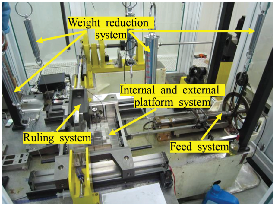
Prototype of the dual-drive positioning system.

Intermittent positioning of dual-drive system.
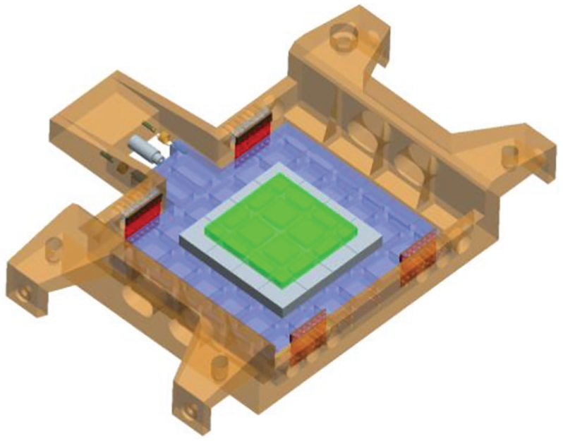
The FFDS is connected to the CFDS through two pairs of parallel leaf springs. The joints provide both a lateral guideway for the moving platform and a spring preload for the piezoelectric translator. The dimensions of the leaf springs greatly influence the characteristics of the piezoelectric-driven flexure-based mechanism. The geometric accuracy should be ensured during the manufacture process, while the leaf springs can be changed with different elastic coefficient according to the mass of the grating blank. The details of the assembly of the FFDS are shown in Figure 3, which also reveals how the mechanism works.

Positioning process of the system.
To achieve the balance between the working range and the contact condition, the topological shape and geometric parameters are optimized, which is shown in Figure 4. Moreover, FEA using Pro/Mechanica (Parametric Technology Corporation) is also introduced to analyze the dynamic and static characteristics of the design of the positioning mechanism. The material of the leaf springs is 65 Mn and the mass is 1.68e−2 kg. The dimension of the leaf spring is 0.5 × 70 × 64.5 mm3. The radius of the circular hole is 4.5 mm; the distance between the two leaf springs on the same side is 150 mm. Figure 5 illustrates the mechanical property of the flexure joints obtained from the Pro/E FEA and experimental tests. The results show that the deformation of the leaf springs is proportional to the drive force. With the increase in applied force, the deformation of leaf spring increases in equal proportion and the difference between the experimental and simulation results also increases.
Structure of the leaf spring.

Mechanical characteristics of the spring lamination.
To get large stroke, high stiffness, and continuous drive load, stacked translators are employed. Due to the brittle character, the translator can withstand significant amount of compressive stress, but it cannot suffer against shear force and is easy to be damaged from lateral force. To overcome this shortcoming, the piezoelectric translator is loosely connected to the moving platform, and a ball-tip mounting mechanism is added between the piezoelectric translator and the platform, which appears to be the Hertzian contact. Thus, the appropriate preload is necessary to guarantee the required contact condition in case of separation between the two parts when the piezoelectric translator retracts rapidly because of its high dynamic response characteristics. Two springs are mounted on the two sides of the FFDS to generate a preload on the moving platform to ensure the retraction. In this way, the platform can traverse back and forth following the piezoelectric translator in a certain range. Note that the stiffness of the preload springs should not be too high to avoid the obvious reduction in the actual working range and large deformation. However, the contact condition might be affected if the stiffness is too low.
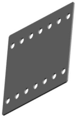
The principal criterion of the moving platform design is a high natural frequency in the positioning direction. The mass of the FFDS is minimized to achieve a wider range of operation frequencies. Meanwhile, the reduction in the mass cannot significantly affect the rigidity of the mechanism. The moving platform carrying the grating blanks is set to be 600 × 500 × 200 mm3, which is made of steel and contains several location holes to fix the blanks.
The PAHL series of translators are ideal for high loads. They reach high blocking forces and can move large mass. In addition, they can work under tensile forces dynamically due to the integrated mechanical preload. Therefore, a PAHL 120/20 piezoelectric translator, from the Piezosystem Jena Company, has been chosen. The piezoelectric translator is able to generate a displacement up to 120 μm under the preload of 350 N. Since the resonance frequency of the piezoelectric translator is 5 KHz, it can be used in high dynamic environment. The rigidity of the translator is approximately 30 N/μm. As a result, it can bear a high load up to 3500 N. The performance parameters of the piezoelectric translator are listed in Table 1. A piezoelectric-driven circuit is also used to supply control voltage for the expansion of the piezoelectric translator. Because piezoelectric ceramic material suffers from typical hysteresis nonlinearity, the output of the piezoelectric translator is determined by the current input voltage and the previous one. The closed-loop controller can efficiently remove the hysteresis nonlinear error and ensure high-frequency response.
Performance parameters of the piezoelectric translator.

Model testing of the piezoelectric-driven flexure-based mechanism
As mentioned above, the first natural frequency of the designed mechanism is expected to be far apart from the machine operation frequency range. Modal analysis is performed to determine the natural frequencies, mode shapes, and frequency constraints of the structure. Figure 6 presents the virtual prototype of the FFDS prepared for the FEA.
Virtual prototype of the fine-feed drive stage.
Since the high-frequency modes decay rapidly, the former 10-order modes and their model shapes were extracted. Table 2 lists the mode parameters of the FFDS and FMS and CMS denote fine mechanical stage and coarse mechanical stage. The results show that the lowest natural frequency, that is, 27.4 Hz, performs along the feed direction. In the low-frequency range of 0–300 Hz, four vibration modes emerge and the first low-frequency vibration mode of FFDS is excited. This indicates that the configuration of designed mechanism is insensitive to the perturbation, and the isolation platform can reduce the signals in high-frequency range, far above 30 Hz.
First 10 natural performance of the mechanism.

CMS: coarse mechanical stage; FMS: fine mechanical stage.
The impact modal test is also performed to verify the dynamic performance of the precision positioning mechanism. The signal with swept frequency was generated in the signal generator and applied to the moving platform of the flexure-based mechanism through the piezoelectric translator. The impact force is exerted on one side of the FFDS and the displacement along the feed orientation can be measured to obtain the frequency response function (FRF). The magnitude of the FRF of the system is described in Figure 7. Note that the primary axial natural frequency can reach up to 220 Hz, as shown in the figure.
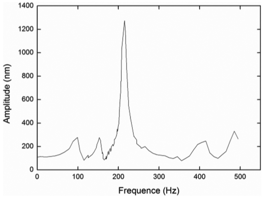
Frequency response function of the designed mechanism.
Dynamic modeling of the mechanism
To investigate the dynamic characteristics of the established mechanism, the schematic mechanical model is developed. The whole system is modeled as a lumped parameter. Constructed from multiple piezoceramic elements, the piezoelectric translator can be taken as a capacitive component. Meanwhile, considering dynamic performance of the piezoelectric translator during charging and discharging, the translator can be equivalent to a mass–spring system with a damping coefficient cpzt. The four leaf springs are connected to the CFDS. Compared to the mass of the moving platform, their inertia can be neglected. The stiffness of the flexure joints can be regarded as a spring on the moving platform. According to the Kelvin model, the Hertzian contact between the piezoelectric translator and the moving platform can be taken as a linear spring in conjunction with a linear damper. 20 The dynamic model of the mechanism is shown in Figure 8, where Fpzt is the driving force generated by the piezoelectric translator, Fpre is the preload force, and ms is the equivalent mass of the moving parts.

Dynamic model of the designed mechanism.
According to Kirchhoff’s law, the following equation can be obtained

where the value of RC is the time constant of the equivalent circuit, vpzt is the actual voltage applied to the piezoelectric translator, vd is the command signal, and kamp is the amplifier constant.
However, y0pzt of the piezoelectric translator is as follows

where n is the number of layers in the piezoelectric translator and d33 is the piezoelectric constant.
When it is in the force equilibrium, the displacement of the piezoelectric translator is

where kls is the equivalent stiffness of two leaf springs in pairs, kpzt is the stiffness of the piezoelectric translator, and kh is the generalized stiffness parameter of Hertzian contact.
Considering the compression and stiffness effect of the mechanism and the piezoelectric translator, the transient force generated by the expansion of the piezoelectric translator is calculated as follows

From Newton’s second law of motion, force, and acceleration of the preload springs, the differential equation for dynamic motion of the piezoelectric-driven flexure-based mechanism is given as follows

where
The main parameters of the proposed dual-drive positioning system obtained by the method of system identification with experimental data are shown in Table 3.
Main parameters of the proposed dual-drive positioning system.

Experimental testing
To maintain the nano-precision positioning and validate the performance of the feeding mechanism, a series of experiments have been carried out. The laser-based interferometry tracking methodology 21 is chosen for dynamic high-accuracy displacement measurements due to its advantages of strong anti-interference ability, low measurement uncertainties, and high accuracy and resolution. The schematic diagram of the measuring system is shown in Figure 9. The measure plane mirror is fixed to the moving stage, while the reference plane mirror is set motionless on the pedestal. In this study, a laser-based measurement system with a resolution of 0.15 nm and an update rate of 20 MHz is used. The apparatus consists of HP Agilent 10715A differential interferometer, N1231B laser board, E1709A remote high-performance receiver, and 10717A wavelength tracker. To reduce external vibration disturbance, the experiments are conducted on a vibration-isolated platform. Figure 10 shows the vibration caused by the remaining noise after isolation, and the amplitude is around 10 nm.

Schematic diagram of the measuring system.

Environmental noise level of the test system.
For a precise positioning mechanism, the resolution is one of the main goals for the high performance. Ideally, the piezoelectric translator can get high resolution; however, it can be reduced by the background noise and uncertainty of the measurements. As shown in Figure 11, the resolution of the mechanism is 20 nm. The asymmetric shape of the curve is mainly caused by the hysteresis of the piezoelectric translator, which can be reduced under closed-loop control condition.

Resolution of the designed mechanism.
To investigate the positioning quality of the designed mechanism, a square command signal was applied to the piezoelectric drive amplifier. The responses of the mechanism are shown in Figure 12. Figure 13 represents the open-loop open response of the positioning mechanism.

Response of the designed mechanism to square command signal.

500 nm open-loop positioning response of FFDS.
Apparently, during the positioning process, the overshoot phenomenon appears. The overshoot becomes larger as the command signals increase. The unexpected overshoot might spoil the grating blank and lead to poor ruling quality. To improve the performance, the closed-loop control strategy as the single neuron-based PID controller was used, whose schematic diagram is shown in Figure 14. The features of the PID controller include simple calculation, strong robustness, and easy realization. By combining a simple network with only one neuron, the calculation gets simple and effective.

Schematic diagram of the single neuron-based PID controller.
Figures 15 and 16 represent the step response performance to the command signal. As shown in the figures, the moving stage rapidly moves from the initial position to the pre-designated position in 560 ms, and the three-sigma value of the deviations is 8.71 nm. As a result, the proposed method using single neuron-based PID control can effectively restrain the overshoot and get high positioning accuracy.

500 nm closed-loop positioning response of FFDS.

Steady error of 500 nm positioning response using PID control with single neuron.
The aim of the nano-positioning mechanism is to carry the grating blank and to accomplish the diffraction grating fabrication in conjunction with the scratch system. Being part of the diffraction grating ruling engine, the operation of the scratch system and the grating fabrication will lead to other unexpected vibrations. Therefore, the study on the location accuracy under the whole machine running condition turns out to be particularly important. Considering the vibration mainly induced by the scratch system, to verify the performance of the mechanism, we carried out some grating fabrication experiments when the whole ruling engine works. As mentioned above, the PID control with single neuron was chosen, and the groove density was 79 g/mm, suggesting that the grating constant was 12658.23 nm.
Figure 17 shows the location curve of the designed mechanism under ruling operation. The results imply that the rigidity of the coarse stage gets worse, while the whole stage still moves forward after the servo motor stops. This is probably caused by the structure defects. However, with the help of the developed mechanism, the location error caused by outside interference can be compensated immediately. In Figure 18, 10 grooves were extracted, and the three-sigma values of the deviations of grooves are 7.1–8.7 nm, suggesting that the designed piezoelectric-driven flexure-based mechanism can acquire good localization effect.

Position result under 79 g/mm grating fabrication.

Three-sigma values of the 20 groove deviations.
Conclusion
In this article, the dual-stage actuation concept has been adopted to simultaneously provide a long motion stroke, high resolution, and high location accuracy. A piezoelectric-driven positioning mechanism with parallel flexure hinge has been presented in detail for the diffraction grating ruling engine. FEA is also performed to the design procedure. The dynamic model of the FFDS has been established considering the Hertzian contact. To circumvent the overshoot problem during the open-loop positioning process, the PID control approach with single neuron was applied to guarantee the positioning accuracy.
By employing the laser interferometer to collect the positioning data, the result shows that the closed-loop control can significantly eliminate the overshoot and improve the dynamic performance of the mechanism. It is found that the whole feed system can maintain a long travel range (over 500 mm). The response time reaches less than 1000 ms, the resolution of the mechanism is better than 20 nm, and the steady positioning error is limited to 10 nm. Consequently, the designed mechanism can be applied in the field of grating manufacture and satisfy the need of the diffraction grating ruling engine with 6000 g/mm groove density.
Footnotes
Handling Editor: Shahin Khoddam
Author’s Note
Biao Chu is also affiliated with Department of Precision Machinery and Precision Instrumentation, University of Science and Technology of China, China.
Declaration of conflicting interests
The author(s) declared no potential conflicts of interest with respect to the research, authorship, and/or publication of this article.
Funding
The author(s) disclosed receipt of the following financial support for the research, authorship, and/or publication of this article: This research work was supported by the National Natural Science Foundation of China (grant no. 51705117) and the National Program on Key Basic Research Project of China (grant no. 2014CB049500).