
Abstract
To study the effects of joint clearance on the dynamic characteristics of the momentum wheel assembly of satellite antennas, the computational dynamic model of momentum wheel assembly is developed in this article, considering influencing factors including rotor imbalance, flexibility, and joint clearance between rotor and bearing. The nonlinear contact force model and modified Coulomb’s friction model are adopted in the joint clearance of the dynamic model, and then the influence of clearance size, driving angular velocity, and friction coefficient on the dynamic behaviors of momentum wheel assembly is further analyzed. The results indicate that the existence of joint clearance has extraordinary obvious effects on the dynamic system characteristics, which causes the adjusting time to reach a state of continuous fluctuation to become longer compared to that of the ideal joint, and the angular acceleration and contact force appear to have high impulse peaks. The larger the clearance, the more obvious the fluctuation amplitude of the response and the slighter the shaking frequency. Furthermore, increasing the driving angular velocity can cause system oscillation with high frequency and large amplitude. Moreover, the smaller the friction coefficient, the poorer the accuracy and stability of the system, which leads to deviation from ideal performance. Therefore, it is important to consider the joint clearance to predict the dynamic characteristics of momentum wheel assembly.
Introduction
Flywheels, such as a reaction/momentum wheel assembly (R/MWA) and a control moment gyro (CMG), are the main executive components of long-life satellite control systems to provide attitude control torque or to store energy and are the primary source of disturbance of extremely high-precision and high-stability spacecrafts, which can seriously degrade the pointing performance and imaging quality of satellites.1–3
During the operation of flywheels, inevitably, there are undesired disturbances, including rotor mass imbalance, bearing noises, flywheel structure flexibility, and joint clearance between rotor and bearing, which have extraordinary obvious effects on the dynamic performance of flywheels. 4 A large number of researchers have modeled and analyzed the micro-vibration of flywheel systems considering the rotor imbalance and flexibility. Kim 5 established a micro-vibration model of flywheel system by coupling an analytical wheel model and an empirical disturbance model, where all fundamental and higher harmonic disturbances can be expressed only using the discrete harmonics of the wheel speed with amplitudes proportional to the wheel speed squared. Masterson 6 developed an analytical model of flywheel systems based on energy methods, which considered the mass imbalance and flexibility of bearing modeling by linear springs and dampers. Zhou et al. 7 analyzed the disturbance sources produced by mass imbalance, structural mode, bearing irregularity, nonlinear stiffness, and random noise and tested the micro-vibrations of a well-balanced MWA by a highly sensitive measurement system. Aghalari and Shahravi 8 presented the electromechanical modeling of a reaction wheel considering the flywheel imbalances, structural modes, and gyroscopic effects and then analyzed the influence of each source on the characteristics of micro-vibration. However, the joints in the above studies are considered to be perfect.
Due to the manufacturing, assembly processes, and wear errors, joint clearance is inevitable in multibody systems and always leads to extraordinary negative effects on the dynamic characteristics of multibody systems. In addition, many researchers have illustrated that the existence of joint clearances can induce vibration and noise characteristics of a system. Flores and colleagues9,10 studied the clearance effects on conventional multibody mechanical systems considering lubrication effects and wear phenomena and analyzed the influence of different clearance sizes and operating crank speeds on the dynamic performance output of the system. Chen 11 established a rigid-flexible slider-crank model with clearance for a closed high speed and heavy load press and compared the numerical results with the experimental data. Furthermore, the influence of the linkage flexibility, size of joint clearance, and driving speed of crank shaft on the dynamic behavior of the mechanism is studied. Erkaya and Uzmay12,13 investigated the kinematics and dynamics of planar mechanisms with revolute joint with clearance. Wang and colleagues14,15 presented a new nonlinear contact force model to predict the dynamic behavior of a planar mechanical system with clearance joints and indicated that joint clearance causes high peaks and obvious shaking on the kinematic and dynamic system characteristics. Furthermore, Nurre et al. 16 and Bauchau et al. 17 noted that contact forces induced by the clearance joints have extraordinary effects on the dynamic characteristics of the spacecraft. The nonlinear contact forces, produced by the impacts of spatial mechanisms with the joint clearance, such as the solar panel and satellite antenna, are likely to induce vibration and deformation of mechanisms during the deployment process, which deteriorates the system stability and positioning precision and even induces faults or failures. The dynamic performance of spacecraft with clearances has become a key problem to address. Bai et al. 18 investigated the effects of clearance on dynamic responses of satellite antenna and then presented a design optimization method to reduce the undesirable vibrations induced by clearance joints in dual-axis driving mechanism. Li et al. 19 developed the dynamic model of a space deployment mechanism with clearance considering damping, friction, gravity, and flexibility and found that the clearance will not only affect the inner contact force of the revolute pair but can also change the dynamic performance of the entire deployable mechanism. Li et al. 20 conducted the numerical simulation on the effects of torque spring, close cable loop configuration, and latch mechanism on the overall dynamic characteristics of a deployable solar array system considering joint clearance, and the results revealed that the clearances influence the dynamic responses in different operation phases. However, only few investigations have been conducted on the dynamic performance of MWA with joint clearance considering flexibility and rotor imbalance.
The traditional analysis of dynamic characteristics of MWA rarely considers the effects of flexibility, rotor mass imbalance and joint clearance together, which causes lower precision analysis, so a dynamic model of flexible MWA with clearance joint and rotor imbalance is established in this work. First, a theoretical model of a flexible MWA with rotor mass imbalance and joint clearance is developed, where the flexibility is modeled by linear springs and dashpots, and rotor mass imbalance is added by a series of small equivalent lumped masses. The contact force model in the clearance joint is defined by a nonlinear, continuous contact force model, and the friction effect is considered using a modified Coulomb’s friction model. In addition, a computational simulation model of MWA is established in which the finite element model of the flexible MWA model, developed in PATRAN, is imported to the multibody dynamic software, ADAMS. The rotor imbalance mass is modeled by small point masses, and the contact force model is developed by IMPACT function in ADAMS. Finally, the influences of main parameters, including clearance size, driving angular velocity, and friction coefficient, on the dynamic responses of MWA are analyzed.
Dynamic modeling
Mathematical model
Description of MWA
MWA mainly consists of a rotor with a shaft, a pair of bearing, and a brushless DC motor, which are enclosed in a housing. 8 Generally, the driving motor adjusts the rotating speed of the rotor to achieve momentum torque transferred for the spacecraft, which can efficiently control the attitude of the satellite by changing the attitude of the vehicle or improving the ability of anti-jamming according to the law of conservation of angular momentum.
Mathematical model of MWA with flexibility
In the balanced MWA, as shown in Figure 1, the rotating shaft has six degrees of freedom, including both three translational degrees of freedom, x, y, and z, which describe the motion of the center of mass of the wheel in the X, Y, and Z directions, respectively, and three rotational degrees of freedom,
XYZ is the space inertial frame;
abc is the auxiliary frame that describes the rocking and spinning motion of the flywheel;
xyz is the flywheel body-fixed frame that vibrates and rotates with the flywheel.

Model of a balanced MWA.
The generalized angular motion of MWA is described by the Euler angles. The first rotation,

Euler angles of the rocking motion of MWA.
Coordinate frame transformations for the balanced wheel.

Assuming that the flywheel is spinning about its spin axis,

The translational velocity,

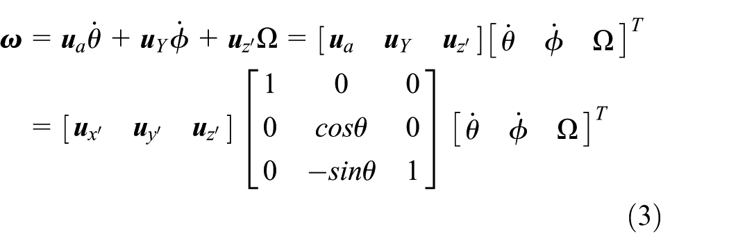
where
The kinetic energy of MWA can be written as

where
Finally, the kinetic energy of the flywheel is obtained by substituting equations (2) and (3) into equation (4) as follows

The potential energy of the flywheel is stored in the springs and can be written as

where
The dissipation of the system is given as

where
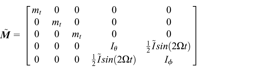
The motion equations are derived using equations (5)–(7) and Lagrangian methods as follows

The equations of motion are then obtained by differentiating L with respect to the generalized coordinates, and their derivatives, accounting for the external work, are as follows

Assuming small motion about x, y, z,

where


Disturbance input
Rotor mass imbalance
Rotor mass imbalance, including static and dynamic imbalance, is added by a series of small equivalent lumped masses to model the radial force and torque disturbances of the rotating wheel. Static imbalance is caused by the offset of the center of mass of the wheel from the axis of rotation. It is most easily modeled as a small point mass,

Rotor mass imbalance of MWA: (a) static imbalance and (b) dynamic imbalance.
The imbalance excitations are synchronized with a rotating speed of

where

where


where


where
Joint clearance
Kinematic joints between the rotor and the bearings are imperfect and inevitable due to manufacture and assemblage errors, as well as the eccentricity caused by rotor mass imbalance. The existence of clearance in joints leads to the dynamic impact on the system and further reduces the stability and accuracy of the mechanism. Therefore, it is critical to adopt an accurate contact force model to predict the dynamic characteristics of MWA.
A large number of models have been established for the contact force between clearance joints, and its development process includes the following four stages: the first is the purely elastic contact force model, Hertz’s contact law, 21 which does not account for energy dissipation during the contact process but is the basement of several dissipative contact force models; the second is the linear spring–damper contact force model, Kelvin–Voigt contact force model, 22 which considers the dissipative impact but disagrees with the real impact circumstance at the initial moment; the third is the best known nonlinear contact force models, Hunt–Crossley 23 and Lankarani–Nikravesh 24 contact force models, which take the aspects of material property, geometry, elastic deformation, energy dissipation, and restitution coefficient into account together; the last is the hybrid contact force model with nonlinear stiffness coefficient.14,15,25 However, there is a contact force model developed by IMPACT function in multibody dynamic software, ADAMS, which not only considers the effect of nonlinear energy dissipation process but also resolves the programming difficulty of collision detection in the abovementioned contact force models, and its equations can be expressed as 26
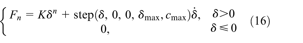

where

where

A modified Coulomb’s friction force model is used to depict the friction effect in clearance joint, which can be expressed as follows

where

where
Equations of motion for MWA with clearance
The dynamic model of MWA based on the disruption of rotor mass imbalance and the clearance of joint is established. The joint clearance leads to two different motion phases of bodies including the free movement of the bodies in the clearance and the contact and interaction of the bodies. MWA with clearances between bodies is a variable topology system. The variable topology system of MWA is solved using the dynamic segmentation modeling method. Therefore, the dynamic equation is obtained using the Lagrange multiplier method.
In the free motion phase, the dynamic equation is


where
In the contact and interact phase, the contact forces exist in the clearances between bodies. The dynamic equation is
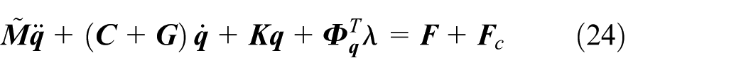

where
Dynamic simulation of MWA with clearance
Properties of MWA
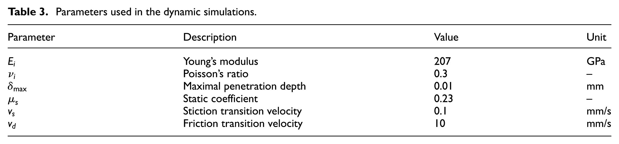
The structure of MWA is shown in Figure 4(a). The dynamic model of MWA, considering the effects of flexibility, mass imbalance and joint clearance together, is developed as shown in Figure 4(b). The finite element model of the flexible MWA model developed in PATRAN is imported to ADAMS, and the static and dynamic imbalance are added by a series of small equivalent lumped masses, which are defined as “0Dmss Element” in PATRAN. The locations of three lumped mass blocks are shown in Figure 3. The IMPACT-function-based contact is adopted in the joint clearance, and ADAMS/Solver computes the contact force from the IMPACT function available in the ADAMS function library. The mass and geometric properties of MWA are shown in Table 2, and the parameters used in the dynamic simulation are presented in Table 3.

Dynamic model of MWA: (a) configuration of MWA, here clearance is exaggerated for illustration and (b) flexible MWA with rotor mass imbalance and joint clearance.
Mass and geometric properties of MWA.

Parameters used in the dynamic simulations.
Numerical simulation of MWA with joint clearance
This section presents the extensive results obtained from computational simulations, and then the influences of clearance, driving angular velocity, and the friction coefficient on the dynamic characteristics of the MWA are further analyzed.
Influence of clearance size
To study the effects of clearance on the dynamic characteristics of MWA, the values for the clearance size,

Effects of clearance size on angular velocity of MWA: (a) angular velocity curves of MWA with different clearances and (b) partial enlarged detail of ②.

Effects of clearance size on angular acceleration of MWA: (a) ideal joint, (b)

Effects of clearance size on contact force of MWA: (a) ideal joint, (b)
The angular velocity curves of MWA with different clearances are nearly similar, which are all shaky around the ideal one after adjusting for some time, as shown in Figure 5. With the increase in clearance, the deviations between the peaks of the angular velocity curves of MWA with different clearances of 0.1, 0.3, and 0.5 mm and the ideal one become larger, which are 12.81, 24.14, and 37.94 deg/s, respectively; the relative differences are equal to 0.53%, 1.01%, and 1.58%, respectively. These results indicate that the larger the clearance size, the higher the amplitude, the lower the frequency of fluctuation, and the longer the adjusting time to reach the state of shaking around the ideal angular velocity curve.
Compared to the angular velocity curves, Figures 6 and 7 show that the existence of joint clearance has extraordinary obvious effects on the angular acceleration and contact force of MWA, which appears as an impulse type and presents high peak values. The peaks of the angular acceleration curves of MWA with the above three sets of clearance size are −2708.81, −4412.06, and −5755.34 deg/s2, respectively. The peaks of the contact force curves are 535.05, 659.53, and 789.11 N, which demonstrate that the larger the clearance, the more obvious the fluctuation amplitude of response becomes and the slighter the shaking frequency, that is, with the increase in clearance size, the lower the collision times with greater impact strength. Furthermore, the system response clearly repeats itself from cycle to cycle.
Influence of driving angular velocity
Defining the clearance size as 0.3 mm and the friction coefficient as 0.1, three different values for driving angular velocity,

Effects of driving angular velocity on angular velocity of MWA.

Effects of driving angular velocity on angular acceleration of MWA with clearance: (a)

Effects of driving angular velocity on contact force of MWA with clearance: driving angular velocity is defined as (a) 1200 deg/s, (b) 2400 deg/s, and (c) 3600 deg/s; (d) comparison of contact force curves of MWA with different driving angular velocities; and (e) partial enlarged detail.
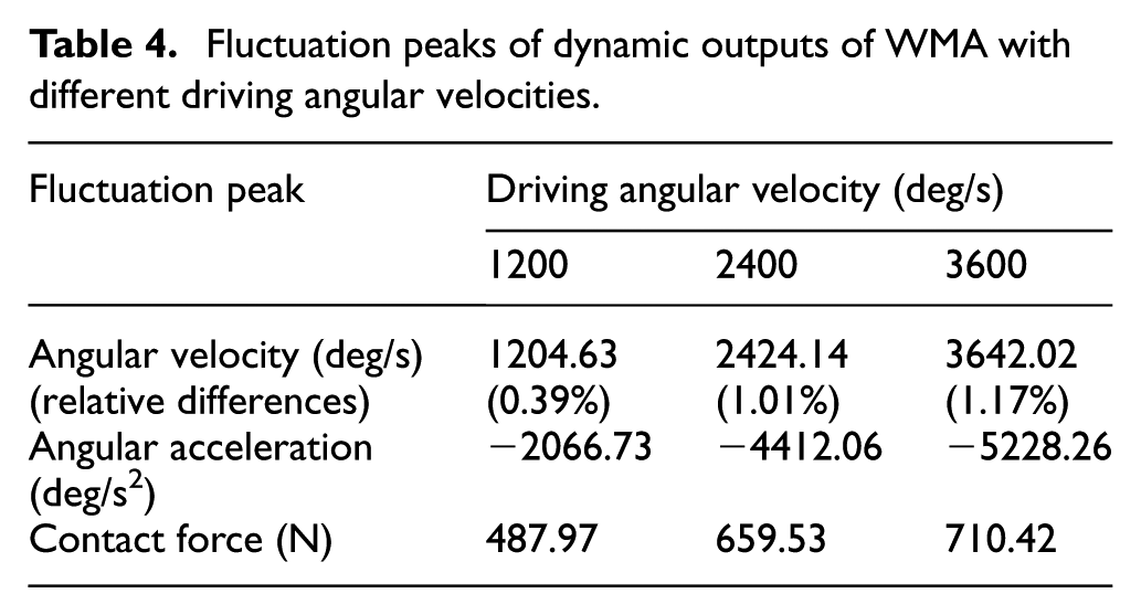
Figure 8 shows that the higher the driving angular velocity, the longer the required adjusting time. The fluctuation peaks of the angular velocity curves, the angular acceleration curves, and the contact force curves of MWA with different driving angular velocities are listed in Table 4. The table illustrates that the peaks of the abovementioned three dynamic characteristic curves increase with the increasing driving angular velocity. As shown in Figures 9 and 10, similar to the effects of clearance size on the dynamic response of MWA, the angular acceleration and contact force of MWA with different driving angular velocities appear for impulse type with few declining oscillations. It is obvious that the above dynamic characteristics of WMA with different angular velocities are high-frequency vibration with higher amplitude, which influences the positioning accuracy, movement stability, and reliability of the MWA system. These results are similar to the effects of clearance size on the dynamic response of MWA.
Fluctuation peaks of dynamic outputs of WMA with different driving angular velocities.
Influence of the friction coefficient
Defining the clearance size as 0.3 mm and the driving angular velocity as 2400 deg/s, three different values for the friction coefficient,
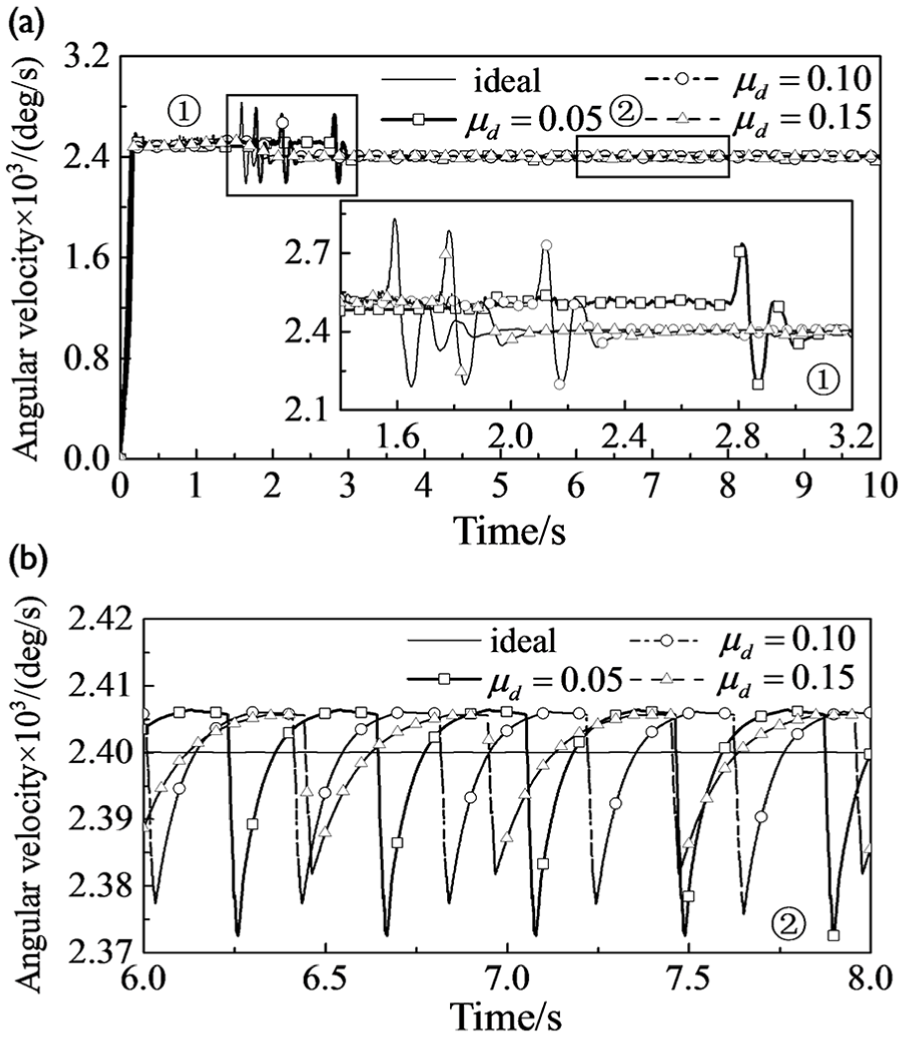
Effects of friction coefficient on angular velocity of MWA: (a) angular velocity curves of MWA with different friction coefficients and (b) partial enlarged detail of ②.

Effects of friction coefficient on angular acceleration of MWA: (a) angular acceleration curves of MWA with different friction coefficients, (b) partial enlarged detail, and (c) FFT analysis of angular acceleration of MWA with different friction coefficients.

Effects of friction coefficient on contact force of MWA: (a) contact force curves of MWA with different friction coefficients, (b) partial enlarged detail, and (c) FFT analysis of contact force of MWA with different friction coefficients.
Fluctuation peaks of dynamic outputs of WMA with different friction coefficients.
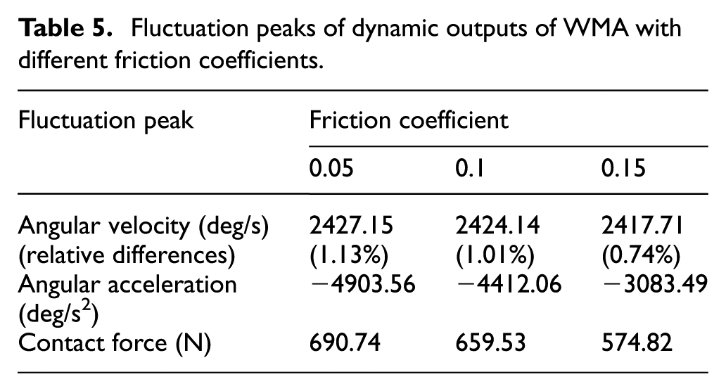
The results indicate that the friction coefficient can significantly affect the dynamic response of the system. The lower the friction coefficient, the more obvious the change in system response; in other words, the increase in friction coefficient leads to a smooth response of the WMA system because the friction and damping can dissipate energy during the work process of the mechanism. The low friction coefficient will slow the dissipation process, which leads to the instability of the system and deviation of the dynamic performance compared to the ideal mechanism.
Conclusion
In this article, the dynamic characteristics of a flexible MWA considering the disturbance of rotor imbalance and clearance joint are investigated using computational methodology. A nonlinear contact force model and a modified Coulomb’s friction model are adopted in the joint clearance of the rotor and the bearings, and the influences of the clearance, driving angular velocity, and friction coefficient on the dynamic behaviors of MWA are further analyzed.
From the numerical simulation results, it can be concluded that the existence of joint clearance has extraordinary effects on the dynamic system characteristics including the dynamic behaviors of MWA, namely, angular velocity, angular acceleration, and contact force. These characteristics are unstable around the ideal value, and the larger the clearance, the more obvious the fluctuation amplitude of the response and the slighter the shaking frequency. In addition, under the same clearance size and friction coefficient, the higher driving angular velocity causes more high-frequency and high-amplitude vibration in the dynamic characteristics. Moreover, defining the clearance size and driving angular velocity as constant values, the lower friction coefficient may lead to obvious shaking and poor dynamic system performance, which induces large amplitude of oscillation. The existence of the clearance joint has a crucial effect on the dynamic characteristics, which supports the idea that the model of clearance joints must be considered in the analysis and design of real mechanical systems.
Footnotes
Handling Editor: Jan Torgersen
Declaration of conflicting interests
The author(s) declared no potential conflicts of interest with respect to the research, authorship, and/or publication of this article.
Funding
The author(s) disclosed receipt of the following financial support for the research, authorship, and/or publication of this article: This research was supported by the National Natural Science Foundation of China (grant nos 1140220 and 11772256) and the Basic Research Foundation of NWPU (grant no. 3102016ZY002).