
Abstract
The article introduces a general solution for dynamic analysis of a planar multibody system with revolute lubricated clearance joint. An improved transition force model is established, which includes dry contact force and hydrodynamic forces, accounts for not only squeeze-film effects but also wedge-film effects, and is applicable to both long and short bearings. Then, the dynamic behaviors are presented based on this transition force model and a planar slider-crank mechanism with a lubricated revolute clearance joint. Different test conditions are considered in order to present a parametric study about the effects of clearance size, crank speed, and lubricant viscosity on the dynamic characteristics of planar multibody system with lubricated revolute clearance joint. As shown by numerical simulation results, it can be included that with larger clearance size and crank speed, as well as smaller lubricant viscosity, the system has higher vibration amplitude and lower minimum film thickness.
Keywords
Introduction
In general dynamic research of planar multibody system, it is assumed that all joints are perfect, so the effects of clearance and lubrication are often ignored.1,2 However, clearance joints are inevitable in all of the mechanical systems due to the demand of relative motion, manufacture and assemblage errors, as well as the influence of wear and material deformation. Furthermore, clearance joints cause impact reaction force and friction between journal and bearing, which are the sources of vibration, noise, and wear. Clearance joints also reduce reliability, stability, kinematic accuracy, and life of the mechanism systems.3,4 In order to reduce the influence of contact force and friction, except special conditions such as space field, joints in most of mechanism systems are designed to work with lubricant fluid. The hydrodynamic forces include squeeze and wedge effects, which make the journal and the bearing apart, so that even the maximum load occurs in lubricated clearance joint, the journal and bearing will not contact.5,6
Over the last years, numbers of numerical and experimental researches have been presented to study the effects of clearance joints on the dynamic response of multibody systems.7–15 Based on the most frequently used model proposed by Lankarani and Nikravesh, 7 Flores and colleagues.8–11 analyzed dynamic characteristics of slider-crank mechanism with clearance joint and found that clearance size, clearance number, input speed of crank and friction coefficient have obvious effects. Through numerical simulation and experimental analysis, Erkaya and Uzmay12–15 investigated the effects of clearance size, balancing, and link flexibility on kinematic and dynamic characteristics of mechanism with clearance joint. But the Lankarani–Nikravesh (L-N) model is more effective for the condition of large clearance size, small normal load, as well as coefficient of restitution near to 1.16–18 In order to overcome these drawbacks, Bai and Zhao2,19 extend the L-N model and presented a new hybrid contact force model. And a great number of researches have been done to present the effects of clearance joints using this hybrid contact force model. Wang and colleagues18,20,21 also set up three different impact force models, which are suitable for different conditions, and their model presented in Wang et al. 21 appeared to have a wide range of impact situation, even with low coefficient of restitution. Li et al. 22 present a novel transition force model for lubricated clearance joint, which is more accurate, efficient, and feasible than the Flores model. Tian et al. 23 presented and validated a new elastohydrodynamic (EHD)-lubricated spherical joint model for flexible multibody dynamics based on numerical simulations and commercial software ADINA.
However, all these works are based on considering the clearance in journal and bearing is dry, which means the effect of lubrication is ignored in most of these researches.
In fact, most of the clearance joints are lubricated, and the motion of the journal is opposed by the hydrodynamic forces due to the lubricant fluid. By integrating the pressure distribution evaluated with the aid of Reynolds’ equation, these hydrodynamic forces can be obtained. 24 Three typical hydrodynamic force models are frequently used in the dynamic simulation of multibody system with lubricated clearance joints, which are the Hamrock models, 25 Frêne et al. models, 26 and Pinkus–Sternlicht models. 27 Based on these models, some researchers have presented a few extensive works to study the effect of lubricated clearance joints on the dynamic characteristics of multibody systems. Considering the effects of clearance and lubrication, Roger and Andrews 28 presented a mathematical model for lubricated clearance joint, but this model ignores the wedge-film effect. Liu and Lin 29 extend the work of Roger and Andrews and developed a model which includes squeeze-film and wedge-film effects. Schwab et al. 30 presented an impedance method to study the effects of lubricated revolute clearance joint and the compliance of the links on the peak values of contact force. Flores et al. 24 showed a general and comprehensive methodology for modeling lubricated clearance joint, which is only applicable to long bearing. Later, Flores et al.5,6 introduced a force model for lubricated revolute clearance joint, which is a transition model from hydrodynamic force to dry contact force. It should be noted that hydrodynamic force in this transition model is the pure squeeze-film effects.
The main contribution of this work is that a general solution for the dynamic research of planar multibody systems is introduced, which have lubricated clearance joints, and in this article, the effects of clearance size, crank speed, as well as lubricant viscosity on the dynamic characteristics of planar multibody systems with lubricated clearance joints are studied.
It needs to be highlighted that in this study, an improved transition force model is introduced, which is based on the works of Flores et al.5,6 and Wang et al. 21 In section “Modeling revolute joints with clearance,” the model of revolute clearance joint is introduced; the transition model from hydrodynamic force to contact force is presented in section “Transition model from hydrodynamic force to contact force,” and it should be emphasized that the improved transition force model presented here accounts for not only squeeze-film effects but also wedge-film effects and is applicable to both long and short bearing. In section “Multibody system formulation,” the multibody system formulation with clearance joints is offered, and then, a planar slider-crank mechanism with lubricated clearance joint between connecting rob and slider is used as an example, and a large number of numerical simulations on dynamic responses are presented and discussed in section “Examples and numerical results,” and finally, the conclusions of this article are presented in section “Conclusion.”
Modeling revolute joints with clearance
Dry contact
In general kinematic and dynamic researches of multibody system, the revolute joint such as journal–bearing is assumed to be ideal or perfect, which means without clearance. In fact, the existence of clearance in journal–bearing joint is inevitable.
As depicted in Figure 1, the clearance size is the radius gap between journal and bearing and is evaluated as 8


Revolute joint with clearance.
Figure 2 shows a clearance journal–bearing joint with contact in a multibody system. Point


Revolute clearance joint with contact.
The value of e can be evaluated as

The penetration depth between the journal and bearing can be written as

where c is the radial clearance between journal and bearing defined as formulation (1).
The relative impact velocity vector between journal and bearing is evaluated by 31

where ωB and ωJ are the bearing and journal angular velocities, respectively, and tangential vector

So, the relative impact velocities to the plane of collision can be calculated by 31

where
Lubricated joint
In order to reduce the effects of impact force due to the clearance, such as vibration, friction, wear, and noise, most of the mechanical systems are designed to consider lubricated joints, and the high pressure generated in the fluid acts to keep the journal and bearing apart. 32
Figure 3 shows the clearance joint with lubrication. Compared with Figure 1, it can be observed that the gap due to clearance between journal and bearing is filled with a fluid lubrication, and the relative rational velocity of journal and bearing is considered in order to evaluate the effect of wedge-film.

Clearance joint with lubrication.
Figure 4 depicts a lubricated clearance joint with dynamic load in a multibody system. The fluid lubrication introduces high pressure, damping, and stiffness to the system, so the journal and bearing are apart until the dynamic load is larger enough, which means that the minimum lubrication film is below the safe value recommended, and metal-to-metal contact occurs between journal and bearing.

Lubricated clearance joint with dynamical load in a multibody system.
Different from the dry contact clearance joint, the eccentricity ratio

And the time rate of eccentricity ratio

Transition model from hydrodynamic force to contact force
Dry contact forces in joint with clearance

where

where L is the length of bearing and

where
When impact appears between the contact surfaces of clearance joint, the relative sliding motion also appears, so the friction effects should also be considered. This article used the improved coulomb friction force model introduced by Wang et al., 18 which is expressed as

where

where

Modified Coulomb friction force model.
Hydrodynamic forces in lubricated clearance joints
In general, the effects of fluid film pressure in lubricated clearance joint are evaluated by Reynolds’ equation, which is expressed as 33

where X is the radial direction, Z is the axial direction, h is the film thickness,
It is difficult to solve equation (15) directly, so an approximate method is introduced, which is the first term on the left-hand side is assumed as zero for the infinitely short bearing, and the second term on the left-hand side is defined as zero for infinitely long bearing. 5
Based on this method, three different hydrodynamic force models have been presented, which are the Hamrock models, 25 Frêne et al. models, 26 and Pinkus and Sternlicht models. 27
As the length-to-diameter (L/D) ratio is greater than 2, so-called infinitely long bearing, the Hamrock models are expressed as 25

where

For infinitely short journal–bearing, the Hamrock models are written as


The hydrodynamic force model presented by Frêne et al. 26 can be written as follows.
For infinitely long journal–bearing


For infinitely short journal–bearing


Pinkus and Sternlicht
27
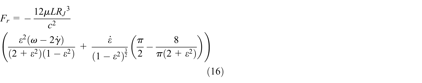
presented a hydrodynamic force model for infinitely long journal–bearing. For positive radial velocity of


For negative radial velocity of


The parameter k in equations of (23)–(26) can be expressed as

Based on a typical journal–bearing clearance joint, Flores et al. 6 presented a compare and analysis about the hydrodynamic force models shown by equations (15)–(27), and the results illustrated that Frêne et al.’s model indicates a free vibration without damping and Hamrock models and Pinkus–Sternlicht models represent a free vibration system with damping. Furthermore, Hamrock models and Frêne et al. models are suitable for not only long bearing but also short bearing, whereas Pinkus and Sternlicht models are suitable for only long journal–bearings. So, it can be concluded that Hamrock models are more effective and have a wider application range.
Improved transition model from hydrodynamic force to contact force
In order to study the transition between dry contact force and lubricated force in lubricated clearance joint, Flores et al. 5 developed a transition model, which extends the theory of elastohydrodynamic lubrication (EHL) and previous authors’ work. 30 The model is illustrated by Figure 6. As shown in Figure 6(b), the squeeze-film effects and dry contact effects are connected by a smooth curve and journal and bearing appear to be in contact, and as the hydrodynamic theory is not suitable, the model still ensures a stable and smooth transition between squeeze-film force model and dry contact force model.
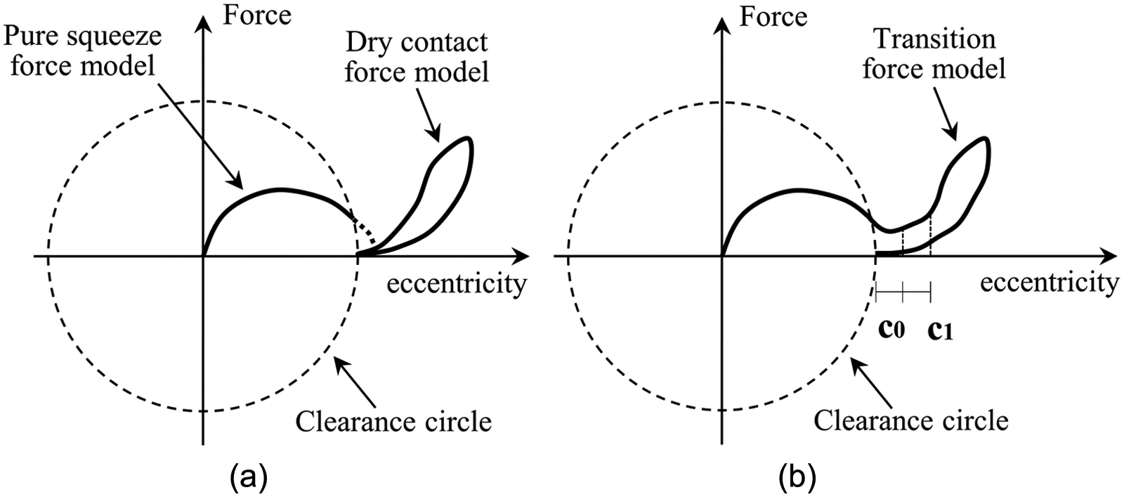
(a) Lubricated and dry contact force models and (b) transition force model.
Based on the work of Flores et al., this article introduces an improved transition force model, which can be evaluated as
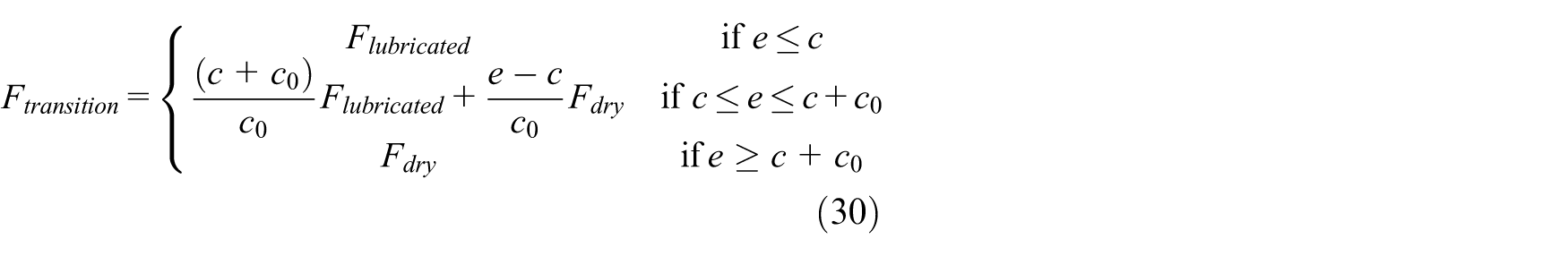
where

where
It should also be noted that the initial clearance is
The minimum film thickness value is introduced to judge whether or not contact and impact appear between journal and bearing and can be given by 32

In general, the safe film thickness in practical engineering design should not be smaller than 0.00015 mm/mm of bearing diameter.26,27
Multibody system formulation
The dynamic equation for planar multibody system with lubricated clearance joint can be written as a coupled set of differential and algebraic equations 34

where
Appropriate initial parameters of motion conditions, such as positions and velocities, are critical for dynamic simulation. Usually, the initial conditions can be obtained based on the kinematic analysis of system assumed to be ideal. The next initial movement conditions for each step can be acquired from the last state of the previous step. 34
Accurately identifying the relative motion condition between journal and bearing in clearance joint in real-time is also critical, and a state judgment equation is used, which can be calculated as 35

where
Considering the dynamic response of multibody with clearance joints is quite complex due to the impact between journals and bearings, and in order to guarantee the stability of the integration process, the integration is performed based on a predictor–corrector algorithm with variable step size, and the maximum integral step is defined as not more than 1e−4.
Examples and numerical results
Kinematic and dynamic analyses of model mechanism
As depicted in Figure 7, a planar slider-crank mechanism is selected here as an example of application in order to validate the improved transition force model developed in this article and evaluate the influences of clearance size, crank speed, and lubricant viscosity on dynamic behaviors of planar multibody system with lubricated clearance joint.
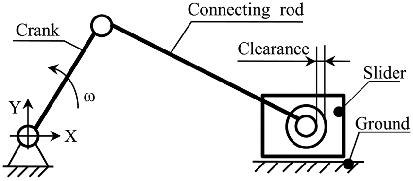
Slider-crank mechanism with a lubricated clearance joint.
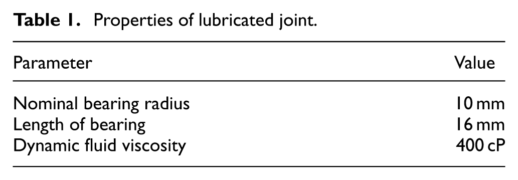
It is assumed that the slider-crank mechanism is made of crank, connecting rod, slider, and ground, which are all rigid, and there is a lubricated clearance joint. Mass and inertia properties of mechanism are shown as follows: the length of the crank is 50 mm and connecting rod is 300 mm. Mass of crank, rod, and slider is 0.194, 1.062, and 0.281 kg, respectively. And inertial moment of connecting rod is 0.034 kg m2. Table 1 presents the properties of dry contact and lubricated clearance joint. Journal and bearing have same material parameters of Young’s modulus of 207 GPa and Poisson’s ratio of 0.3. The restitution coefficient is 0.5, and coefficient of friction is 0.01.
Properties of lubricated joint.
The vector representation and the joint forces as a function of the input link position are shown in Figure 8(a) and (b), respectively.
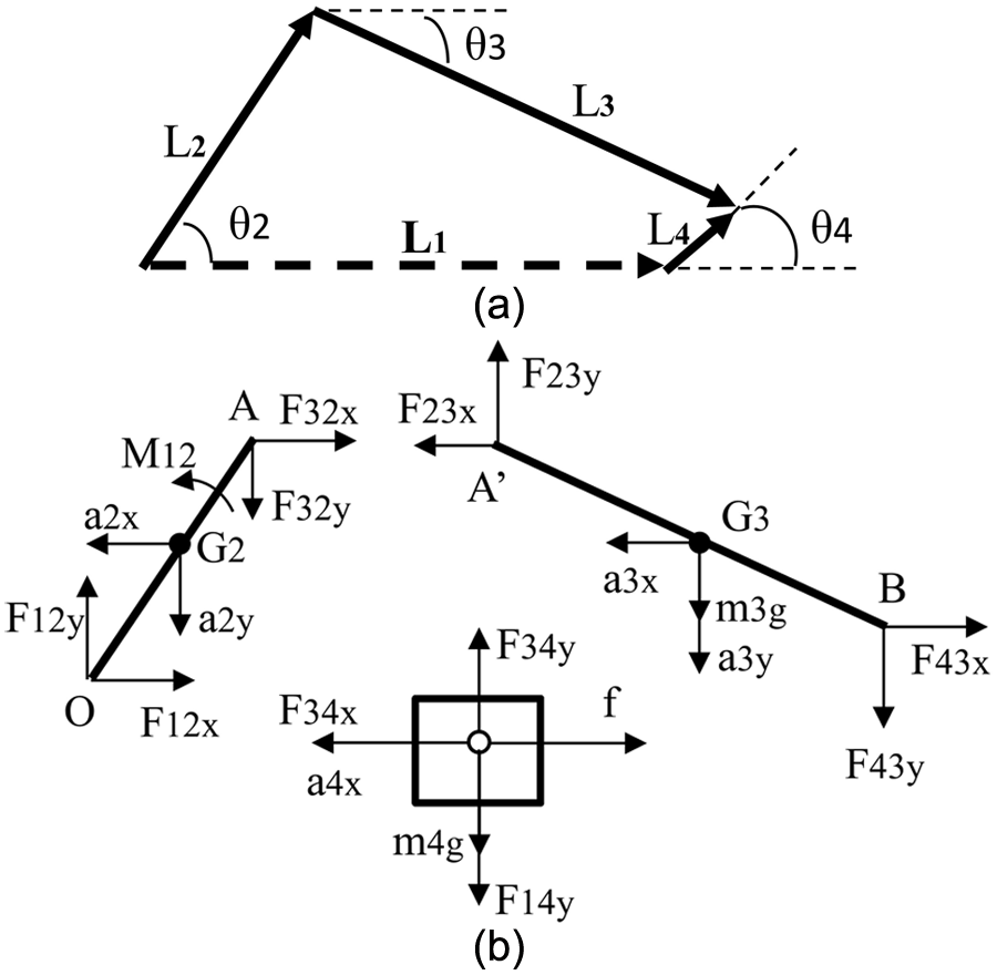
Slider-crank mechanism with a lubricated clearance joint: (a) vector representation and (b) representation of joint forces.
According to Figure 8, the positions and accelerations of the mass centers for crank and connecting rod are written as


where
As shown in Figure 8(b), equilibrium conditions of each link can be defined as


where
The reaction forces and relative velocities in clearance joint are given as


where
Numerical results
Assume that at the beginning of simulation, the crank and rod are aligned in the X-direction. Furthermore, in order to clearly understand the effects of clearance size, crank speed, and lubricant viscosity, the influence of flexibility links are neglected.
Influence of clearance size
In this section, the effect of clearance size on the dynamic response is investigated. It is assumed that mechanism has a constant speed of 500 r/min and fluid viscosity of 400 cP, as well as constant clearance sizes during simulation, which are equal to 0.1, 0.3, 0.5, and 1 mm, respectively.
First, the results of slider acceleration based on dry contact force model and the improved transition model are presented as depicted in Figure 9. It can be drawn that with the effect of clearance, the result of slider acceleration has an obvious vibration around ideal value, but the slider acceleration curve is almost coincident with the ideal result when the lubrication in clearance joint is considered.

Slider acceleration with clearance c = 0.1 mm: (a) dry contact joint and (b) lubricated joint.
Figures 10 and 11 represent the results of slider acceleration and joint reaction force, which are based on the lubricated joint with different clearances. It can be concluded that (1) the results of slider acceleration as well as joint reaction force are consistent during the first and the second rotation of crank, which means that the simulation system has achieved a steady state. (2) The slider acceleration curves and joint reaction force curves appear during slight vibration, and the larger the clearance size, the more obvious the vibration. But the vibration only occurs when crank angular positions are 180° and 540°, due to the influence of clearance on direction and values of lubricated force as mechanism near the dead positions.
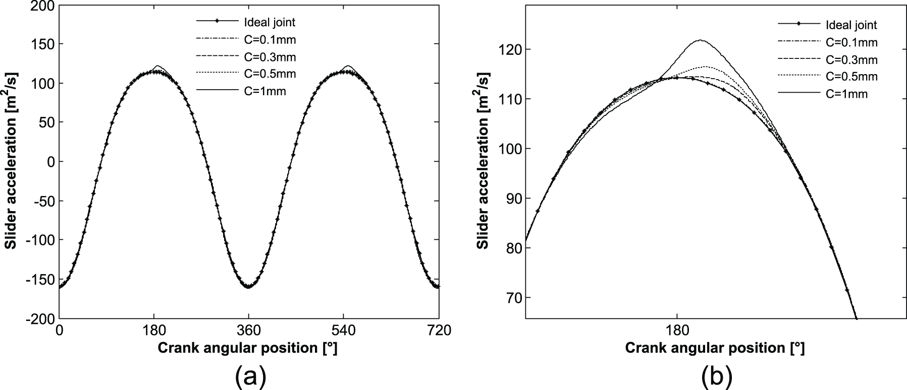
Slider acceleration for different clearance sizes: (a) two rotation periods and (b) enlarged view.

Joint reaction force for different clearance sizes: (a) two rotation periods and (b) enlarged view.
Figure 12(a)–(d) depicts the results of minimum film thickness curves, which are based on different clearance sizes, and the results exhibit that (1) the minimum film thickness curve is obviously affected by the clearance. (2) The lager the clearance size, the lower the minimum film thickness, which are 45.83, 34.13, 28.66, and 22.51 μm as clearance sizes are 0.1, 0.3, 0.5, and 1 mm, respectively.

Minimum film thickness for different clearance sizes: (a) c = 0.1 mm, (b) c = 0.3 mm, (c) c = 0.5 mm, and (d) c = 1 mm.
Influence of crank speed
The effects of crank rotary speed are investigated in this section. It is assumed that clearance size of 0.5 mm and fluid viscosity of 400 cP are constant.
Figures 13–15 illustrated the results of acceleration, joint reaction force, and minimum film thickness based on four different crank speeds, which are 300, 500, 800, and 1000 rpm, respectively.

Slider acceleration for different crank speeds: (a) 300 r/min, (b)500 /min, (c) 800 r/min, and (d) 1000 r/min.

Joint reaction force for different crank speeds: (a) 300 r/min, (b) 500 r/min, (c) 800 r/min, and (d) 1000 r/min.

Minimum film thickness for different crank speeds: (a) 200 r/min, (b) 500 r/min, (c) 800 r/min, and (d) 1000 r/min.
As observed from Figures 13 to 15, the effects of the lubricated clearance joint on the curves of acceleration, reaction force, and minimum film thickness are all similar, and appeared vibration near the dead position of mechanism, due to the influence of clearance on lubricated force. In addition, the higher values of crank speed and the lower values of minimum film thickness are observed when crank speed increases from 300, 500, and 800 r/min to 1000 r/min and the minimum film thickness decreases from 46.48, 28.66, and 14 μm to 7.46 μm, as illustrated in Figure 15.
Influence of lubricant viscosity
The influence of lubricant viscosity on the dynamic response is investigated in this section. It is assumed that crank has a constant clearance size and crank speed, which are 0.5 mm and 500 r/min, respectively. The lubricant viscosities are also constant during simulation, which are equal to 400, 300, and 180 cP.
Figures 16–18 illustrate the results of slider acceleration, joint reaction force, as well as minimum film thickness with different lubricant viscosity, which evidence the effect of lubricated clearance joint on dynamic characteristics. (1) Acceleration and reaction force curves appear due to obvious vibration near the dead position of mechanism, and the smaller the lubricant viscosity, the larger the vibration, which can be shown clearly in Figures 16(b) and 17(b). (2) The minimum film thickness is strongly affected by lubricant viscosity, when lubricant viscosity values decrease from 400 to 180 cP, the minimum film thickness changes from 28.66 and 17.78 to 1.86 μm, respectively. It can be concluded that the minimum film thickness is smaller than the safe film thickness when the lubricant viscosity value is below 180 cP, which means that lubrication between the journal and bearing is useless and the journal and bearing may appear to be in contact.

Slider acceleration for different lubricant viscosity: (a) two rotation periods and (b) enlarged view.
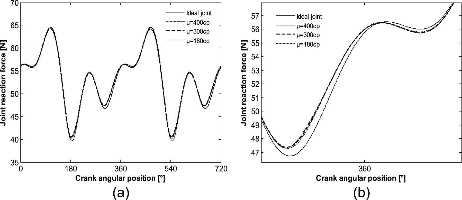
Joint reaction force for different lubricant viscosity: (a) two rotation periods and (b) enlarged view.

Minimum film thickness for different lubricant viscosity: (a) 400 cP, (b) 300 cP, and (c) 180 cP.
Conclusion
This article presented and discussed a general methodology for modeling and simulating multibody system with lubricated clearance joint, and a nonlinear improved transition force model for planar multibody system with lubricated revolute clearance joint was also provided, which accounts for not only squeeze-film effects, but also wedge-film effects and is applicable to both long and short bearing. In order to perform a parametric study on the dynamic response of multibody system with dry and lubricated clearance joint, a slider-crank mechanism with lubricated clearance joint between connecting rob and slider is used as an example, and different parameters are selected to analyze the effects, such as clearance size, input crank speed, and lubricant viscosity.
From a larger number of numerical simulations based on the conditions with different clearance size, input crank speed, and lubricant viscosity, it can be concluded that (1) comparing to the condition of dry contact, lubrication can effectively reduce the vibration caused by impact force and leads to a better dynamic response of the system. (2) Near the dead position of mechanism, the dynamic characteristics of mechanism appear as obvious vibration due to the influence of clearance on direction and values of lubricated force, and the larger clearance size and smaller lubricant viscosity result in the more obvious vibration. (3) It also can be drawn that with larger clearance size and crank speed, as well as smaller lubricant viscosity, the system has higher vibration amplitude and lower minimum film thickness.
Finally, it should be noted that the results presented in this work did not consider the influence of flexibility links, multiple clearance joints, different position of clearance joint, and the thermal effects at the clearance joints, which also have obvious influence on the dynamic characteristics of the multibody systems and should be considered in future researches.
Footnotes
Appendix 1
Acknowledgements
The authors would like to express their appreciation to the agencies.
Handling Editor: M Affan Badar
Declaration of conflicting interests
The author(s) declared no potential conflicts of interest with respect to the research, authorship, and/or publication of this article.
Funding
The author(s) disclosed receipt of the following financial support for the research, authorship, and/or publication of this article: The work is supported by National Natural Science Foundation of China (Grant Nos 51505381, 51275423, and 51675429), Education Foundation of Shaanxi (Grant No. 17JK0551), and Doctor Starting Foundation (Grant No. 106-451117002).