
Abstract
A new type of non-circular planetary gear train is proposed, in which the planetary gear is internally meshed with the sun gear and the ring gear at the same time. The structural form and transmission principle are analyzed, and the design method of non-circular gear pitch curves and related parameters of the gear train are discussed. The input–output relationship under various working conditions of the gear train is deduced. The precise tooth profile of the non-circular gears is obtained by the Boolean operation of MATLAB, then the virtual prototype model of the planetary gear train is established, and the kinematics simulation is carried out in the ADAMS software. The simulation results verify the correctness of the transmission principle and the theoretical analysis of the motion law.
Keywords
Introduction
The non-circular gear is a mechanism that can realize the non-uniform speed ratio transmission between the driving and driven gears. 1 Compared with the linkages, cams, and automatic control technology, non-circular gears have the advantages of low economic cost, compact structure, accurate transmission ratio, and good dynamic characteristics. Due to the precise transmission ratio, non-circular gears and their combined mechanisms have an irreplaceable role in many occasions with special motion and force requirements. Therefore, many scholars have done a lot of research in related design theory and engineering applications.
Non-circular gears can output a specific motion law, and thus can be used as a function generating mechanism, which has the advantages of simple structure and good transmission characteristics.2,3 D Mundo et al. 4 studied the five-bar linkages with non-circular gears and proposed an optimization of the mechanism by defining the objective function on the basis of proper dimensional and kinematic criteria. JY Liu et al. 5 designed a pair of elliptical gears to substitute the anti-parallel four-bar linkage and studied the specific trajectory curves generated by elliptical gears. D Barkah et al. 6 proposed the theory of using non-circular gears to balance the swinging force and torque of the linkage mechanism and JY Han 7 applied the theory to the space linkage mechanism and explained the design method of the non-circular gear for realizing the complete dynamic balance of the mechanism. O Karpov et al. 8 investigated the applicability of non-circular gears for preventing resonance oscillations in gear mechanisms. AA Prikhodko et al. 9 and Zheng et al. 10 studied the application of non-circular gears in intermittent motion mechanisms. JH Kerr and colleagues11,12 and Hebbale et al. 13 studied the application of non-circular gears in infinitely variable transmission. M Addomine et al. 14 discussed the landmark contributions of the Italian clockmaker Giovanni Dondi to the mechanical design of astronomical clockwork which demonstrates the unique application of non-circular gears in astronomy. Breaking through the traditional mode of non-circular gears, D Liu et al. 15 presented a new gear mechanism composed of a cylinder involute gear and an eccentric face gear to implement a synthetic motion; F Zheng et al. 16 proposed the definition of variable center distance gear, which is a new form of non-uniform transmission.
Regarding the generation of non-circular gears, relevant scholars have conducted in-depth research on the processing theory and manufacturing process of non-circular gears in recent years. I Zarębski and T Sałaciński 17 presented methods for designing of non-circular gears, including internal and external gears with spur or helical teeth and proposed the context analysis method to find non-circular gears’ flank. Y Liu 18 researched the gear shaping strategy for internal helical non-circular gears and conducted comparative analysis of four linkage models. F Zheng and colleagues19,20 proposed a 3-linkage model with an equal arc-length cutting method involving feed and investigated curvilinear non-circular gear generation based on face-milling method. K Shi et al. 21 proposed a method for processing non-circular bevel gear with concave pitch curve using bevel gear cutter enveloping.
Non-circular planetary gear train (PGT) absorbs the advantages of traditional PGT and non-circular gear mechanism and has the characteristics of compact structure, large transmission ratio, and variable transmission ratio, so scholars have conducted a lot of research on it. Yokoyama et al. 22 studied the design method of the inner and outer pitch curves of the non-circular PGT and proposed the conditions for avoiding interference. GY Volkov et al. 23 proposed a new approach to the geometric synthesis of non-circular gears for a rotary hydraulic machine. D Mundo 24 proposed a new type of non-circular PGT and studied its pitch curve design and tooth profile generation method. LS Guo et al. 25 developed the kinematic parametric equation for an eccentric PGT and studied a rice transplanting mechanism with the gear train.
As shown in Figure 1, there are mainly four types of traditional non-circular PGTs: N-G-W, N-W, W-W, and N-N.9,10,14,22–25 Among them, the N-G-W type has a single row with smaller axial dimension, and its radial dimension is slightly larger than the latter three types. N-W, W-W, and N-N are in the form of double rows, although the radial dimension can be reduced, the axial dimension is inevitably increased. In addition, these four types of traditional non-circular PGTs generally use several planetary gears to share the load, so there is a possibility of uneven loading. 26 In this article, a new type of coplanar double internal meshing non-circular planetary gear train (CDIMN-PGT) is proposed, which has the characteristics of compact structure, high power density, and the ability to output a specific regular rotational motion. Compared with traditional non-circular PGTs, CDIMN-PGT has only one planetary gear, thus avoiding the uneven load problem that may occur with multiple planetary gears. Due to the structural specialty, the modulus of the sun gear and the ring gear can be different, which reduces the difficulty of teeth matching. In addition to the internal meshing between the planetary gear and the ring gear, the planetary gear and the sun gear are also internally meshed, that is, double internal meshing, and the internal meshing is advantageous for improving the contact ratio of the gear transmission. 27 The design method of the pitch curves of the gear train based on internal high-order non-circular gears is proposed, and the boundary conditions of the design parameters are analyzed. The theoretical analysis of the transmission ratio of the gear train under different working conditions was carried out and kinematic simulation was accomplished in the ADAMS software.

Several traditional non-circular planetary gear trains: (a) N-G-W type, (b) N-W type, (c) W-W type, and (d) N-N type.
Transmission principle
The main structure of CDIMN-PGT is shown in Figure 2. The gear train is mainly composed of the sun gear, the planetary gear, the ring gear, and the planet carrier. The sun gear, the planetary gear, and the ring gear are all non-circular gears. The planetary gear has both inner and outer teeth, respectively, meshing with the sun gear and the ring gear, thereby transmitting motion and power. The planet gear makes a planetary motion that revolves around its own axis

Main structure of CDIMN-PGT: (a) kinematic sketch and (b) pitch curves.
Pitch curves design and analysis
Non-circular gears are a key component of CDIMN-PGT. Since the non-circular gear pairs
Internal non-circular gear pair
Unlike the external non-circular gear pair, the internal non-circular gear pair is composed of an external non-circular gear and an internal non-circular gear. Assume that the external gear is the driving gear and the internal gear is the driven gear. Due to the particularity of the internal non-circular gear, the order

where

Pitch curves of internal non-circular gear pair.
In order to make the teeth evenly distributed on the pitch curve, the following conditions must be met
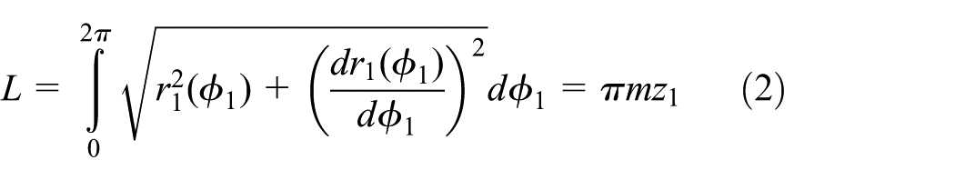
where L is the circumference of the driving gear pitch curve, m is the modulus, and
Transmission ratio of internal non-circular gear pair is

where A is the center distance.
According to the pitch curve closure condition, 1 the following equation can be obtained

Let
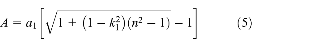
It can be seen from equation (5) that the center distance A is negatively correlated with the eccentricity and positively correlated with n.
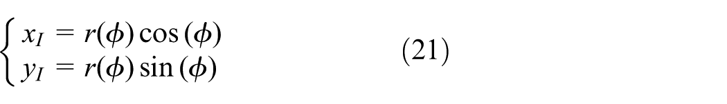
The pitch curve equation of the driven gear is as follows

namely

According to equations (1), (3), and (5), the transmission ratio of internal non-circular gear can be expressed as follows

Center distance equal condition
Ensuring that the center distances of the two pairs of non-circular gears G12 and G34 are equal is the basic condition for achieving correct transmission. And the center distance is determined by the relevant parameters of the pitch curve. Therefore, when designing CDIMN-PGT, the parameters of the two pairs of non-circular gear pitch curves are usually coordinated according to the condition of the equal center distance. The center distance equal condition for the non-circular gear pair

It can be known from equation (5) that the following relationship exists at this point

where
It is known from equation (8) that the transmission ratio of the internal non-circular gear pair is related to the order and eccentricity of the driving and driven gear. Therefore, the center distance equal condition can be satisfied by adjusting only the major axis radius ai (i =1,3) without changing the gear ratio. In the case where the order of the driving and driven gear is determined, let the eccentricity

Major axis radius
Boundary conditions without interference
The planetary gear of CDIMN-PGT can be regarded as being composed of two coaxial internal non-circular gears, and the inner and outer teeth are, respectively, meshed with the sun gear and the planetary gear. When designing the planetary gears, the pitch curves of the inner and outer non-circular gears should not be interfered. Only in terms of geometric relationship, the maximum value of the inner pitch curve’s polar radius should be less than the minimum value of the outer pitch curve’s polar radius. However, considering the teeth matching and the installation method of the planetary gear, the above conditions cannot meet the requirements. Therefore, it is necessary to leave a certain gap

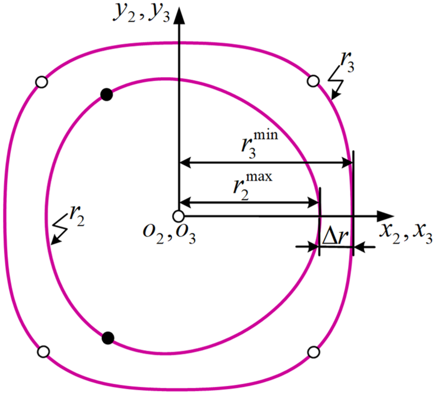
Limit position of the inner and outer pitch curves of the planetary gear.
According to equations (1), (7), and (11),

To simplify the analysis,

By solving equation (14), it can be obtained that
Kinematic analysis
As shown in Figure 2, the rotational speeds of the gears in the non-circular gear pairs
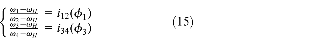
Since the internal teeth of the planetary gear are fixed to the external teeth, the following constraint can be obtained

Multiplying the left and right sides of the two subtypes of equation (15), the following equation can be obtained

The specific rotational speed relationship between the sun gear, the ring gear, and the planet carrier can be obtained by deforming equation (17) as follows

What is discussed above is only a special case. In fact, there may be a phase angle

Phase angle
Working state and output rotational speed of CDIMN-PGT.

In order to facilitate the description of the kinematics of CDIMN-PGT, a set of design examples was analyzed. Through the design method of CDIMN-PGT pitch curve described in the previous chapter, the specific design parameters of each non-circular gear are obtained, as shown in Table 2.
Design parameters of non-circular gears.

Through Table 2, the transmission ratio function of the non-circular gear pairs

Transmission ratio curve under different working status: (a) Working status IV, (b) Working status V, (c) Working status VI, and (d) Working status VII.
Influence of planetary gear phase angle
on transmission ratio
Taking the working state IV as an example, the relationship between the transmission ratio of the gear train and the phase angle

As can be seen from Figure 7, the transmission ratio

Relationship between phase angle
Influence of eccentricity k1 on transmission ratio
Taking the working state VII as an example, the relationship between the transmission ratio of the gear train and the eccentricity

From equations (8) and (20), the variation of

Relationship between eccentricity
Non-circular gear tooth profile generation
In this article, a MATLAB Boolean operation method based on the envelope principle is proposed to obtain an accurate tooth profile of non-circular gears. This algorithm continually performs Boolean subtraction operations between a region enclosed by the tooth profile of the shaper cutter and the closed region of the processed non-circular gear blank contour. In this process, the region enclosed by the blank is continuously cut according to the envelope principle, so the blank contour curve is also continuously iterated, and finally the complete non-circular gear tooth profile curve is obtained. Since there are few studies on the profile generation of internal non-circular gears, the algorithm is verified by the internal non-circular gear profile generation.
Coordinate transformation
The pitch curve of the non-circular gear can be expressed as
The unit tangent vector

where
Since the unit normal vector

The basic principle of the non-circular gear shaping is to ensure that the pitch circle of the pinion shaper cutter is purely rolling on the pitch curve of the non-circular gear. As shown in Figure 9, it is assumed that the non-circular gear is fixed on the plane, and the coordinate system

Illustration of coordinate systems
According to the pure rolling relationship between the pitch curve and the pitch circle, it can be seen that when the polar angle of the non-circular gear is

where
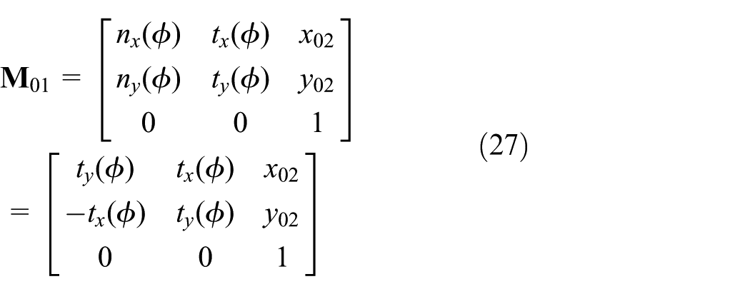
According to the above derivation and geometric relationship, the coordinates of the rotation center

According to the basic coordinate transformation relationship, the angle between the two coordinate systems

The coordinate transformation relationship between coordinate systems
According to the coordinate transformation relationship derived above, assuming that the tooth profile equation of the shaper cutter is

Tooth profile extraction
According to the coordinate transformation method described in the previous section, it is easy to obtain the envelope curves of the non-circular gear tooth profile and then the complete tooth profile curve of the non-circular gear can be obtained by extracting the boundary of the envelope curves. The extraction process mainly relies on MATLAB’s Boolean operation on two-dimensional closed regions. As shown in Figures 10 and 11, it is assumed that the region surrounded by the contour curve of the gear blank in the plane is


Shaper cutter profile.

MATLAB Boolean operation to extract the tooth profile curve.
The tooth profile and basic parameters of the shaper cutter are shown in Figure 10, where m is the modulus. According to the basic parameters of each non-circular gear in Table 2, the tooth profile curve of the CDIMN-PGT is obtained using the tooth profile extraction algorithm described above, as shown in Figure 12.

Tooth profile of the CDIMN-PGT.
Virtual prototype and simulation
The non-circular gear tooth profile obtained in the previous chapter is actually composed of a large number of two-dimensional coordinate points. Therefore, after obtaining the tooth profile points, the non-circular gear pairs

Virtual prototype model of the CDIMN-PGT.
The transmission ratio of the CDIMN-PGT in the single input-output state is simulated. From the input–output relationship of the gear train in the last four working states of Table 1 and Figure 6, it can be seen that the transmission ratio of the gear train in working state IV and V is reciprocal, and the transmission ratio of working states VI and VII is also the same, so only the transmission ratio under working states IV and V is simulated. The simulation results are shown in Figures 14 and 15, respectively.
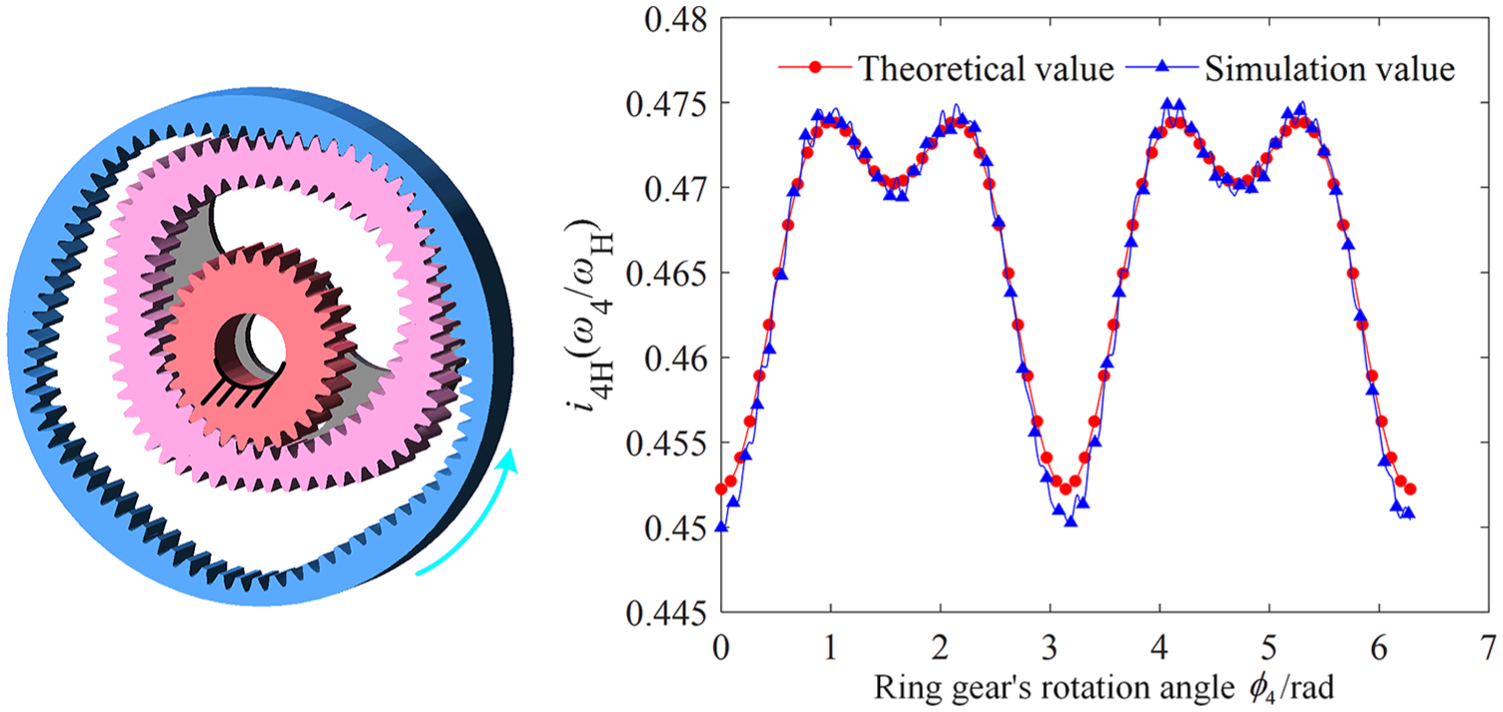
Working state IV transmission ratio simulation result.

Working state VI transmission ratio simulation result.
It can be seen from Figures 14 and 15 that the two sets of simulation values have the same period as the theoretical value, the amplitudes are relatively close, and the simulated values at the peaks and troughs deviate significantly from the theoretical values. The error sources mainly include the tooth profile accuracy of the non-circular gears and the inertial force generated by the dynamic imbalance of the non-circular gears. Among them, the influence of the tooth profile accuracy on the simulation results is reflected in the slight fluctuation of the simulation value near the theoretical value, and the influence of the inertial force of the non-circular gears on the simulation result is manifested in the difference between the simulated value and the theoretical value at some positions. These positions are mainly at the peaks and troughs of the transmission ratio curve.
Conclusion
The pitch curve design method of CDIMN-PGT is studied. The boundary conditions of the planetary gear design parameters are derived from the geometric relationship.
The transmission characteristics of the gear train are analyzed from the kinematics. The input–output relationship of the gear train under various working conditions is derived. The influence of the eccentricity of the non-circular gear and the phase angle of the planetary gear on the overall transmission ratio of the gear train is analyzed.
Combined with the specific design example, the precise tooth profile of the non-circular gear is obtained by the Boolean operation function of MATLAB software. This method is simple and efficient. Based on this, the virtual prototype model of the gear train was established and its kinematics simulation was carried out in the ADAMS software. The simulation results verify the correctness of the gear train design method and kinematics theory analysis.
Footnotes
Handling Editor: Shahin Khoddam
Declaration of conflicting interests
The author(s) declared no potential conflicts of interest with respect to the research, authorship, and/or publication of this article.
Funding
The author(s) disclosed receipt of the following financial support for the research, authorship, and/or publication of this article: This work was supported by the National Natural Science Foundation of China (51675060), the Fundamental Research Funds for the Central Universities (106112017CDJPT280002), the Equipment Pre-Research Project (No. 3010519404), and the Chongqing University Graduate Student Research Innovation Project (CYB18023).