
Abstract
Railway transportation demands more efficient and accurate rail wear inspection systems to ensure the train operation safety. To obtain continuous three-dimensional data, a structured light rail wear inspection system is developed in this article, and the data processing method for aligning the point cloud from structured light scanning to the nominal computer-aided design model of the rail is investigated. For further data registration, the point cloud of the computer-aided design model is generated and the normal vectors of these points are calculated. In the coarse registration, conformal geometric algebra is applied to align the segmented point clouds by intuitive geometric calculations to those from the computer-aided design model. In the fine registration, the accurate alignment of the point clouds is implemented by the iterative closest point algorithm. The vertical and lateral wear amounts are obtained on the cross section by slicing the aligned three-dimensional point clouds data. Finally, the proposed system and method are validated by comparing the vertical wear amounts with the two-dimensional laser scanning and contact measurement results.
Introduction
The demands for the inspection of railway system increase quickly with the significant progress of high-speed railway. As the most basic part of railway traffic, rails must be effectively inspected to ensure the safety of railway traffic so as to provide a stable environment for the train. For high-speed rails, the driving conditions become more stringent and it requires higher rail surface accuracy with the increased speed of the train, thus the rail wear inspection is significant. The traditional rail wear inspection is evaluated with two-dimensional (2D) data on the cross-sectional plane. To acquire the wear amounts of the rail in the three-dimensional (3D) scale, more effective data processing and registration methods are required continuously.
Contact and non-contact rail wear measurement system all have been investigated and developed. MiniProf BT Rail provided a contact inspection product by attaching a rod to the rail surface. After the measurement, the wear amount is calculated by its software system. 1 OPTIMESS released non-contact solution with the laser scanner by scanning along the rail to capture the profile. 2 The non-contact laser measuring system from MERMEC could be mounted on the train for railway track geometry inspection. 3 Similarly, the laser scanning method is utilized to measure the geometry of worn cutting tools. 4 For cutting tool wear evaluation, the laser sensor inspected the 3D profile by movement. 5 To calculate wear amount, the profile data registration to the referenced model is needed. Some 2D inspection method depended on the registration by aligning the arcs on the rail profiles combined with part of circles with center positions. 6 In another 2D method, particle filter was utilized for fitting a series of cross sections from a monocular vision system to the 3D model. 7
In the 3D inspection with high accuracy, structured light measurement is an effective way for profile scanning, which is encoded by point, line, fringe, grid, or other complicated patterns. 8 A type of line structured light vision sensor was applied in inner rail profile meazsurement. However, it is still 2D scale inspection because the interval between two consecutive measurements reaches about 190 mm. 9 Another line-structured light vision method was mentioned in Zhou et al. 10 for rail profile measurement, and the 3D profile of the rail was generated by splicing all the 2D profiles together simply. Rail profile was obtained by a 3D scanner in Zhou et al., 11 but the rail profile alignment was implemented on a 2D cross section of the rail. To inspect continuous rail profile, stripe structured light scanners were introduced in Chen and colleagues,12,13 and the comparisons between the point cloud data and 3D computer-aided design (CAD) model were conducted. The 3D point cloud was also introduced to reconstruct the surface of the worn parts for remanufacturing. 14 In biomedical engineering, the 3D digitalization process evaluated the polyethylene acetabular wear by point cloud comparisons. 15
To inspect the worn profile, data registration is a critical step which aligns the actually acquired data to the referenced model for comparison aim. When it comes to handling point cloud registration problems, iterative closest point (ICP) algorithm is widely used. The convergence of this algorithm is ensured by the input states of the two groups of data. 16 In the comparisons of Chen and colleagues’s12,13 studies, the point clouds from 3D scanner were aligned to those from CAD models in coarse and fine registrations. For good initial pose estimation, sample consensus initial alignment (SAC-IA) was used in the coarse registration. Although SAC-IA is a geometrical-based alignment method, the point feature histograms (PFH) had to be generated for this algorithm. 17
Although the 3D measurement by point cloud is practical in wear inspection, general registration methods are usually difficult to align the models with a good initial input which is influenced by the noisy point cloud with wear information or indirect feature description. To inspect the rail wear with continuous 3D information and provide a better initial input for the alignment between the point clouds, a structured light rail wear inspection system is developed, and an intuitive registration method based on conformal geometric algebra is introduced to solve the alignment problem of the noisy data from structured light scanning without complicated feature description. This article is divided into four main parts. First, the design of the rail wear inspection system is described. Second, both the CAD data and point cloud are processed for their alignment. Next, the point cloud registration based on geometric calculations is implemented, and then, the online inspection is implemented. Finally, the vertical wear amounts are compared with 2D laser scanning and contact measurement results to validate the proposed method.
Structured light rail wear inspection
The structured light measurement depends on machine vision technology. In the measurement, the image with a certain pattern of light is projected on the scanned objects, and then, the image is distorted by the profile of the objects. By reverse calculation, the 3D information of the objects is recovered by the image with the distortion captured by machine vision system. The scheme for rail wear inspection by 3D structured light is shown in Figure 1. In the system, the encoded fringe like the structured light is acquired by camera 1 and camera 2, and the corresponding points in the two images are calculated by binocular vision principle so as to generate the 3D point cloud of the rail. The charge-coupled device (CCD) cameras here have 1600 × 1200 resolution with the lenses of 16 mm focal length, and the digital projector has 1920 × 1080 resolution with a 600 lumen light source.

The scheme for rail wear inspection by 3D structured light.
A trolley is designed to mount the structured light scanner as Figure 2. In order to obtain the point clouds in multiple views of the scanner, a mechanism with the degrees of freedoms in left-right, up-down translations and rotation around its support is developed. By moving the scanner along the direction of the rail, the point cloud of the rail in continuous regions could be collected for combining into the complete data.

Trolley for the structured light data acquisition.
With the point cloud from 3D structured light scanning, the rail wear inspection requires the alignment of the point cloud to the rail model without wear. However, most of the models from CAD system are not point cloud format. Thus, the data processing of the nominal CAD model is required to generate the point clouds from its surface with the position and orientation information of points. The coarse registration of the scanned point cloud to that from nominal CAD model depends on the calculation of the translation and rotation values so that the two point clouds can be aligned roughly on their center positions and main orientations. For accurate wear inspection, the fine registration should be conducted by reducing the alignment errors from point to point within the two point clouds. When the 3D comparison results between the two point clouds are obtained, the wear amount on any 2D cross section of the rail could be calculated by the 3D comparison information. The data process steps above are shown in Figure 3.

Data process steps of rail wear inspection.
CAD data processing
With the data acquired by the structured light scanner, point cloud alignment is the basic step for structured light data processing to calculate the rail wear amount. In general rail wear inspection, the cross section obtained is compared with the nominal CAD data in 2D scale. For the structured light inspection result, the registration between the point cloud data and the CAD model is in the 3D scale. The rail CAD model is in its frame style as shown in Figure 4. Thus, it is required to be converted into point cloud before the registration.

Rail CAD model in its frame style.
In the conversion of the CAD model, the densities of the target and reference point clouds should be considered for the registration. The triangles in the CAD model are divided and the points are sampled in them randomly. As a result, points are created from the CAD model, which form the point cloud with the similar density as the scanned point cloud as shown in Figure 5.

Point cloud sampled from the CAD model.
The normal vector is an important parameter for describing the geometric features of the point cloud, which is the basis for a series of point cloud data processing because the feature extraction, curvature calculation, and rendering of point cloud all depend on it. However, the point cloud from structured light scanning only contains 3D coordinates without the direction information. The solution of the least squares method for fitting the plane of the normal vector is realized by principal component analysis. The geometric distribution of these points could be utilized to estimate the normal vectors. For each point

where k is the number of neighbored points,

Rendered normal vectors of rail point cloud.
Point clouds registration based on geometric calculations
In the alignment between the point clouds from CAD model and inspection data, the registration process is divided into coarse registration and fine registration by different surfaces on the rail point cloud. Fine registration is implemented by ICP method in this article, which requires a good initial input. To handle the alignment problem of the noisy data from structured light scanning by an intuitive mean, a registration method based on conformal geometric algebra is introduced.
Outline of conformal geometric algebra
Conformal geometric algebra provides an intuitive representation of various geometric objects and geometric transforms. In Euclidean space, the basis is 1,
For the point, the base vector

If the center is set as c and the radius is set as

The dual form of the subspace A can be described as given in equation (4)

The outer product of points A, B, C, and D generates a dual sphere

The outer product of points A and B and the infinity generates a line L as equation (6)

The outer product of points A, B, and C and the infinity generates a plane F as given in equation (7)

The outer product of three points A, B, and C generates a cycle Y as given in equation (8)

Set l as the unit direction vector and

Set


The rotation of the point X can be described as given in equation (12)

In conformal geometric algebra, the geometric objects, including line, plane, circle, and sphere, all could be represented by the outer product of points X as in equation (13) to facilitate the transforms

The translator T is introduced similar to that of the rotor as in equation (14) in Euler form

Thus, X is transformed by T as in equation (15)

Motor M is a type of transform in which transformation T is applied to the rotor R. It defines the general motion as shown in equation (16)

Coarse registration method based on conformal geometric algebra
Set the point cloud from the CAD model as P and that from the structured light scanning is Q. They are written as equations (17) and (18)


where

Similarly, the orientation of the point cloud could be also defined as a line by averaging the normal vectors of the points.
For the nonlinear rigid body motion estimation from noisy data of conformal geometric algebra objects, the motor for point set and line set is obtained by the formula of the optimization. 19 The motor could be applied to both centroids and averaging the normal vectors directly as in equation (21) for the models composed of different point clouds

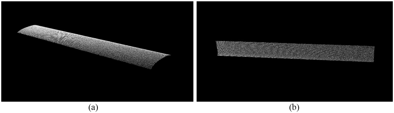
The point cloud shown in Figure 7 comes from the inner side of the rail. The point in such structure feature cloud is segmented into three planes.

Point cloud from the inner side of the rail.
To enhance the searching and extracting efficiency, the point cloud is assigned to a Kd-Tree, and the Euclidean clustering is applied to extract the points on the same plane of the rail web. 20 The points on the rail head part are clustered by judging the surface normal in specified searching radius. The segmentation result of the rail web and rail head is illustrated in Figure 8.

Segmentation result of the rail web and rail head.
It is necessary to continuously extract the planes in the point cloud of the rail head. To recognize these planes, the parameters of planar features are estimated by Random Sample Consensus (RANSAC) algorithm. Rail head includes the top surface and the side surface, so the segmentation is conducted by iteration. The points are determined on or out of the plane by the threshold of distance, and the result is shown in Figure 9.
Segmented top surface and side surface of the rail head.
With the segmentation results, three groups of centroids and orientation lines are calculated for each point cloud. By substituting them in formula (21), the solution is obtained by the Levenberg–Marquardt algorithm. With the initial transform by the coarse registration, the fine registration is conducted by the ICP algorithm. The alignment result of the structured light scanning data (with green color) and point cloud from the nominal CAD model (with white color) is shown in Figure 10.

Alignment result of the target point cloud to the nominal CAD model.
Online inspection results
To test the performance of the proposed rail wear inspection system and method, the online inspection was carried out on the high-speed railway station at Chengdu, China. The rail is the 60 kg rail in Chinese National Standard TB/T2314, and the rail inspected with 500 mm length is a straight section within the turnout. The trolley working on the railway for data acquisition is shown in Figure 11. The structured light scanner mounted on the trolley can cover 700 × 700 mm measuring area with 0.02 mm deviation of calibration when the measuring distance is between 800 and 1200 mm.

Trolley working on the railway for data acquisition.
The data processing methods proposed in sections “CAD data processing” and “Point clouds registration based on geometric calculations” are applied for registration. The alignment result of the two groups of the point cloud is shown in Figure 12. The colored points are the registered point clouds according to the point-to-point distances (the redder the lager) from them to the point cloud from the CAD model.

Alignment result of the target point cloud to the nominal CAD model.
In current Chinese National Standard, rail wear is described as lateral wear and vertical wear, and they are evaluated on the 2D scale, so the aligned point clouds above are sliced by cross-sectional planes and projected to these planes with the data in 1 mm range on both sides of the planes along the rail. On the cross-sectional plane, the color map shown in Figure 13 is generated according to the distances from these points to the nominal 2D profile of the rail, which can also describe the wear amounts in different colors.
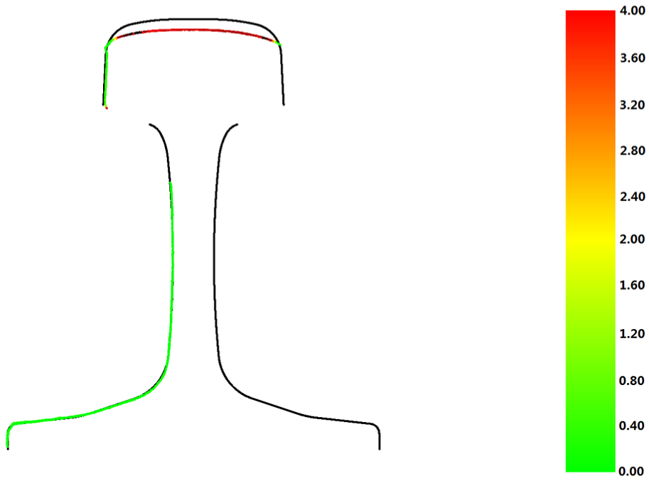
Color map of the wear amount on the cross-sectional plane.
Because the data are continuous on the 3D scale, the wear amount could be calculated on any cross section within the XY plane, and the Z coordinate describes its position along the rail. When the coordinate Z is 200 mm, lateral and vertical wear amounts on the cross section are demonstrated in Table 1. If the lateral or vertical wear amount is smaller than 5 mm, the result is qualified to the Chinese National Standard.
Wear amounts on the cross section with coordinate Z = 200 (unit: mm).

Validation of the method
To validate the proposed method, both the laser scanning and contact measurement results are compared with those from the structured light scanning in the laboratory. On the rail with the length of 500 mm, 10 cross sections are selected for the vertical wear measurements with the interval of 50 mm. On the cross section, the 2D profile of the nominal CAD model is imported as the reference, and then, the registration is implemented by the 2D singular value decomposition (SVD)-ICP algorithm.
The laser scanning system is constructed for the railway wear in the 2D scale as shown in Figure 14. The comparison results of vertical wear amounts between the structured light scanning and laser scanning are illustrated in Figure 15.

2D laser scanning system for the wear amount measurement.

Vertical wear amounts in comparison to laser scanning.
In Figure 15, it demonstrates that these vertical wear values have the same tendency at most of the cross sections. For the actual inspection, it only needs one-time measurement for structured light to scan the rail profile with 500 mm length rather than 10 times for laser scanning to acquire these 10 cross sections, although laser scanning is more effective in high-speed inspection with large measurement intervals. In the meanwhile, the wear amounts are larger in laser scanning because this method tends to introduce the deviation of the frame to the rail, while such deviation could be reduced in the point cloud registration in 3D scale.
The contact measurement of the rail wear in 2D scale is shown in Figure 16. For another section of the rail, the comparison results of vertical wear amounts between the structured light scanning and contact measurement are illustrated in Figure 17.

Contact measurement of the rail wear.

Vertical wear amount comparison to contact measurement.
In Figure 17, the same tendency for the vertical wear values from the two types of measurements at each cross sections is also presented. The vertical wear values are smaller in the contact measurement because the calibration of the measurement instrument is by reference rail without wear rather than by a digital model which might introduce some additional deviations. At the same time, it can be found that the structured light scanning has the same precision grade for wear amount characterization. For the 500-mm-long rail, one-time structured light scanning also outperforms the 10 times contact measurements on the inspection effectiveness aspect.
Conclusion
In this article, a structured light rail wear inspection system is developed and corresponding data processing methods are proposed for rail wear evaluation. With the point clouds from structured light wear inspection system on the railway, the data alignment is implemented by coarse registration and fine registration. For the alignment of the scanning data and nominal CAD model, random points sampling from CAD models is conducted to generate enough points for the registration, and the normal vectors of these points are calculated. In the coarse registration, the conformal geometric algebra method is utilized, and the motor is estimated by information of points on different surfaces of the rail. In the fine registration, the ICP algorithm is employed to achieve accurate alignment. With the online inspection results, the rail wear is visualized in the 3D scale by aligning the point cloud acquired and that from CAD model, and the vertical and lateral wear amounts are obtained on the cross section by slicing the aligned 3D point clouds. The 3D scale rail wear inspection method is verified by comparing vertical wear amounts with those from both 2D laser scanning and contact measurement on 10 cross sections. In future work, the low-speed wear inspection with the designed trolley on the railway turnout will be performed, which could complement the data gap of high-speed laser inspection with structured light scanning on some railway section with irregular profiles.
Footnotes
Handling Editor: AHI Mourad
Declaration of conflicting interests
The author(s) declared no potential conflicts of interest with respect to the research, authorship, and/or publication of this article.
Funding
The author(s) disclosed receipt of the following financial support for the research, authorship, and/or publication of this article: The work is supported by National Natural Science Foundation of China (Grant No. 51305370), the Fundamental Research Funds for the Central Universities (Grant No. 2682017CX036) and the Science and Technology Program of Sichuan Province (Grant No. 2018HH0144).