
Abstract
The reliable and repeatable experimental ground testing of aircraft actuator is an essential phase before flight testing. It is not an easy task to simulate the alternating aerodynamic forces on actuators reasonably and accurately in a laboratory. In this article, an experimental test bench is designed to simulate the aerodynamic forces by a hydraulic actuator, which replicates the operating conditions that the actuator will encounter in service. In order to improve the force control performance, a feed-forward compensator and a fuzzy proportional–integral–derivative controller are designed. Both simulation and experimental results show that the designed method can improve the control performance.
Keywords
Introduction
Actuation system is a vital link in the flight control system (FCS), providing motive force to actuate flight control surfaces. Therefore, performance of the actuator can have a significant influence on overall aircraft performance. 1
In Wang et al., 2 a speed controller for electric load simulator (ELS) was proposed to improve the dynamic performance and stability of ELS. In Wang et al., 3 in order to suppress actuator’s motion disturbance, a nonlinear robust dual-loop control scheme is developed. The presented test bench is designed to simulate the aerodynamic forces on the actuator, testing the dynamic and static performance, impedance characteristics, fault switchover, fault handling logic, and so on. However, high-accuracy force control is not an easy task, particularly when the tested actuator is in motion. Owing to the large oil modulus and high stiffness connection between the test bench and the actuator system, the force generated by hydraulic cylinder may drastically change even under slight motion disturbance, which could be harmful to the tested actuator. Although plenty of methods such as proportional–integral–derivative (PID) controller and proportional–integral (PI) controller with feed-forward compensator are proposed to solve this problem, most of them do not work well in engineering. Therefore, in this article, a feed-forward compensator and a fuzzy PID controller are designed to improve the force control performance.
The rest of this article is organized as follows. The description and work principle of the test bench are described in section “Description of the test bench.” The mathematical model of the test bench is built in section “Mathematical model of the test bench.” In section “Design and analysis of test bench controller,” a feed-forward compensator and a fuzzy PID controller are designed to improve the force loading precision. Experimental and simulation results validate the effectiveness of the designed method in section “Experimental results.”
Description of the test bench
The prototype of experimental test bench was built by AVTRON. The test bench consists of two servo systems in general: actuator system and loading system. 4 The presented test bench is as shown in Figure 1. The actuator system is a position servo system and the loading system is a force servo system which is a hydraulic actuator controlled by a servo valve. The shaft of the actuator system is connected to the loading system through the elastic element and the inertia load. It is desired that the force generated by the loading system can keep stable when the tested actuator is in motion so that the performance of the position controller for actuator can be precisely evaluated.

Scheme of the test bench.
Mathematical model of the test bench
Model of the hydraulic loading system
Several assumptions are made as follows:
The valve is an ideal four-way slide valve;
The spool of the valve radial-clearance leakage is negligible;
The supply source is stable and the return pressure is zero.
The linearization flow equation of valve is 5

where
Assume that the load pressure

where

with

where

where

where

Model of the hydraulic actuator system
The components of the hydraulic actuator system are same as the loading system, which means, the mathematical model is also the same as that of the loading system. For example,

where

Model of the servo valve
The electrohydraulic servo-valve dynamic state is approximately shown as follows 7

where
Model of the servo amplifier
The model of servo amplifier is described as below

where
Design and analysis of test bench controller
Many methods have been proposed to restrain the extra force c due to the motion disturbance of the actuator system.8–11 However, most of them cannot obtain satisfied performance in engineering. In this section, the feed-forward compensator and fuzzy PID controller are designed to improve the force loading precision. Based on the scheme of test bench and mathematical model of each component built in section “Mathematical model of the test bench,” the transfer function of the test bench with feed-forward compensator can be obtained, as shown in Figure 2. For a clean and brief expression, M(s) and G(s) are proposed. E(s) is the designed feed-forward compensator. In Figure 2


Transfer function of the test bench.
According to Figure 2, in order to build the model of the test bench in MATLAB/Simulink, the mathematical formula of compensator should be built. Assume that the control system is a linear system, and


In order to compensate the extra force caused by the motion of the actuator system, the equation is built as below

The second and higher orders in G(s) and C1(s) can be neglected in practice. Based on equations (10)–(12), it is obtained that

Then, the compensator is obtained as follows
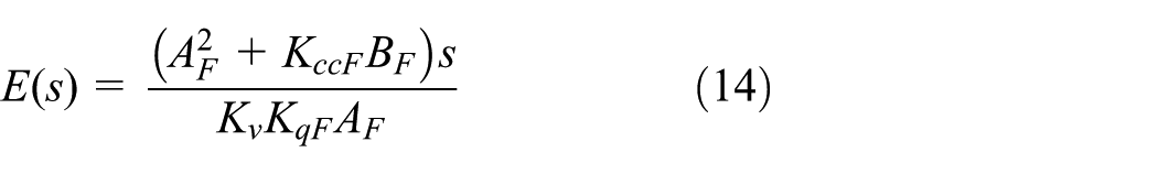
Therefore, the model of test bench with feed-forward compensator and fuzzy PI controller can be built in MATLAB/Simulink, as shown in Figure 3. The position loop is the actuator system. The force loop is the loading system which is applied to simulate the dynamic force disturbance. The fuzzy PID and compensator are applied to restrain the extra force caused by the motion of the actuator. The force reference of the loading system is given as 20 kN, and the given position reference signal of the actuator system is 2 mm sine wave with various frequencies. The simulation results are shown in Figure 4.

The model of test bench built in MATLAB/Simulink.
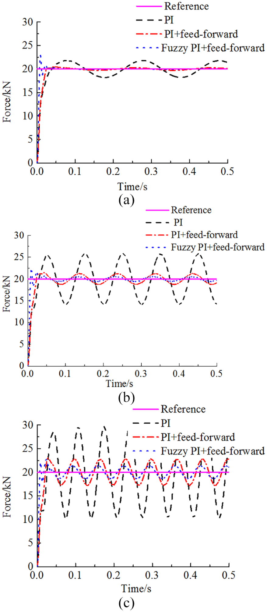
Simulation results of designed method: (a) simulation result of Case 1—5 Hz; (b) simulation result of Case 2—10 Hz; and (c) simulation result of Case 3—15 Hz.
It can be seen from Figure 4 that the settling time of designed method is shortest among those three methods and the overshoot is also the smallest, indicating the control precision against disturbance is enhanced significantly based on the designed method. Notice that with the increase in the motion frequency of the actuator system, the tracking performance gradually becomes poor, the reason of which is that the intensity of the disturbance is also connected with the motion frequency of the actuator system.
Experimental results
Four kinds of actuators can be tested on this bench, including elevator, rudder, aileron, and spoiler. In the automatic control mode, the bench generates the reference itself and works at position closed-loop or force closed-loop to test the performance of the actuator. In the host control mode, the bench receives arbitrary force or position reference to complete the test. The photo of the test bench is shown as Figure 5.

Photo of the test bench.
Time response experiment of the actuator system
The dynamic performance of the actuator system can be obtained by analyzing the rise time, the settling time, and the overshoot by time response experiment. The curves are shown in Figure 6, the actuator reference is ±10 mm step and the load reference is a 10-kN constant force. It can be seen that there is a small amount of overshoot in the stepping response and no obvious static error. Also, the force feedback stays constant, indicating the validity of the designed controller.

Curves of time response experiment.
Frequency response experiment of the actuator system
System bandwidth is an important performance index of the actuator system. The whole actuator system can be regarded as a filter, and the control accuracy will be higher with wider bandwidth. It reflects the response speed of the loading system. The phase delay and amplitude attenuation of the actuator system are analyzed offline by loading the data record of the host computer. Frequency response curves are shown in Figure 7, the load is 10 kN thrust, and the displacement reference of actuator is 2 mm, 2 Hz sine wave. It can be seen that the loading error is within ±0.4 kN, compared with simulation in Figure 4(a), the error is a bit larger, but still acceptable for engineering. In conclusion, the disturbance from the actuator system has been effectively restrained by the designed feed-forward plus fuzzy PI controller.
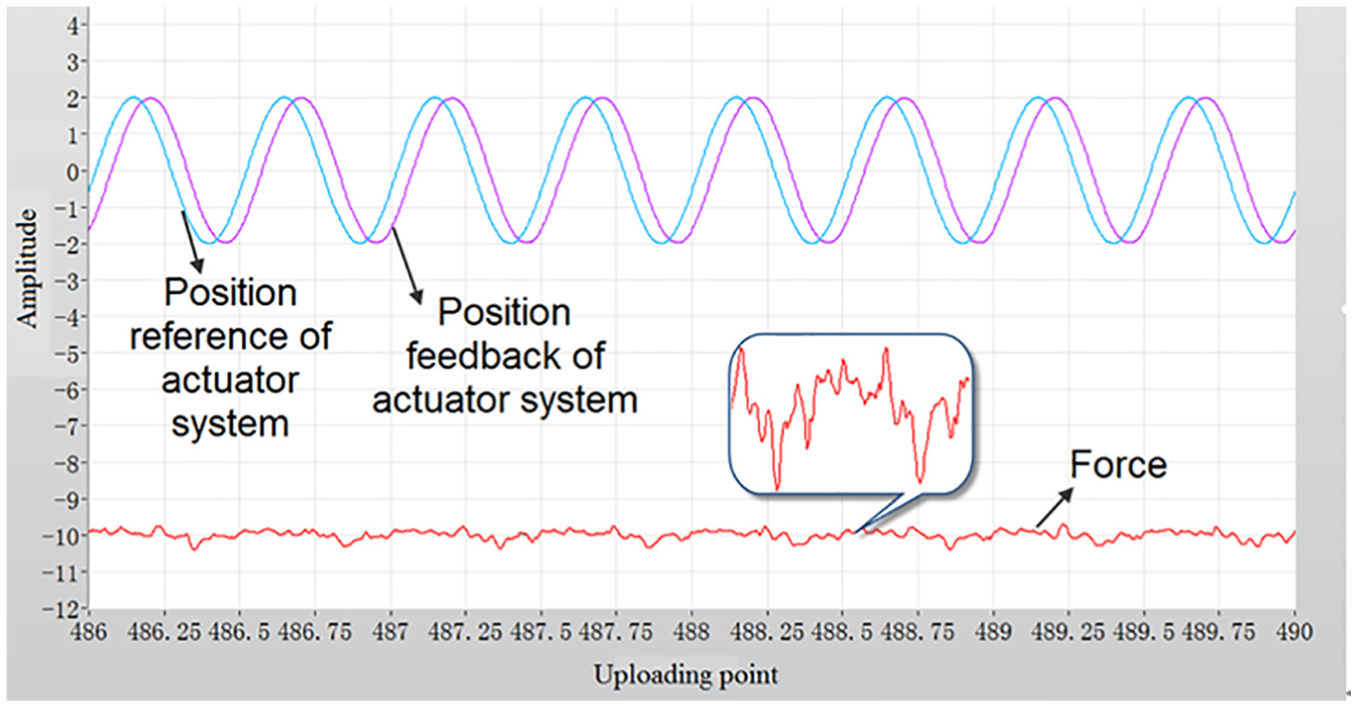
Curves of frequency response experiment.
Conclusion
The actuator system is an important part of the FCS, whose reliability is related to the reliability of the aircraft directly. In this article, the presented test bench simulates the aerodynamic forces and evaluates the actuator system with dynamical position disturbance. The method of feed-forward compensator and fuzzy PID controller is designed, which can restrain the position disturbance effectively. Simulation and experimental results demonstrate that the performance of the designed method is good, which meets the requirements of engineering.
Footnotes
Handling Editor: Shengfeng Qin
Declaration of conflicting interests
The author(s) declared no potential conflicts of interest with respect to the research, authorship, and/or publication of this article.
Funding
The author(s) disclosed receipt of the following financial support for the research, authorship, and/or publication of this article: This work was supported by the Basic Research Foundation of Northwestern Polytechnical University (NWPU) under Grant No. 3102016ZY002.