
Abstract
The characteristic of the spray within combustion chamber is one of the determining factors that affect the performance and exhaust gas emissions of an aero-engine. Recently, the holography technique has been successfully applied to spray atomization measurement due to its significant advances. In this article, an atmospheric test rig of pressure-swirl nozzle is built. The kerosene spray generated at the atmospheric condition and in an aero-engine combustor is measured. The Sauter mean diameter of the spray droplets is obtained. In addition, the theoretical analysis of film formation and sheet breakup processes are conducted. Comparison of theoretical analysis and experimental results on the spray atomization of a pressure-swirl nozzle is presented.
Introduction
Pressure-swirl nozzles are widely used in fuel systems of aero-engine due to their excellent atomization characteristics and simple geometry. The quality of liquid fuel atomization highly affects the formation of pollutants, combustion stability, and engine performance especially at high altitudes and low flight speed conditions.
During the last decades, spray characteristics and performance of pressure-swirl nozzles have been extensively investigated. AH Lefebvre and colleagues1,2 discussed the application of pressure-swirl nozzles in gas turbine combustion chambers, including the design procedures, theoretical analysis, and performance prediction. SM Jeng et al. 3 collaboratively investigated the fuel atomization process formed by a swirl cup using a phase Doppler particle analyzer (PDPA) system. Y Yingwen et al. 4 analyzed the effects of fuel mass flow rate, air temperature, and flux on spray feature in an annular combustor using particle image velocimetry (PIV). W Xiao and Y Huang 5 evaluated the lean blowout limits of liquid fuel with different swirl cups. C Liu et al. 6 investigated the relationship between spray pattern and combustion stability of a swirl cup combustor using planar laser-induced fluorescence (PLIF) and computational fluid dynamics (CFD). FZ Batarseh et al. 7 studied the aerodynamic instability of the atomizer spray based on high-speed video system and proper orthogonal decomposition (POD) method.
More recent studies have concentrated on fuel droplet particle cloud analysis based on laser diagnostics which is able to achieve more accurate information due to substantial progress in computer image processing. Laser holography is one of the most powerful instrumentations to provide accurate and detailed data on droplet size and distribution throughout the spray. Y Anezaki et al. 8 developed an automatic and accurate analysis device for laser holography method and researched the collective behavior of the droplets formed by the fan spray. J Muller et al. 9 used the digital holography to analyze spray-forming process and demonstrated its suitability for detection of fast particles. V Palero et al. 10 applied the digital in-line holography and digital image plane holography for the study of the droplets generated by a micro-dispensing device. The accuracy of measurement with both techniques was given and reasonable agreement was demonstrated. DR Guildenbecher et al. 11 investigated the droplet impact on a thin film and measured the temporal evolution of droplet number, size distribution, and velocity components with digital in-line holography. Experimental results were quantitatively in good agreement with high-speed shadowgraph results. Y Yang and BS Kang 12 analyzed the limitations and potential advantages of digital holography and successfully measured the velocity and size features in spray field. Uncertain analysis was given and comparison with common optical diagnostics showed that the measurement accuracy was satisfactory. The spray characteristics of fuel nozzles are difficult to predict because of coexistence of continuous and disperse phases. A Belhadef et al. 13 applied Eulerian model to simulate the pressure-swirl atomization. The mean velocity profiles of droplets show good accordance with the measurements by phase Doppler anemometry. C Qin and E Loth 14 employed the discrete random walk (DRW) model and reproduced the evolution of velocity fluctuations of droplets in the downstream of the pressure-swirl nozzles.
In order to provide insight into the spray atomization induced by a pressure-swirl nozzle, a test rig has been built and laser holography is used to investigate the main feature of the spray droplets. The fuel nozzle derives from a realistic aero-engine. The measurements are conducted not only under the atmospheric condition but also in a realistic working condition.The measurement is helpful for us to provide boundary conditions for combustion simulation and theoretical analysis of the combustion chamber in the future. In addition, theoretical analysis of the pressure-swirl nozzle spray is conducted to promote the understanding of the spray features.
Experimental setup
Atmospheric test rig
An atmospheric test rig is first designed and set up to study the fuel nozzle spray under unconfined atmospheric conditions. Figure 1 shows the line schematic diagram of the test rig for the laser holography. The pressure-swirl nozzle is tested using aviation kerosene to measure the pressure drop, the discharge coefficient, the spray angle, and spray pattern characteristics under varying injection pressures.

Schematic diagram of the spray test rig.
Compressed nitrogen is used to deliver fuel to the spray nozzle from the fuel tank. The supply nitrogen to the fuel tank is filtered and controlled by a pressure regulator. The injection pressure is monitored using a pressure transducer installed immediately upstream of the fuel nozzle. The fuel injection pressures utilized in this work are in a range of pressure differentials encountered at different stages of an aero-engine working cycle. To refill the fuel tank, both ball valves located between the tanks are to be closed, and the release valve on the fuel tank is to be open.
The aviation kerosene used for aircraft engine is chosen as the test liquid. During the experimental process, the kerosene is filtered to eliminate the undesirable solid particles and measured by a mass flow meter. The flow meter is calibrated against the direct method of flow measurement by collecting fuel in a volumetric vessel during a known interval of time. The fuel nozzle is mounted downward on a vertical plane, so that the kerosene spray is injected directly into a still air environment at ambient conditions. A container is utilized to collect and recirculate the injected fuel.
Considering the safety of operating, several release and ball valves are used. A pneumatic valve is installed immediately upstream of the nozzle to achieve the remote operation. The fuel properties measured at the injection condition are listed in Table 1. The kerosene density used here is 780 kg/m3 and the dynamic viscosity 2.0 × 10⁻³ Pa·s. The surface tension is 0.02432 N/m, and the injection pressure lies between 1 and 10 bars. Table 2 shows the configuration parameters of the pressure-swirl injector.
Kerosene properties.

Configuration parameters of the pressure-swirl injector.

Single sector test rig
The single sector test rig using electric resistance heating system of Northwestern Polytechnical University (NWPU) is utilized to perform spray measurement in the surrounding aero-engine combustor (Figure 2). The total pressure in the air tank is up to 60 bar and the incoming air can be heated up to 1000 K for 1.0 kg/s air using six electric resistance heaters of 750 kW. Since the pressure in the combustor varies with the engine power setting, the pressure regulating system is needed in the downstream of the combustor. The high-temperature gas is divided into two parts after leaving the combustor and exhausted into the atmosphere separately. A high-temperature sleeve valve in the main passage is used in conjunction with the orifice plate mounted on the bypass duct to adjust the pressure in the test section.
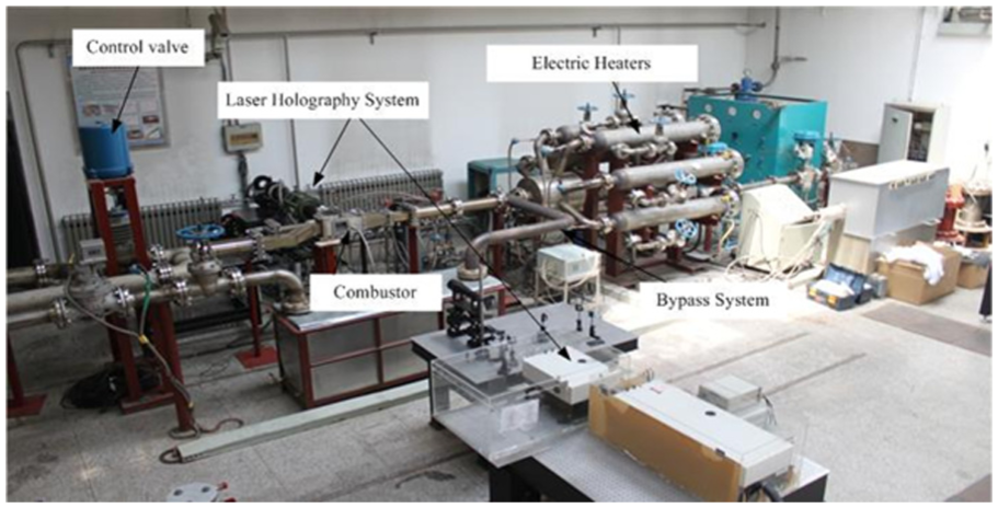
Single sector test rig.
The combustor model used in this work is based on a realistic aero-engine combustor shown in Figure 3. It has one rectangular window on each lateral side for optical measurements, which provides a 100 mm × 83 mm viewing area. The inner surfaces of quartz glass in the window are flushed with the combustor model. An igniter and fuel nozzle are installed on the upper air casing. Cooling nitrogen enters the window along the inner surface of the quartz glass from the front end to form an insulating film.

Aero-engine combustor.
Fuel nozzle specifications
The fuel nozzle investigated in this article is a simplex pressure-swirl nozzle. Due to the relatively simple geometry, it can be used in aero-engine combustion chamber or ground experimental facility.
Figure 4 shows the pressure-swirl nozzle used in this work and its internal geometry. The ratio of the maximum flow output to minimum flow is limited to 5:1. It would produce a kerosene hollow cone with wide spray angle but small penetration depth. In this fuel nozzle, the two tangential ports with square cross-section are 0.56 mm × 0.56 mm. The distance between the conical convergent part and the orifice is 1 mm and the diameter of the swirl chamber is 3 mm. Its exit orifice diameter is 2 mm. The liquid fuel is fed into the fuel nozzle through tangential passages giving the fuel a high angular velocity. The fuel is accelerated in the swirl chamber and forms a hollow cone with an air core vortex through a convergent sector. The discharging of the fuel through the orifice makes the fuel to become a thin sheet from which ligaments and finally droplets are shattered. These resulting droplets will be distributed through the primary zone in an expected pattern.

Photograph and schematic diagram of a pressure-swirl nozzle.
Data acquisition
Since the laser holography method can record the three-dimensional field information, it can measure the shape of each droplet in the entire spray and the collective spatial distribution with one recording. 5 After the data post-processing, it is capable of obtaining the droplet size and position distribution in the whole spray field. In terms of holography, there are two methods: inline method and off-axis method. In this study, the off-axis method is used to measure the diameter of the spray droplets although it needs a relatively long analysis time.
During the experiment, the laser beam is first split into two parts. One beam is routed to divert around the spray and the other is routed to illuminate the fuel spray. Then, these two beams are routed to interfere with each other on the holographic plate. By varying the difference of the optical path of object beam and reference beam to fit the laser coherence range, it is possible to record the interference fringes on the holographic plate. These interference fringes contain optical information with regard to the spray droplets. To analyze the high-speed spray droplets, a pulse Nd:YAG laser is employed and an instantaneous, instead of time-averaged, image is captured within the overall detecting volume. In the reconstructing mode, the spray image is reproduced in the space based on the interference fringes recorded on the plate. Using a charge-coupled device (CCD) camera, an enlarged photograph of the reconstructed image is taken and the diameter of each droplet is measured. The three-dimensional structure of the spray is obtained from the positional information of the droplets according to the focal point of the CCD camera. Details and demonstration of the laser holography technique can be found elsewhere. 15 The focus of the current work is on the experimental result analysis of the current pressure-swirl injector and comparison with the theoretical prediction.
In order to provide the insight of the droplet spatial distribution, different measurement positions were chosen across the spray as shown in Figure 5. The hatched region represents the fuel nozzle. Due to the axisymmetric feature of the pressure-swirl nozzle, the origin of the coordinates is placed at the center of the fuel nozzle orifice. The axis of the fuel nozzle is along the x-axis. The droplet information is evaluated within the domain of 1.4-mm thickness. The injection pressure investigated in this work is less than 14 bar according to its working conditions. The mass flow rate versus the injection pressure is shown in Figure 6. As expected, the mass flow rate increases gradually as the injection pressure rises in the operating range.

Measurement position using laser holography.

Plot of the mass flow rate.
Results and discussion
Results using laser holography
To clearly visualize the macroscopic spray transition from the orifice to fully developed spray, three holograms of the pressure-swirl nozzle spray under typical injection pressures are shown in Figure 7. The injection pressure is set to be 4, 9, and 10 bar and the fuel temperature is the ambient temperature of 300 K. The surrounding air pressure and temperature remain at atmospheric conditions.

Holograms of the pressure-swirl nozzle spray: (a) ΔP = 4 bar, (b) ΔP = 9 bar, and (c) ΔP = 10 bar.
There are several interacted but different processes of the spray from the orifice exit: film formation, sheet breakup, ligament breakup, and secondary atomization. The development process of disturbance wave on the spray cone surface is clearly different at three injection pressures. As the injection pressure increases, the position of ligament breaking up moves upstream rapidly.
Kerosene immediately spreads as a high-velocity conical sheet after it leaves the orifice. A hollow cone with a smooth surface and a certain angle is formed due to the swirl motion in the swirl chamber. However, after a short distance, the annular surface disturbance wave emerges, propagates downstream, and grows rapidly. Thus, the kerosene sheet starts to become thinner and unstable while the magnitude of the disturbance wave oscillation increases on the fuel cone surface. Then, the sheet fluctuates and forms many wrinkles, further breaking up into many ligaments. At the downstream, kerosene ligaments disintegrate into droplets. From Figure 7(a)–(c), the surface wave frequency increases and fuel sheet breakup occurs closer to the orifice. Figure 7(c) indicates that atomization occurs instantaneously after it leaves the fuel nozzle orifice due to a high injection pressure, which is called a prompt atomization mode. On the contrary, the successive stages of film formation, ligament shattering, and droplet breakup are clearly seen in Figure 7(a), which belong to classical atomization.
The distance between the orifice exit and the position where the initial ligament forms is usually defined as the breakup length. In the current work, liquid ligament starts to appear only several millimeters downstream of the orifice. Through precise measurement of Figure 7, it can be concluded that the break up length is about 15 mm at 4 bar injection pressure and decreases to 10 mm as the injection pressure rises to 10 bar. The spray cone angle, as another important performance parameter, is obtained from simple image post-processing. Although the injection pressure varies, the spray cone angle remains at 100° and almost uninfluenced.
The results of the laser holography essentially include the spray droplet size distribution in the overall measurement volume. Here, the size of the droplets generated at 9 bar is analyzed. Figure 8 shows the relative number of droplet distribution at two various axial positions. The two samples have been taken at 15 and 40 mm downstream from the pressure-swirl nozzle orifice, respectively. The droplet size distribution is very weakly related to the positions. The maximum relative number of droplets is less than 0.012 at x = 15 mm. The relative number of droplets larger than 100 µm is smaller than 0.002. The highest relative droplet number is about 0.01 with the corresponding diameter bounded between 60 and 80 µm. The corresponding relative droplet number is above 0.004 for droplet diameter of 30–100 µm. The size distribution at 40 mm position is quite similar to the distribution of first position, but slight difference exists. The maximum relative droplet number slightly decreases along the axial direction of the fuel nozzle. This indicates that large fuel droplets further disintegrate into smaller ones along the flow direction. The minimum droplet diameter which the current laser holography can discriminate is 7 µm in this experiment. The uncertainties of laser holography measurements of droplet diameter are estimated to be within 10%, and the uncertainties of droplet position are estimated to be within 3%.

Relative number of droplet distribution bar chart: (a) x = 15 mm and (b) x = 40 mm.
Sauter mean diameter (SMD) is an average droplet diameter which represents the liquid volume to surface area ratio corresponding to all the droplets. The SMD at the different positions along the axial direction is obtained, and the results are shown in Figure 9(a). The SMD in the entire measurement volume is 74µ m. There is a local maximum droplet diameter of 126.4 µm at 11 mm distance from the nozzle orifice. This distance agrees favorably with the breakup length shown in Figure 7. At downstream, the liquid ligaments break up into large droplets abruptly, where SMD reaches its maximum value. As for further downstream, the SMD distribution does not vary substantially anymore and in a zigzag shape. It can be concluded that 11 mm is the location where liquid film breaks up and ligament forms.

SMD of droplet distribution along the axial direction: (a) at atmospheric condition and (b) in aero-engine combustor.
The SMD of droplet distribution along the axial direction in an aero-engine combustor circumstance is shown in Figure 9(b). The incoming air stream is 5.5 bar and 860 K, which simulates the realistic aero-engine combustor incoming conditions. The SMD in the entire measurement distance is between 12 and 25 µm, which are much smaller than the value in the atmospheric conditions. This is because the relative motion between the surface of the fuel cone and the ambient air enhances the atomization process substantially. In the axial range of 5–15 mm, there are three positions corresponding to the large SMD. This phenomenon can be explained that the transverse disturbance waves cause rings of fuel to break away from the fuel sheet and this process is intermittent along the fuel sheet. At further downstream, the SMD decreases due to the disintegration of large droplets.
The droplet diameter distribution along the radial direction at two positions in an aero-engine combustor circumstance is shown in Figure 10. The magnitude of SMD at the two positions is 15.4 and 14.8 µm, respectively. Although the SMD only decreases slightly along the axial direction, the shape factor of the distribution is substantially different. It is revealed that the spectrum of droplet spread becomes narrower across a greater distance. This would be helpful for reductions in exhaust smoke, carbon monoxide, and good pattern factor. The uniformity of droplet diameter distribution may even mitigate the fluctuation in chemical reacting. 16

Droplet diameter distribution along the radial direction in aero-engine combustor: (a) x = 20 mm and (b) x = 30 mm.
Comparison with theoretical analysis
The linearized instability sheet atomization (LISA) model proposed by Schmidt is used to analyze the total spray behaviors caused by the pressure-swirl fuel nozzle primary breakup. Two main processes including film formation and sheet breakup are analyzed, respectively. According to the mass balance, the total velocity issued from the orifice can be defined by the injection pressure

here,

where the parameter
A thin conical sheet forms at the orifice and its thickness is determined by the mass flow rate

The mass flow rate here is set according to the measurement results, and thus, the liquid sheet thickness, h, will be evaluated. However, the pressure-swirl atomizer is commonly used in conjunction with swirl cup in aero-engine combustors. The air streams issued from the swirl cup impinge the fuel cone and considerably promote the atomization. This technique is a variation of the conventional pressure-swirl atomizer and often called air blast atomization. In this case, the sheet formation mechanism will be different. The SMD is only related with the wave number and independent of the fuel film thickness.
In the LISA model, 17 the most unstable disturbance wave growth rate is determined by the following equation
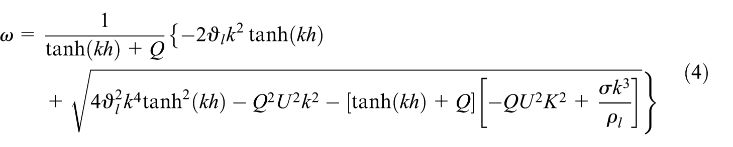
where Q is the density ratio of the ambient air and fuel; the parameters
The ligament length can be evaluated by Dombrowski and Hooper’s empirical equation 18
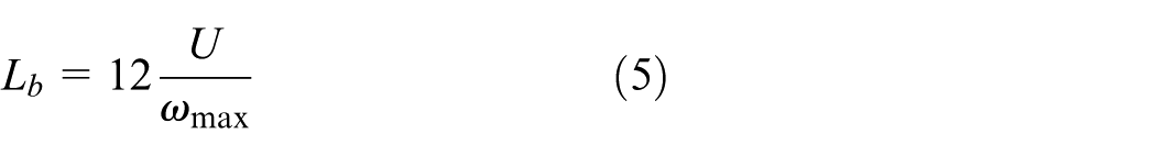
In equation (5), the constant 12 is recommended by Dombrowski and Hooper. And some researchers suggested that this parameter should be determined experimentally for each fuel nozzle. 19
Thus, the thickness of ligament will be calculated from the ligament length, thickness of the liquid film, and its radial position as follows

In equation (6), the parameter r is the average radial distance from the orifice center to the liquid sheet and can be determined by the diameter of the fuel nozzle orifice and the liquid sheet thickness. And this equation agrees favorably with the measurements up to Weber number 200. The diameter of the ligaments depends on the disturbance wave length or Weber number and is calculated as follows
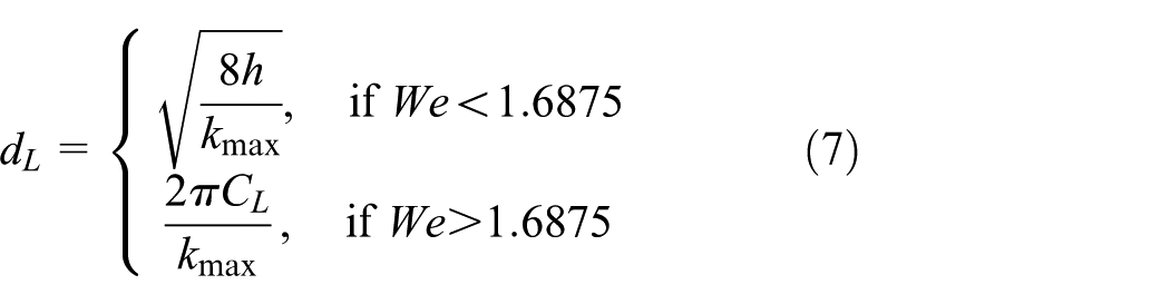
In equation (7), the parameter “We” denotes the Weber number. If the Weber numbers are low, the classical atomization mechanism is dominant and the former equation applies. And if the Weber numbers are high, the prompt atomization mechanism is dominant and the latter equation applies. For the operating condition in aero-engine combustors, it is always the short waves that cause the fuel sheet to shatter ligaments. The accompanying ligament diameter will be calculated by the latter equation. Then, the final SMD of spray droplets is then determined 20 as follows

here, Oh is the Ohnesorge number, which accounts for the influence of fuel viscosity on droplet breakup.
The theoretical analysis is conducted in atmospheric condition and aero-engine combustor under the injection pressure from 4 to 14 bar. Figure 11 shows the droplet velocity and Weber number of the pressure-swirl nozzle under various injection pressures. These two parameters are independent with the ambient operating conditions and only dependent on the injection pressure. As the injection pressure increases, the resulting droplet velocity and Weber number increase. At all the injector pressures, the calculated sheet thickness is 0.142 mm and the discharge coefficient is 0.577 because both the parameters are only functions of the physical dimensions. The calculated Weber number ranges from 4 to12, which shows that the mechanism of sheet disintegration mostly belongs to the short-wave disintegration.
(a) Droplet velocity and (b) Weber number of the fuel nozzle.
Figure 12 gives the ligament diameter, breakup length, breakup time, and Oh number of this pressure-swirl nozzle under different injection pressures. The ambient condition, whether it is in atmospheric condition or in an aero-engine combustor, has significant effects on the spray features. All the four parameters decrease as the injection pressure increases because the relative velocity between the fuel film and the surrounding air rises. The breakup length is less than 10 mm under 9 bar injection pressure in atmospheric condition, which is close to the result in Figures 7 and 9(a). When the pressure-swirl nozzle works in the aero-engine combustor, each parameter in Figure 12 drops dramatically due to the impingement of the atomization air stream on the fuel film cone. However, the injection pressure has less effect on the change trend.

Spray characteristics of the fuel nozzle: (a) ligament diameter, (b) breakup length, (c) breakup time, and (d) Oh number.
The SMD distributions in two working conditions are shown in Figure 13. The SMD is 78 µm at 9 bar in atmospheric condition, which is very close to the experimental result of 74 µm. The SMD is 19 µm at 9 bar in aero-engine combustor, which is a little bit larger than the measurement value of 16.14 µm. This validates the capability of the above theoretical analysis method.

SMD of the fuel nozzle spray.
Conclusion
The fuel atomization behavior in a pressure-swirl nozzle spray is studied experimentally and theoretically in the current work. The main conclusions can be summarized as follows:
The structure of a kerosene spray generated by a pressure-swirl nozzle is analyzed by means of a laser holography system. The acquired experimental results provide insight to the characteristics of fuel atomization. It demonstrates the suitability of the laser holography for aero-engine fuel nozzle spray measurement. The surface disturbance wave development process can be clearly observed from laser holography images. Breakup length is only a few millimeters and decreases as the injection pressure increases.
Theoretical analysis of a fuel nozzle spray is conducted in atmospheric conditions and aero-engine combustor circumstances. The parameters associated with atomization process, including the ligament diameter, breakup length, and breakup time, are obtained. And comparison of SMD with the measurement shows reasonable accordance.
Footnotes
Appendix 1
Handling Editor: Takahiro Tsukahara
Declaration of conflicting interests
The author(s) declared no potential conflicts of interest with respect to the research, authorship, and/or publication of this article.
Funding
The author(s) disclosed receipt of the following financial support for the research, authorship, and/or publication of this article: This work has been funded by the National Natural Science Foundation of China under grant no. 51576164.