
Abstract
In order to predict the atomization characteristics of the atomization process of zirconia dry granulation accurately, the influence of nozzle outlet diameter on the atomization characteristics of the atomization process of zirconia dry granulation is analyzed. The VOF method and RNG k-ε turbulence model are applied to numerically analyze the flow field of pressure-swirl nozzles with different outlet diameters of the atomization process of zirconia dry granulation, and the effects of outlet diameters on the spray cone angle, liquid film thickness, pressure distribution and velocity distribution are analyzed. The result shows that when the outlet diameter is increased from 3 to 4 mm, the diameter of air core and the outlet velocity of atomized liquid are increased, the spray cone angle is increased from 30.5° to 59.7° while the liquid film thickness is decreased, but when the outlet diameter is increased to 5 mm, the diameter of air core and the outlet velocity of atomized liquid are decreased, the spray cone angle is decreased to 27.6°, while the thickness of liquid film is decreased. The spray cone angle, moisture content of zirconia particles corresponding to nozzles with different outlet diameters are measured by the design of atomization experiment platform and the microstructure of zirconia particles are observed, which verifies the correctness of numerical analysis. Taking the atomization performance of nozzle into consideration, the pressure-swirl nozzle with the outlet diameter of 4 mm is better suitable for the atomization process of zirconia dry granulation.
Introduction
It is well known that zirconia dry granulation has many advantages over traditional zirconia wet granulation, such as simple process, energy and water saving and high cost-effectiveness.1–4 Atomization is an important part of zirconia dry granulation process, the atomization process is that the atomized droplets sprayed from the nozzle combine with the evenly mixed powder, the size of atomized droplets affect the percentage of powder in the zirconia particles prepared by dry granulation. Pressure-swirl nozzle is one of the key components of the atomization process of zirconia dry granulation, its outlet diameter has significant influence on the atomization characteristics of the atomization process of zirconia dry granulation.5–7 It is of great significance to analyze the influence of nozzle outlet diameter on the spray cone angle, liquid film thickness, pressure distribution and velocity distribution, so as to better predict the atomization characteristics of the atomization process of zirconia dry granulation.
Pressure-swirl nozzles, regardless of their simplicity, small atomization energy consumption and excellent performance, have a complex internal structure. The flow in the nozzle is two-phase flow, the distribution of internal flow field is complex, so it is difficult to carry out experimental observation and measurement. With the development of modern computer fluid mechanics, numerical analysis is one of the effective methods to study the nozzle flow field.8–13 Belhadef et al. 14 established the Euler model with high weber number and Reynolds number to simulate and experimentally study the atomization process of the pressure swirl nozzle, solving the average density balance equation of the liquid-gas interface and obtaining the Sauter average diameter of the droplets. Ibrahim and Jog 15 used the volume-of-fluid method to study the gas-liquid two-phase flow in the atomizer, made a nonlinear analysis of the instability of the liquid surface at the atomizer’s outlet and obtained that the length of the liquid film breaking would be shortened at a higher pressure. Boroujerdi and Kebriaa 16 developed an axisymmetric laminar turbulent two-phase flow solver and simulated the gas-water two-phase flow in a pressure-swirl atomizer, the result showed that laminar flow can predict the flow characteristics better than turbulent flow in a swirl pressure atomizer. On the basis of theoretical analysis, Using the method of fluid volume and numerical simulation. Birjandi et al. 17 analyzed the formation process of transient axisymmetric droplets of viscoelastic fluid entering the air from nozzles, it was found that increasing the fluidity coefficient, Wiessenberg number and viscosity ratio can reduce the limit length of droplets and the volume of primary droplets. Tao et al. 18 established a three-dimensional numerical model of the nozzle to simulate the cavitation flow of the internal nozzle, the result showed that under the given injection pressure, cavitation occurred with the decrease of back pressure. Although the above research objects are not the flow field of zirconia dry granulation atomization nozzle, but they are all based on CFD method to carry out numerical analysis of relevant nozzles, which lays a foundation for the flow field research of zirconia dry granulation atomization nozzle in this paper.
Combining with the research foundation of the flow field of related nozzles, the three-dimensional geometric models of nozzles with different outlet diameters are established, the simulation areas of nozzles with different outlet diameters are simplified, the three-dimensional physical model of nozzles with different outlet diameters are divided by hybrid meshes, the VOF method and RNG k-ε turbulence model are applied to analyze the interaction of air-atomized liquid two-phase flow in nozzles with different outlet diameters, and the correctness of numerical analysis is verified by setting up an atomization experimental platform. This method and conclusion can provide a theoretical reference for the analysis of the flow field in zirconia dry granulation atomization nozzle.
Nozzle geometry model
The pressure-swirl nozzles are easy to manufacture even in small sizes, provide good atomization quality and have low clogging tendency.19–21 Figure 1 shows that the pressure-swirl nozzle consists of tangential entry ports, swirl chamber (straight section and contraction section) and outlet straight section. The liquid atomization process of pressure-swirl nozzle can be briefly illustrated in Figure 2. Under the action of pressure, the atomized liquid is injected from the pressure-swirl nozzle into the tangential entry port and has certain tangential velocity, the swirl motion is formed in the swirl chamber, the atomized liquid moves downward from the upper part of the nozzle in the spiral trajectory. Because of the existence of spiral motion, the atomized liquid in swirl chamber is subjected to certain centrifugal force, then the low-pressure area is formed near the nozzle outlet and an air core is formed near the nozzle axis, the atomized liquid extends to the nozzle outlet in the form of rapid spiral motion, forming a ring liquid film. When the atomized liquid with axial and radial velocity leaves the nozzle, it presents the hollow conical liquid film due to the tension of centrifugal force, then breaks into small droplets under the combined action of aerodynamic force and wave growth.22–24

Sketch of pressure-swirl nozzle structure.

Atomization mechanism of pressure-swirl nozzle.
The structural parameters of different nozzles with different outlet diameters are shown in Table 1, Ds is the diameter of swirl chamber; d0 is the diameter of outlet; Ls is the length of straight section of swirl chamber; L0 is the length of straight section of nozzle outlet; L is the total length of nozzle; dt is the diameter of tangential inlet; θ is the contraction angle, refers to the total angle of the cone.
Structural parameters of different nozzles.

Calculation method
In order to solve the flow field distribution of atomized liquid in nozzle, the atomized liquid at the tangential inlet of the nozzle is taken as the numerical solution object. The flow pattern of the atomized liquid in the nozzle is incompressible gas-liquid two-phase turbulent flow. To facilitate the analysis and solution, the following assumptions are made:
The atomized liquid is incompressible Newtonian fluid.
There is no chemical reaction and physical phase transition between the air and atomized liquid in nozzle.
The influence of friction heat between the atomized liquid and nozzle wall must be ignored and there is no energy dissipation.
With the standard wall function, there is no slip on the wall of passageway and the effect of reflux is not considered.
The evolution is assumed to be isothermal.
VOF method
It is the key for numerical simulation to capture the interface of gas-liquid two-phase flow in nozzle. At present, there are four main numerical methods for capturing gas-liquid interface: VOF (Volume-of-Fluid) method, ALE (Arbitrary-Lagrangian-Eulerian) method, gradient method, full Lagrangian method.25–27 The VOF method was first proposed by Hirt and Nichols, 28 this method is easy to reconstruct the interface without changing the mesh. Further, it can accurately track the geometrical and topological changes of the gas-liquid interface, which is suitable for calculating any two non-mixing, non-permeable and negligible slip between two phases. The working substances of this study are atomized liquid and air (when compressibility is not strong), which is suitable for VOF method. In this method, the volume fraction ψ of a scalar field function is defined to represent the volume fraction of the second fluid in the mesh computing area of nozzle. If ψ = 0, the first fluid is all in the mesh computing area of nozzle, if 0 < ψ < 1, one part of the mesh computing area of the nozzle is the first fluid and the other part is the second fluid, if ψ = 1, the second fluid is all in the mesh computing area of the nozzle. In this paper, the air is the first fluid and the atomizing liquid is the second fluid.
Given the time and the initial volume fraction distribution of atomizing liquid filling nozzle, the transport equation of volume fraction function Q is as follows:

In the gas-liquid mixing area of the nozzle, the expressions of fluid density ρ and dynamic viscosity μ are as follows:


In the formula, ρ is the fluid density, ψ is the volume fraction of the atomized liquid, μ is the dynamic viscosity, u is the fluid velocity, x, y, z is the space rectangular coordinate symbol, t is the time of atomizing liquid filling nozzle, 1 is the air, 2 is the atomized liquid.
Control equations
The atomized liquid moves downward in high-speed spiral motion in nozzle, the flow state is incompressible turbulent flow. According to the analysis of actual flow field, the control equations of gas-liquid two-phase flow in nozzle include continuity equation, momentum equation and energy equation. In order to simplify the numerical analysis, there is no heat transfer in nozzle and no friction heat loss between and within phases is considered, the energy equation can be neglected. The control equations are as follows:
Continuity equation:

Momentum equation:
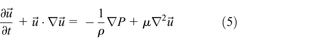
In the formula, P is the time-averaged pressure, ρ is the fluid density, μ is the dynamic viscosity, u is the fluid velocity, x, y, z is the space rectangular coordinate symbol, t is the time of atomizing liquid filling nozzle, 1 is the air, 2 is the atomized liquid.
Equation discretization
Based on the above equations, ANSYS Fluent is used to analyze the flow state of atomized liquid in nozzle. The VOF model and RNG k-ε turbulence model are selected to solve the flow field, the implicit unsteady solver is selected as solver. The pressure interpolation method is PRESTO variance and the pressure-velocity coupling method is SIMPLE method. In order to obtain higher accuracy, the volume fraction equation and momentum equation are discretized by the second-order upwind formula, the convergence residuals of all variables are less than 10-4, the relaxation factor is set as the sub-relaxation factor. The time step length is 10−5 s, and the iteration time is 300 times at most. The condition of convergence is that the outlet flow rate of atomizing liquid is equal to the inlet flow rate, which shows that the outlet flow rate is no longer changed, and the gas-liquid mixing interface tends to be stable.
Physical model
Boundary condition
Because the boundary conditions of three nozzles with different outlet diameters are the same, only 2#nozzle is selected as the research object in this paper. The boundary conditions are set as shown in Figure 3. In the numerical calculation, the atomized liquid with the density of 2000 kg/m3 and the viscosity of 0.7 kg/(mãs) is selected as the working material. The surface tension coefficient of the atomized liquid is about 0.048 N/m. The boundary conditions are as follows:
Inlet boundary condition: the nozzle inlet is set as velocity inlet, the velocity is 1.17m/s, and the volume fraction of atomized liquid is set to 1, which means that only the atomized liquid enters nozzle, and the volume fraction of atomized liquid in nozzle is 0 when the flow field is initialized.
Outlet boundary condition: the outlet boundary condition is set as pressure outlet, the gauge pressure is set as standard atmospheric pressure, and the volume fraction of atomized liquid is set as 0, which means that the atomized liquid will not return to the computational grid area to participate in numerical calculation after it flows out from nozzle outlet.
Wall boundary condition: it is set as non-slip and adiabatic wall.

Physical model of pressure-swirl nozzle.
Mesh generation
Figure 4 shows the 3D mesh division of pressure-swirl nozzle. Three kinds of pressure-swirl nozzles are modeled in 1:1 ratio, ANSYS ICEM is used to divide the tangential inlet section and the straight section of swirl chamber into unstructured meshes, and structural meshes are used to divide the structure below the straight section of swirl chamber. In order to improve the calculation accuracy, prism mesh is used to encrypt the area where the inlet and tangential hole intersect, the area where the inlet and swirl chamber intersect and the area near the wall surface, O-mesh is used to encrypt the nozzle inlet and outlet. Finally, the mesh quality is checked accordingly, the mesh quality is evaluated by skewness. Skewness is the difference between the actual node shape and the equal volume equilateral node, which is one of the most important mesh quality measures.1#nozzle has 120632 mesh units and 56391 nodes, the skewness is more than 0.4. There are 138304 mesh units and 71732 nodes in 2#nozzle, the skewness is more than 0.55. 3#nozzle has 150319 mesh units and 83250 nodes, the skewness is more than 0.3. The maximum mesh is set to 0.5 mm, which is convenient for capturing the phase interface accurately.

3D mesh generation of pressure-swirl nozzle: (a) 1#nozzle, (b) 2#nozzle, and (c) 3#nozzle.
Calculation results and analysis
The volume fraction distribution
The volume fraction distribution of atomized liquid in three nozzles is shown in Figure 5. It can be seen from Figure 5(a) when the atomized liquid is filled with 1#nozzle, the area with the volume fraction of 0.9-1.0 occupies 60% of total area, the area with the volume fraction of 0.1-09 occupies 15%, and the area with the volume fraction of 0.0-0.1 occupies 25%. Further, the volume fraction distribution of atomized liquid which fills 2#nozzle is shown in Figure 5(b), the area with the volume fraction of 0.9-1.0 accounts for 50% probably, the area with the volume fraction of 0.1-0.9 accounts for 22% probably, and the area with the volume fraction of 0.0-0.1 accounts for 28% probably. Additionally, Figure 5(c) describes the volume fraction distribution of atomized liquid filling 3#nozzles, the area with the volume fraction of 0.9-1.0 accounts for about 75% of total area, the area with the volume fraction of 0.1-0.9 accounts for about 15%, and the area with the volume fraction of 0.0-0.1 accounts for about 10%.
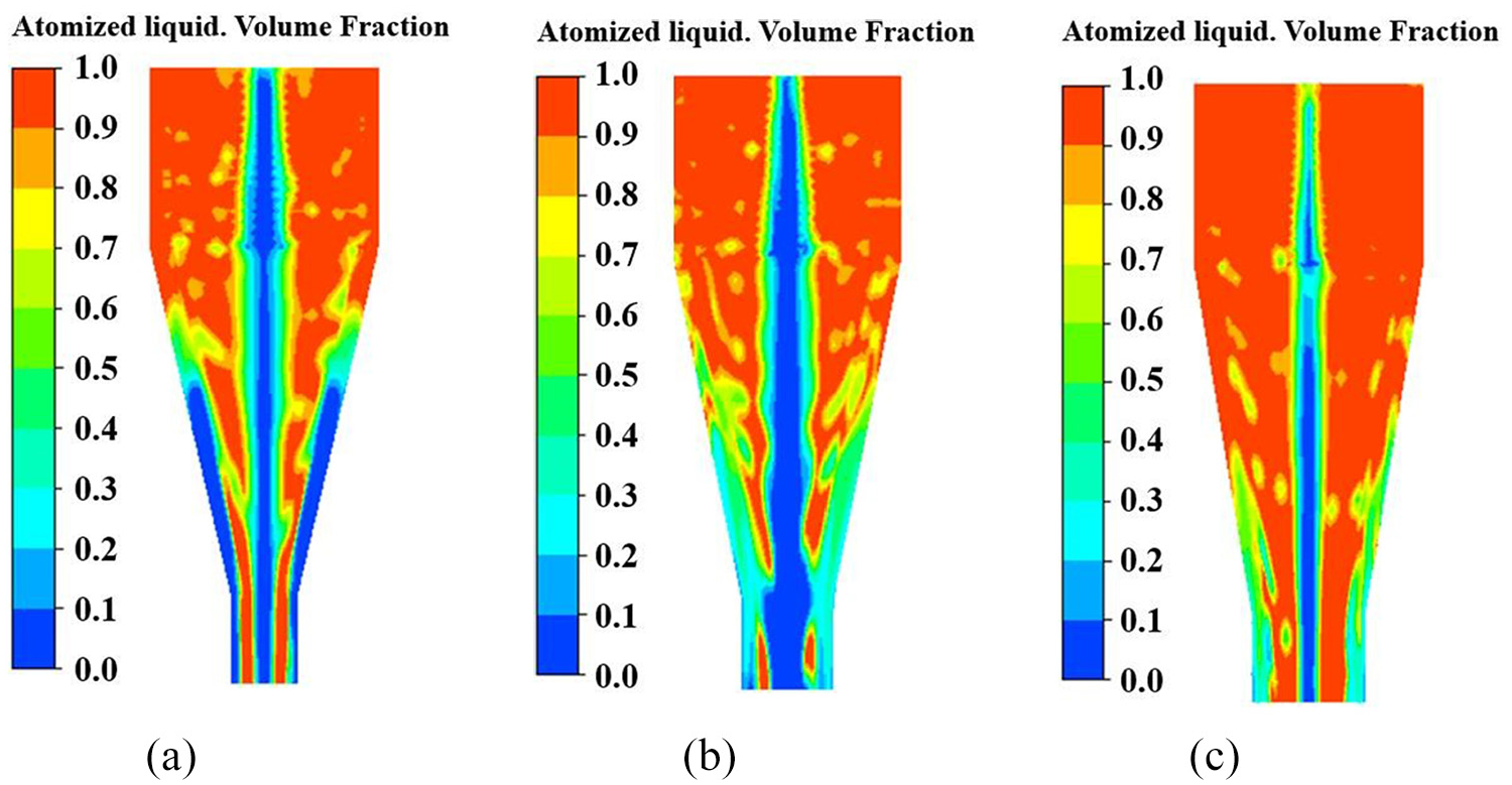
The volume fraction distribution of atomized liquid: (a) 1#nozzle, (b) 2#nozzle, and (c) 3#nozzle.
The area where the volume fraction of atomized liquid is 0.0-0.1 is air core area. The air core area of 1#nozzle is similar to 2#nozzle, but only half of air core area is distributed on the axis and the other half is posted on the wall surface of outlet section, the diameter of air core increases firstly then decreases, and tends to be stable along the axis finally. Further, the air core area of 2#nozzle is largest, which is distributed along the axis, the diameter of air core increases gradually along the axis in a cone shape. However, the air core area of 3#nozzle is smallest, which is distributed along the axis, the diameter of air core increases gradually along the axis and then remains unchanged.
When the atomized liquid fills 1#nozzle, part of air core area sticks to the wall of outlet section, which will reduce the flow coefficient of atomized liquid flowing along the wall, the diameter of air core which distributes along the axis is smaller, it makes that the spray cone angle will be smaller. Compared to 1#nozzle, the air core area of 2#nozzle is larger, so the diameter of air core at the outlet is larger, and the spray cone angle is larger. However, the air core area of 3#nozzle is smallest, it makes that the diameter of air core at the outlet is smallest, so the spray cone angle is smallest. Actually, the spray cone angle reflects the range of spray distribution, the larger the spray cone angle is, the stronger the shearing effect of atomized liquid is surrounded by the gas, so the atomized liquid is mixed with external gas more fully, which makes that the size of atomized liquid particles is smaller. Moreover, the liquid film thickness of atomized liquid is the area where the volume fraction of nozzle outlet is 0.9-1.0. By comparison, the liquid film thickness is: t2 < t1 < t3. The thinner the liquid film thickness is, the less surface tension of liquid film can maintain the shape of liquid film, it is easier to destabilize and break into liquid belt or liquid wire, the thinner the liquid film at the nozzle outlet is, the better for atomization.
Axial pressure distribution
The axial pressure distribution in three nozzles is shown in Figure 6. In the swirling flow field of nozzle, the pressure decreases in turn along the axis. the atomized liquid enters swirl chamber from four tangential entrances and flows downward at high speed. The smaller the radial distance is, the faster the swirling velocity is, which leads to gradual decrease in pressure. The axial pressure is relative pressure. As shown in Figure 6(a), the area with pressure value of 3.4 × 10⁴−4.0 × 10⁴ Pa accounts for 55% of total area, the area with pressure value of 1.0 × 10⁴−3.4 × 10⁴ Pa accounts for 45%. Further, Figure 6(b) shows that the area with pressure value of 3.4 × 10⁴-4.0 × 10⁴ Pa accounts for about 30%, the area with pressure value of 1.0 × 10⁴−3.4 × 10⁴ Pa accounts for about 70%. Besides, Figure 6(c) shows that about 40% area have pressure value of 3.4 × 10⁴-4.0 × 10⁴ Pa, about 60% area have pressure value of 3.1 × 10⁴−3.4 × 10⁴ Pa. The high-pressure area mainly distributes in the swirl chamber, and its pressure value is 3.4 × 10⁴−4.0 × 10⁴ Pa. On the contrary, the low-pressure area mainly distributes below the swirl chamber to nozzle outlet, and its pressure value is 1.0 × 10⁴−3.4 × 10⁴ Pa.

Axial pressure distribution: (a) 1#nozzle, (b) 2#nozzle, and (c) 3#nozzle.
The swirl chamber of 1#nozzle is full of high-pressure area, because the outlet diameter is too small, which results in the friction force of atomized liquid flowing downward too large, so the swirl chamber must have larger pressure to make atomized liquid flowing downward along the wall. Actually, the high-speed motion process can lead to a large amount of energy loss, the low-pressure area is mainly distributed below the swirl chamber, which forms low-pressure area in the central area of nozzle, due to the existence of pressure difference, the air from outside is sucked into the nozzle to form air core distributed along the axis, the air core area with axis distribution is about 12.5% of total area. Further, the high-pressure area of 2#nozzle mainly distributes on the both sides of swirl chamber, and the central area of swirl chamber mainly forms low-pressure area, which shows that the atomized liquid does not suffer too much friction when it flows at high speed from top to bottom along the wall due to the increase of outlet diameter, it does not cause too much energy loss, but the low-pressure area is distributed along the axis, extending from top to bottom, which can lead to greater pressure difference between the inside and outside of nozzle, so that more gas from outside is sucked into the inside of the nozzle to form air core that accounts for 28% of the total area along the axis. Moreover, the high-pressure area of 3#nozzle mainly distributes in swirl chamber, and a small part distributes below the swirl chamber, it shows that the further increase of outlet diameter can’t effectively reduce the distribution of high-pressure area in swirl chamber, which leads to the downward flow velocity of atomized liquid being too fast, the flow rate of atomized liquid is largest in 3#nozzle compared with the former two nozzles, so the driving pressure is largest, although this process can make the spray velocity of atomized liquid faster, but actually it can also cause excessive energy loss, the low-pressure area is all distributed below the swirl chamber, forming a pressure difference with outside pressure, so that the air from outside is sucked into the nozzle, and the air core that occupies 10% of total area along the axis is formed in nozzle. The low-pressure area in nozzle can cause pressure difference between the inside and outside of nozzle, the existence of pressure difference can cause the air from outside to be sucked into the inside of nozzle, which can affect the size of air core area.
Radial pressure distribution
In order to fully understand the influence of outlet diameter on pressure distribution, the radial pressure distribution of three nozzles is shown in Figure 7, taking Z = 5 mm section as example. The radial pressure is relative pressure. As can be seen in Figure 7(a), the area with the pressure value of 3.4 × 10⁴-4.0 × 10⁴ Pa accounts for about 60% of total area while the area with the pressure value of 3.0 × 10⁴-3.4 × 10⁴ Pa accounts for about 40% of total area. Figure 7(b) shows that the area with the pressure value of 3.4 × 10⁴-4.0 × 10⁴ Pa accounts for about 30% of total area while the area with the pressure value of 3.0 × 10⁴-3.4 × 10⁴ Pa accounts for about 70%. Figure 7(c) shows that the area with the pressure value of 3.4 × 10⁴-4.0 × 10⁴ Pa accounts for about 70% of total area while the area with the pressure value of 3.0 × 10⁴-3.4 × 10⁴ Pa accounts for about 30%.

Radial pressure distribution: (a) 1#nozzle, (b) 2#nozzle, and (c) 3#nozzle.
The high-pressure area is located at the edge of the circular area, while the low-pressure area is located at the center of circular area. The high-pressure area of 2#nozzle is smallest, but the low-pressure area in the circular center is largest, which shows that 2#nozzle does not need too much pressure to make atomized liquid overcome the friction with the wall and spray out from the nozzle outlet. The pressure difference between the nozzle and external environment is largest, which results in a large amount of air from outside being sucked into the nozzle, forming air core distributed along the axis, and the air core area is largest. Further, the high-pressure area of 1#nozzle is larger than 2#nozzle, but the low-pressure area of circular center is smaller than 2#nozzle. Due to the smaller outlet diameter, excessive pressure is needed in swirl chamber to make atomized liquid overcome friction with wall and spray smoothly from the outlet, which can cause the pressure difference between the internal and external environment of nozzle to be too small, the air core is formed along the axis, and its area is smaller. Additionally, the high-pressure area of 3#nozzle is largest, which indicates that the further increase of outlet diameter can cause the spray velocity of atomized liquid to be too fast, this process needs to consume more pressure as driving force, but the low-pressure area in the circular center is smallest, so the pressure difference between the internal and external environment of nozzle is smallest, which leads to the minimum air core area. The existence of the low-pressure area will produce pressure difference, which will affect the size of the air core area.
Axial velocity distribution
The axial pressure distribution of three nozzles is shown in Figure 8. It can be seen from Figure 8(a) when the atomized liquid is filled with 1#nozzle, the area with the velocity of 1.17-2.49 m/s accounts for about 70% of total area, which mainly distributes in swirl chamber and the upper half of contraction section, the area with the velocity of 2.49-6.45 m/s accounts for about 20% of total area, which mainly distributes in the lower half of contraction section and on both sides of outlet straight section, and the area with the velocity of 6.45-7.77 m/s accounts for about 10% of total area, which distributes in the center area of the axis of outlet straight section. Moreover, Figure 8(b) shows that when the atomized liquid fills 2#nozzle, the area with the velocity of 1.17-2.49 m/s accounts for 40% of total area, it mainly distributes on the both sides of swirl chamber and the upper half wall of contraction section, the area with the velocity of 2.49-6.45 m/s accounts for 35% and mainly distributes in contraction section, and the area with the velocity of 6.45-7.77 m/s accounts for 25% of total area, which mainly distributes in the central area of the axis and on the both sides of the wall of outlet straight section. Besides, Figure 8(c) shows that the area with the velocity of 1.17-2.49 m/s accounts for about 30%, which mainly distributes in the upper half of swirl chamber and the upper half of contraction section, the area that mainly distributes in contraction section with the velocity of 2.49-6.45 m/s accounts for about 50%, and the area with the velocity of 6.45-7.77 m/s accounts for about 20%, which mainly distributes in the axis central area of outlet straight section.
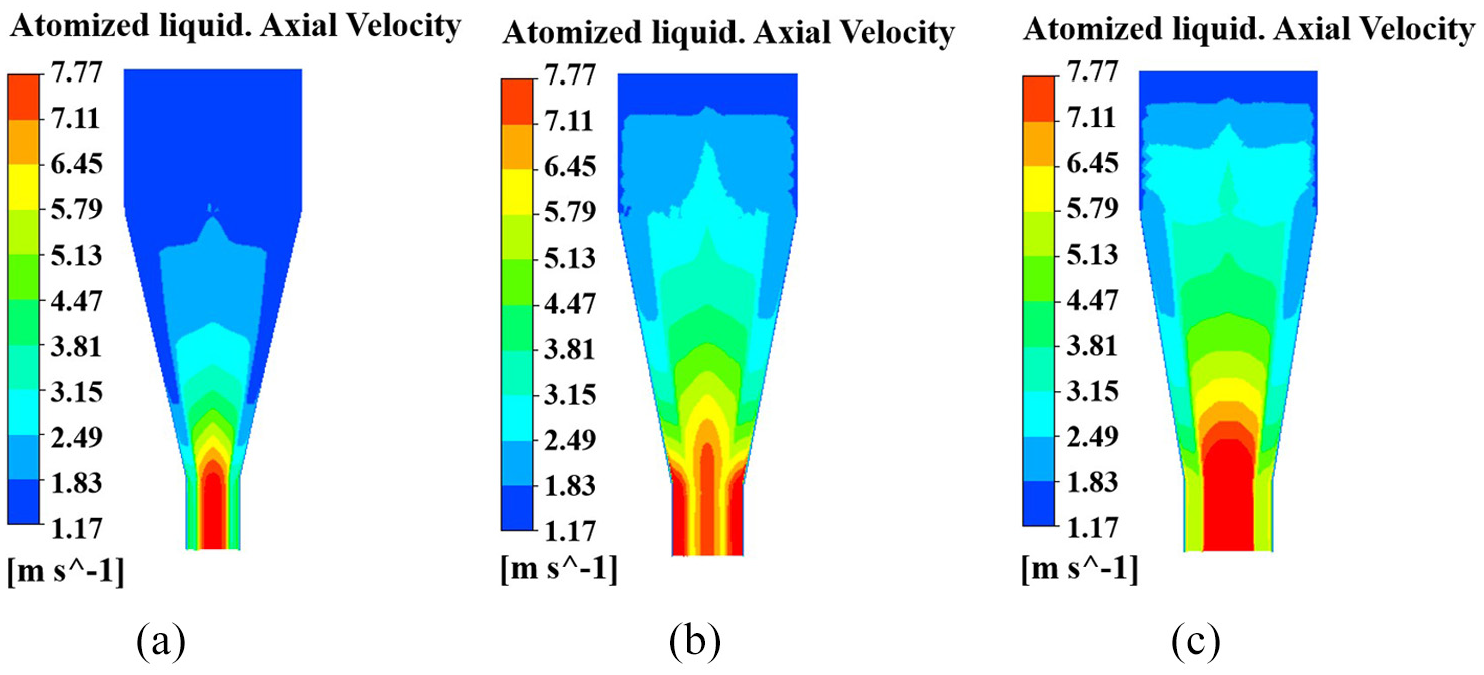
The axial velocity distribution of atomized liquid: (a) 1#nozzle, (b) 2#nozzle, and (c) 3#nozzle.
It is necessary to analyze the velocity field of three nozzles by combining the axial velocity vector distribution of atomized liquid that is shown in Figure 9. The maximum velocity area of atomized liquid in the swirl chamber and the contraction section of 1#nozzle is smallest, which is caused by the smaller outlet diameter and the larger friction force of atomized liquid flowing down the wall. Further, the axial velocity of atomized liquid in the swirl chamber and contraction section of 2#nozzle and 3#nozzle is larger than 1#nozzle, which indicates that the increase of outlet diameter can effectively reduce the friction force exerted by atomized liquid flowing along the wall, and the maximum velocity area of the swirl chamber and contraction section of 3#nozzle is largest.

The axial velocity vector distribution of atomized liquid: (a) 1#nozzle, (b) 2#nozzle, and (c) 3#nozzle.
The velocity of atomized liquid which flows along the wall to the outlet reaches the maximum value in the axis center of outlet straight section. Because the flow process must follow the conservation of mass flow, the thickness of liquid film will gradually become thinner on the both sides of outlet straight section. Further, the maximum velocity area of 1#nozzle and 3#nozzle is not distributed on the both sides of outlet straight section, while the maximum velocity area is distributed on the both sides of outlet straight section of 2#nozzle, which indicates that the spray velocity of 2#nozzle is highest, the atomized liquid is sprayed along the both sides of outlet straight section, while the velocity on the both sides of outlet straight section of 1#nozzle and 3#nozzle does not reach the maximum value. After flowing out from nozzle outlet, the liquid film has big velocity difference with the outside air, which will generate large aerodynamic force, it is conductive to atomization. The maximum velocity area distributed on the both sides of outlet straight section of nozzle can affect aerodynamic force, which can affect the effect of atomization.
Radial velocity distribution
The radial velocity distribution of atomized liquid in three nozzles is shown in Figure 10, taking Z = 26 mm section as example. As shown in Figure 10(a), the area with the atomized liquid velocity of 1.17-6.45 m/s accounts for about 70% of total area, while the area with the atomized liquid velocity of 6.45-7.77 m/s accounts for about 30% of total area. However, Figure 10(b) shows that the area with the atomized liquid velocity of 1.17-6.45 m/s accounts for about 35% of total area, while the area with the atomized liquid velocity of 6.45-7.77 m/s accounts for about 65%. Further, Figure 10(c) shows that the area with velocity of 1.17-6.45 m/s approximately accounts for 65% of total area, while the area with velocity of 6.45-7.77 m/s approximately accounts for 35%.

The radial velocity distribution of atomized liquid: (a) 1#nozzle, (b) 2#nozzle, and (c) 3#nozzle.
Combining with the radial velocity vector distribution of atomized liquid that is shown in Figure 11, the velocity field of atomized liquid in nozzle can be more comprehensively analyzed. Under the action of pressure, the atomized liquid enters the swirl chamber of nozzle from four tangential inlets and rotates in it. Further, the maximum velocity area of the swirl chamber of 1#nozzle and 3#nozzle are all distributed in the center of circle, while the maximum velocity area of the swirl chamber of 2#nozzle are mostly concentrated in the center of circle, and a small part is distributed in the edge of circle. It shows that the velocity of atomized liquid flowing along the wall at the outlet of 1#nozzle is smaller, because the outlet diameter is smaller, which will cause greater friction between the atomized liquid and the wall along the way, and the velocity of atomized liquid film flowing along the wall will be smaller. Compared with 1#nozzle, the outlet diameter of 3#nozzle is larger, the atomized liquid sprays along the axis of nozzle with faster speed, but the spray velocity along the wall does not reach the maximum. However, the velocity of the atomized liquid film flowing along the wall in the swirl chamber of 2#nozzle reaches the maximum, so the velocity of the atomized liquid spraying along the two sides of outlet straight section will also be the largest, which will generate greater aerodynamic force and the liquid film is easy to break up, which is conducive to achieving good atomization effect.

The radial velocity vector distribution of atomized liquid: (a) 1#nozzle, (b) 2#nozzle, and (c) 3#nozzle.
Experimental analysis
Experimental system
In order to verify the correctness of numerical calculation, an experimental platform which is built is shown in Figure 12, the atomized liquid with the density of 2000 kg/m3 and the viscosity of 0.7 kg/(mãs) is selected as the experimental material. First of all, it is necessary to open the switch of piston container, add enough atomized liquid to the piston container, then start the electromotor and generate the power source of experimental system. Further, the motor transmits the power to the belt drive mechanism, the rotation of shaft is accelerated by gear drive mechanism, it is set to optimum speed by reducer, which drives the crank to rotate, making slider and piston move forward. At last, the atomized liquid flows out from the piston extrusion mechanism and enters into nozzle from the tangential inlet of nozzle along the flow channel, which sprays out along the nozzle outlet and combines with homogeneous zirconia powder to complete the dry granulation process of zirconia. The inlet velocity of nozzle is controlled by a flow control valve, from the formula M = ρvA, A = πr2, v = M/ρA is obtained, among them, M is the mass flow, ρ is the density of atomized liquid, v is the inlet velocity of atomized liquid, A is the cross-sectional area of nozzle inlet pipeline, r is the tangential inlet radius of nozzle, the inlet velocity of atomized liquid is indirectly controlled by adjusting the flow rate by a flow control valve. Process I shows that the atomized droplets sprayed from three different pressure-swirl nozzles combine with uniform zirconia powder to complete the wetting process of zirconia powder. Process II shows that the high-performance digital camera is used to photograph the spray cone angle when the atomized liquid sprays out from nozzle outlet, using the image-Pro Plus post-processing software to calculate and measure the spray cone angle. Moreover, the main measuring instruments are moisture tester and scanning electron microscope, process III shows that the moisture content of zirconia particles is measured by a moisture tester, and process IV shows that the scanning electron microscope is used to observe the micromorphology of zirconia particles.

Schematic of the experimental setup.
Experimental results and analysis
Spray cone angle
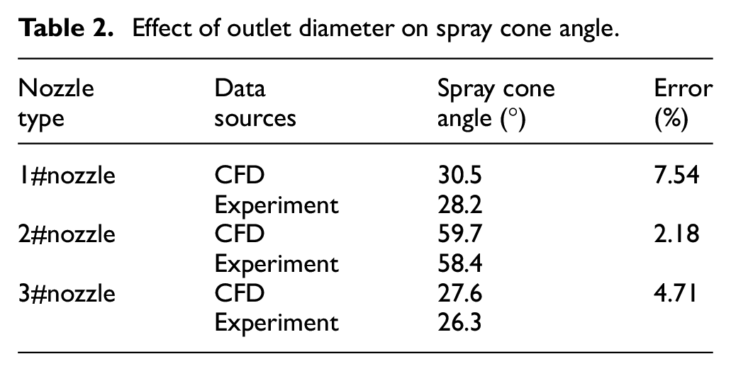
A high-performance digital camera is used to photograph the spray cone angle when the atomized liquid is sprayed from three nozzles with different outlet diameters, the spray cone angle of three nozzles with different outlet diameters obtained by experiment and numerical calculation is shown in Table 2. As can be seen from Table 2, with the increase of outlet diameter, the spray cone angle increases firstly and then decreases. With the increase of outlet diameter in certain range, the flow rate of atomized liquid in nozzle is increased, increasing the swirl intensity of gas-liquid two-phase flow in nozzle, which will increase spray velocity of atomized liquid and the spray cone angle at nozzle outlet. However, when the outlet diameter of nozzle is further increased, the discharge of atomized liquid at nozzle outlet is increased, which decreases the mixing time of gas-liquid two-phase flow in nozzle. Moreover, the swirl intensity of gas-liquid two-phase flow in nozzle is decreased, so that the spray cone angle does not increase but decrease. When the outlet diameter nozzle is less than 4 mm, the discharge of atomized liquid is limited and the gas-liquid two-phase mixing time is sufficient in nozzle, so the flow rate of atomized liquid in nozzle plays a leading role in the swirl intensity of gas-liquid two-phase flow in nozzle. When the outlet diameter of nozzle increases from 3 to 4 mm, the flow rate of atomized liquid in nozzle is increased continuously, which makes that the swirl intensity of gas-liquid two-phase flow in nozzle is increased, so the spray cone angle is increased from 28.2° to 58.4°. However, when the outlet diameter of nozzle is increased from 4 to 5 mm, the flow rate of atomized liquid in nozzle is further increased, which decreases the mixing time of gas-liquid two-phase flow and the swirl intensity of gas-liquid two-phase flow in nozzle, the spray cone angle is decreased from 58.4° to 26.3° consequently. It also can be seen from Table 2 that the spray cone angle of numerical analysis is slightly larger than experimental measurement, because the influence of wall friction on atomized liquid is neglected in numerical analysis, but with the increase of outlet diameter, the experimental results are basically consistent with the results of numerical analysis.
Effect of outlet diameter on spray cone angle.
Moisture content of zirconia particles
In order to further verify the correctness of numerical analysis, the homogeneous zirconia powder are atomized and humidified by spraying droplets from the outlets of three pressure-swirl nozzles with different outlet diameters, and then the atomized zirconia powder are granulated by dry granulation technology to prepare zirconia particles. The moisture content of zirconia particles is measured by a moisture tester, which can reflect the size of atomized droplets, so it can indirectly reflect the thickness of liquid film at the outlet of each nozzle. The moisture content of zirconia particles corresponding to three nozzles with different outlet diameters is shown in Figure 13, before 10 s, with the increase of measuring time, the moisture content of zirconia particles corresponding to three nozzles with different outlet diameters is increased gradually, but after 10 s, the moisture content of zirconia particles does not change. In the same test time, the moisture content of zirconia particles corresponding to 1#nozzle is largest while the moisture content of zirconia particles corresponding to 2#nozzle is smallest, and the moisture content of zirconia particles corresponding to 3#nozzle is slightly less than the moisture content of zirconia particles corresponding to 1#nozzle, so it can indirectly explain that the thickness of liquid film sprayed from three nozzles with different outlet diameters is t2 < t3 < t1, which can indirectly verify the correctness of numerical analysis.

Moisture content of zirconia particles.
Micromorphology of zirconia particles
The micromorphology of zirconia particles corresponding to three nozzles with different outlet diameters is observed by scanning electron microscopy, and the size of zirconia particles corresponding to each nozzle is measured. Further, the composition of zirconia particles includes atomized droplets and zirconia powder, the weight of three piles of zirconia powder is measure by electronic scale and make the weight of each pile of powder equal, since the zirconia powder is uniformly mixed and the content of zirconia powder in the corresponding zirconia particles of each nozzle is almost equal, so the size of zirconia particles can indirectly reflect the size of atomized droplets sprayed by each nozzle, which can reflect the thickness of liquid film at the outlet of each nozzle. The micromorphology of zirconia particles corresponding to three nozzles with different outlet diameters is shown in Figure 14. In general, the size of zirconia particles corresponding to three nozzles with different outlet diameters is compared, the size of zirconia particles corresponding to 2#nozzle is smallest, which shows that the size of atomized droplets sprayed from 2#nozzle outlet is smallest, so the liquid film thickness formed at 2#nozzle outlet is thinnest. However, the size of zirconia particles corresponding to 1#nozzle and 3#nozzle is larger than 2#nozzle, indicating that the size of atomized droplets sprayed from 1#nozzle and 3#nozzle outlet is larger than 2#nozzle, so the thickness of liquid film formed at the exit of 1#nozzle and 3# nozzle is larger than 2#nozzle. The micromorphology observation of zirconia particles corresponding to three nozzles with different outlet diameters can further prove the correctness of numerical analysis.

Micromorphology of zirconia particles: (a) 1#nozzle, (b) 2#nozzle, and (c) 3#nozzle.
Conclusions
The VOF method and RNG k-ε turbulence model are applied to numerically analyze the flow field of pressure-swirl nozzles with different outlet diameters of the atomization process of zirconia dry granulation, the effects of outlet diameters on the spray cone angle, liquid film thickness, pressure distribution and velocity distribution are analyzed, the experimental results are in good agreement with the results of numerical analysis, which can provide a theoretical guidance for the analysis of flow field in zirconia dry granulation atomization nozzle.
Compared with 1#nozzle and 3#nozzle, in the process of internal flow of atomized liquid in 2#nozzle, the pressure consumption is smallest in swirl chamber of nozzle, and the pressure difference between inside and outside of nozzle is largest, making that the largest diameter of air core formed inside the nozzle, which leads to the largest angle of atomized liquid sprayed from the nozzle outlet. Moreover, the liquid film thickness formed in the straight section at the nozzle outlet is smallest, and the velocity of the nozzle outlet is largest. So 2#nozzle has the best atomization performance by comparative analysis.
When the zirconia particles are prepared by dry granulation, taking the atomization performance of nozzle into consideration, the pressure-swirl nozzle with the diameter of 4 mm should be selected.
Footnotes
Handling editor: James Baldwin
Declaration of conflicting interests
The author(s) declared no potential conflicts of interest with respect to the research, authorship, and/or publication of this article.
Funding
The author(s) disclosed receipt of the following financial support for the research, authorship, and/or publication of this article: This work is supported by the National Natural Science Foundation of China (Grant No. 51964022).